Download to read offline
![Pratik M. Bhombe et al. Int. Journal of Engineering Research and Applications www.ijera.com
ISSN : 2248-9622, Vol. 5, Issue 4, ( Part -1) April 2015, pp.13-19
www.ijera.com 13 | P a g e
Grayscale Image Transmission over Rayleigh Fading Channel in
a MIMO System Using Different Digital Modulation Techniques
with STBC
Animish S. Andraskar1
, Pratik M. Bhombe2
, Shantanu S. Bhusari 3
, Prof. Shital
N. Raut4
1
(Department of Electronics & Telecommunication Engineering, Vishwakarma Institute of Technology,
Pune-411037)
2
(Department of Electronics Engineering, Vishwakarma Institute of Technology, Pune-411037)
3
(Department of Electronics Engineering, Vishwakarma Institute of Technology, Pune-411037)
4
(Department of Electronics Engineering, Vishwakarma Institute of Technology, Pune-411037)
ABSTRACT
The consistent demand for higher data rates and ability to send large volumes of data without compromising the
quality of communication has led the development of a new generations of wireless systems. But range and data
rate limitations are there in wireless devices. In an effort to overcome these limitations, Multi Input Multi Output
(MIMO) systems can be used which also increase diversity and improve the bit error rate (BER) performance of
wireless systems. They also increase the channel capacity, increase the transmitted data rate through spatial
multiplexing, and/or reduce interference from other users. MIMO systems thus make a promising
communication systems because of their high transmission rates without additional bandwidth or transmit power
and robustness against multipath fading. This paper focuses on transmission of an image file using 2x2 MIMO
system that achieves a full diversity gain using Alamouti’s Space Time Block Coding technique for 2
transmitting antennas and 2 receiving antennas. Different modulation techniques viz. BPSK, QPSK, 16-QAM
and 64-QAM are used and performances has been evaluated in terms of BER vs. SNR to find out the best
modulation technique in a given environment. Space-Time Codes have been used which in addition to the time
and spectral domain, also exploit the spatial domain. Simple maximum likelihood decoding algorithm is used at
the receiver side to decode the received encoded signal.
Keywords- BER, PSK, QAM, Rayleigh fading, Maximum Liklihood Detection, MIMO, SNR, STBC.
I. INTRODUCTION
Maxwell predicted the existence of EM waves in
1867 and Marconi transmitted radio signals across
Atlantic ocean in 1901. Since then there has been
rapid advancements in the field of wireless
communication. The first generation mobile
communication systems were analog. The 2nd
generation (2G) used digital multiple access
technology. The 2G system (called GSM), along with
its add-ons (viz. HSCSD and GPRS) provided data
rates of 22.8 Kbps to 172.2 Kbps.[2] EDGE system
based on GSM, with two add-ons namely enhanced
circuit switched data (ECSD) and the enhanced
general packet radio service (EGPRS) became very
popular. The maximum data rate of the EDGE system
is 473.6 Kbps. The third generation (3G) provided
data transfer rates more than 2 Mbps.[8] Universal
Mobile Telephone System (UMTS) is a leading
technology for 3G systems. WCDMA is the air-
interface technology for UMTS. The next generation
is Internet Protocol (IP) based and called as fourth
generation (4G). LTE - advanced which is one of the
system standards for 4G is expected to achieve data
download rates of about 3 gigabits per second and
upload rates as high as 1.5 Gbps.[12] . With
evolution in mobile communication standards, the
demand for higher data rates has increased .
In a single carrier transmission (SISO) to achieve
higher data rates, larger bandwidth is required. But
the available spectrums are limited and hence
stringent constraints are imposed on its use. Thus it
is necessary to pack more number of bits per Hz of
bandwidth.
A MIMO (multiple-input multiple-output)
system has multiple antennas at both transmitter and
receiver sides. Each antenna element uses the same
time and frequency resources enabling capacity to be
increased without increase in bandwidth or increased
transmit power. MIMO systems provide a promising
solution for future wireless communications systems.
In MIMO systems the transmitter and the receiver
antennas communicate in such a way that the quality
(the bit error rate (BER) or the data rate) for each
user is improved.
RESEARCH ARTICLE OPEN ACCESS](https://image.slidesharecdn.com/c504011319-150414045252-conversion-gate01/75/Grayscale-Image-Transmission-over-Rayleigh-Fading-Channel-in-a-MIMO-System-Using-Different-Digital-Modulation-Techniques-with-STBC-1-2048.jpg)
![Pratik M. Bhombe et al. Int. Journal of Engineering Research and Applications www.ijera.com
ISSN : 2248-9622, Vol. 5, Issue 4, ( Part -1) April 2015, pp.13-19
www.ijera.com 14 | P a g e
The wireless communication systems also suffer
from multipath fading which gives rise to higher
noise and thus the high bit error rate. MIMO systems
resort to spatial diversity to combat fading. For this
purpose Space Time Block Coding (STBC) is
employed which exploits spatial domain along with
time domain. STBC creates redundancy and thus
reduces outage probability of the transmitted signal.
It is thus possible to achieve high reliability, high
spectral efficiency and high performance gain. The
goal of STBC is to find code matrices that satisfy
certain optimality criteria.
This paper is organized as: Section II providing
information on system model for MIMO; Section III
describing the algorithm and simulation model used
for image transmission; Section IV stating the results
obtained from simulation; and Section V giving the
conclusions drawn.
II. MIMO SYSTEM MODEL
The MIMO system consists of three main
elements, namely the transmitter, the receiver and the
channel. [2]
Let us consider a MIMO system having NT
transmitting antennas and NR receiving antennas as
shown in fig. 1.
Fig. 1 MIMO system representation
The MIMO system can be characterized as:
nxHy . (1)
where y and x are received and transmitted
vectors respectively and n is the noise vector. The
received signal is a linear combination of each
transmitted signal plus noise.
MIMO system is expressed in terms of its
channel. For a system with NT transmitting antennas
and NR receiving antennas, channel matrix is of size
NR x NT. Each element in this matrix is called as the
channel coefficient between one of the antennas from
both transmitter and receiver side. Channel
coefficient between antenna 1 to 1 is specified with
h11, from antenna 1 to 2 as h21, etc. In this way we
can obtain transmission matrix or channel matrix H
.The channel matrix H is denoted as:
(2)
Where each entry hi,j denotes the attenuation and
phase shift (transfer function) between the jth
transmitter and the ith
receiver. [3]
Advantages of MIMO system:
• Increased system capacity
• Better coverage
• Higher data rates
• Robustness against multipath fading
III. SIMULATION MODEL
The simulation model consists of following
blocks:
Fig. 2 Block diagram for grayscale image
communication using STBC and MIMO.
3.1) INPUT DATA
An array of binary data is generated by
converting intensity value of each pixel in the
grayscale image to be transmitted into its equivalent
binary values and is passed on to the next stage for
symbol mapping.](https://image.slidesharecdn.com/c504011319-150414045252-conversion-gate01/75/Grayscale-Image-Transmission-over-Rayleigh-Fading-Channel-in-a-MIMO-System-Using-Different-Digital-Modulation-Techniques-with-STBC-2-2048.jpg)
![Pratik M. Bhombe et al. Int. Journal of Engineering Research and Applications www.ijera.com
ISSN : 2248-9622, Vol. 5, Issue 4, ( Part -1) April 2015, pp.13-19
www.ijera.com 15 | P a g e
3.2) DIGITAL MODULATION TECHNIQUES
In binary phase shift keying (BPSK), the phase
of the carrier signal is varied according to the
modulating signal. It uses two phases to represent the
two binary digits '0' and '1'. BPSK is only able to
modulate 1 bit/symbol and hence is unsuitable for
high data-rate applications.
Quadrature phase shift keying (QPSK) uses
phase shifts separated by multiples of π/2. More
efficient use of bandwidth is achieved since each
signaling element represents two bits rather than one.
The input stream of binary digits is converted into
two separate bit streams of half the data rate by
taking alternate bits for the two streams. Each of
them is then modulated as BPSK and two modulated
signals are then added together and transmitted.
[6][7].
In quadrature amplitude modulation (QAM), the
data is transmitted by varying both amplitude and
phase of the carrier signal. Generally two carrier
waves are taken which are orthogonal (shifted by 90
degree) to each other. For QAM, each carrier is ASK
modulated at different phases, further the data can be
carried at different amplitudes.[5]
In 16-QAM, four bits are grouped by taking two
bits from each carrier to form a symbol. The number
of possible symbols is 24
=16 which are combination
of real and imaginary values[11]. In 64-QAM, each
symbol is represented by 6 bits. In higher order QAM
for the mean energy of the constellation to remain
same, the constellation points must be closer together
and are thus more susceptible to noise and other
corruption. By moving to a higher-order
constellation, it is possible to transmit more data but
less reliability.
3.4) MIMO ENCODER
Alamouti's STBC for 2x2 MIMO system is used
in the MIMO encoder. The encoder takes a block of
two modulated symbols s1 and s2 in each encoding
operation and gives it to the transmitting antennas
according to the code matrix,
Fig. 3 Transmission matrix
This can be interpreted as follows:
During the first symbol period (t), the first antenna
transmits s1 and the second antenna transmits s2.
During the second symbol period (t+T), the first
antenna transmits -s2* and the second antenna
transmits s1* being the complex conjugate of s1 [1]
[4].
Thus we are transmitting both in space (across
two antennas) and time (two transmission intervals).
Hence is called space-time coding.
If s1 and s2 are the information sequence from the
first antenna and the second antenna respectively.
Then
s1= [ s1, -s2*] (3)
s2= [ s2, s1*] (4)
Inner product of s1 and s2 is zero i.e., these sequences
are orthogonal.[2]
3.5) CHANNEL
The signal which is being transmitted through a
channel experiences a rapid fluctuation of the
amplitude, phase or multipath delay of a radio signal,
called as fading. Fading is caused by number of
signals arriving at the reception point through
different paths. We used Rayleigh fading which is a
statistical model for the effect of propagation
environment on radio signal to create such an
environment . It is viewed as a reasonable model for
tropospheric and ionospheric signal propagation as
well as for the effect of urban environment on radio
signal transmission. Rayleigh fading models assume
that the magnitude of a signal that has passed through
such a transmission medium (also called as
communications channel) will vary randomly, or
fade, according to a Rayleigh distribution — the
radial component of the sum of two uncorrelated
Gaussian random variables.[10]
Rayleigh fading channel model can be expressed as:
for r≥0 (5)
In the above Rayleigh pdf, r is the envelope
amplitude of the received signal, and 2σ2
is the pre-
detection mean power of the multipath signal.
MIMO system is described in terms of the
channel. For a 2x2 MIMO, the channel matrix will be
of size 2x2 consisting of four entries [3].
Assuming that h1(t) and h2(t), which are the
fading coefficients from antennas 1 and 2
respectively, at time t. are constant across two
consecutive symbol transmission periods i.e. h1(t) =
h1(t+T) then signals after passing through the
channel can be expressed as, [2]
r1 = h1s1 + h2s2 + n1 (6)
r2 = -h1s2* + h2s1* + n2 (7)
r1 and r2 are the signals received at the receiver side.
3.6) MIMO DECODER
The decoder system consists of a channel
estimator, a combiner and the maximum likelihood
decoder.[1] We have assumed that the channel
coefficients h1 and h2 can be recovered perfectly at](https://image.slidesharecdn.com/c504011319-150414045252-conversion-gate01/75/Grayscale-Image-Transmission-over-Rayleigh-Fading-Channel-in-a-MIMO-System-Using-Different-Digital-Modulation-Techniques-with-STBC-3-2048.jpg)
![Pratik M. Bhombe et al. Int. Journal of Engineering Research and Applications www.ijera.com
ISSN : 2248-9622, Vol. 5, Issue 4, ( Part -1) April 2015, pp.13-19
www.ijera.com 16 | P a g e
the receiver and used as the CSI. The combiner
combines the received signal as follows:
*
221
*
11
2
2
2
1
*
221
*
1
~
1 )( nhnhsrhrhs (8)
1
*
2
*
212
2
2
2
1
*
21
*
1
*
2
~
2 )( nhnhsrhrhs (9)
and sends them to the maximum likelihood detector.
[2]
Maximum Liklihood decoder is used to
decode the received symbols. The job is to make
‘best estimate’ of transmitted signal si(t) upon
receiving r(t). Depending on the modulation and
transmission strategy used, the receiver usually has
the knowledge about the signal constellation that is in
use . The fig. 4 shows a two-dimensional signal
space showing a signal vector si and a received vector
and the noise vector ω.
Fig. 4 Signal space showing signal vector si and r .
So, the decision rule simply is to choose the
signal point si among all valid ‘si-s’, if the received
vector 'r' is closest to si in terms of Euclidean
distance. The receiver then takes a decision that r = si.
The MLD minimizes the following decision metrix
over all possible values of s1 and s2.
|r1 - h1 s1 - h2 s2|2
+ |r2 + h1 s2* - h2 s1*|2
(10)
Equivalently, the decision rule for each combined
signal Sj˜, j = 1, 2 becomes: [2]
Pick Si iff
),(||)1(),(||)1(
~
222
2
2
1
~
222
2
2
1 kjkiji ssdsssds (11)
ki
Thus the ML decoder decision statistic decodes in
favor of s1 and s2 over all possible values of s1 and s2.
3.7) DIGITAL DEMODULATION
Demodulation is done with respective digital
demodulation technique of the symbols s1 and s2
which are obtained from MLD. The original bits are
obtained back in this way and the transmitted data file
is recovered from this data
3.8) ALGORITHM FOR TRANSMISSION OF A
GRAYSCALE IMAGE
1. Read the image file and find out the intensity
levels for all the pixels.
2. Convert these intensity levels into their
equivalent binary representations.
3. Modulate this binary data using PSK or QAM
digital modulation technique.
4. This signal is then encoded using Alamouti's
Space-Time Block Coding (STBC) scheme and
transmission matrix is generated.
5. Multiply the STBC encoded data with the
channel equation and send it to the receiver.
6. Decode the received data using maximum
likelihood decoder and demodulate it.
7. Convert the demodulated binary representations
into their equivalent intensity levels.
8. Rearrange the image pixels and save the new
image file.
IV. RESULTS
Fig. 5 shows the original image to be transmitted
using a 2x2 MIMO system using Alamouti's STBC.
PSK and QAM modulation techniques have been
used to modulate the data before encoding.
The performance of the system is analyzed using
BER (Bit Error Rate) which represents errors in a
given number of transmitted bits over a
communication channel caused due to the noise,
interference or distortion.[6] Bit error rate is plotted
as a function of SNR. BER vs. SNR performance is
plotted for received image file with each of the
modulation techniques.
Fig. 5 Original Image](https://image.slidesharecdn.com/c504011319-150414045252-conversion-gate01/75/Grayscale-Image-Transmission-over-Rayleigh-Fading-Channel-in-a-MIMO-System-Using-Different-Digital-Modulation-Techniques-with-STBC-4-2048.jpg)
![Pratik M. Bhombe et al. Int. Journal of Engineering Research and Applications www.ijera.com
ISSN : 2248-9622, Vol. 5, Issue 4, ( Part -1) April 2015, pp.13-19
www.ijera.com 18 | P a g e
The plot in Fig.10 shows BER vs. SNR
performance of the image received with diversity and
without diversity for each of the four modulation
techniques used.
Out of the four modulation techniques (BPSK,
QPSK, 16 QAM, 64 QAM), best results
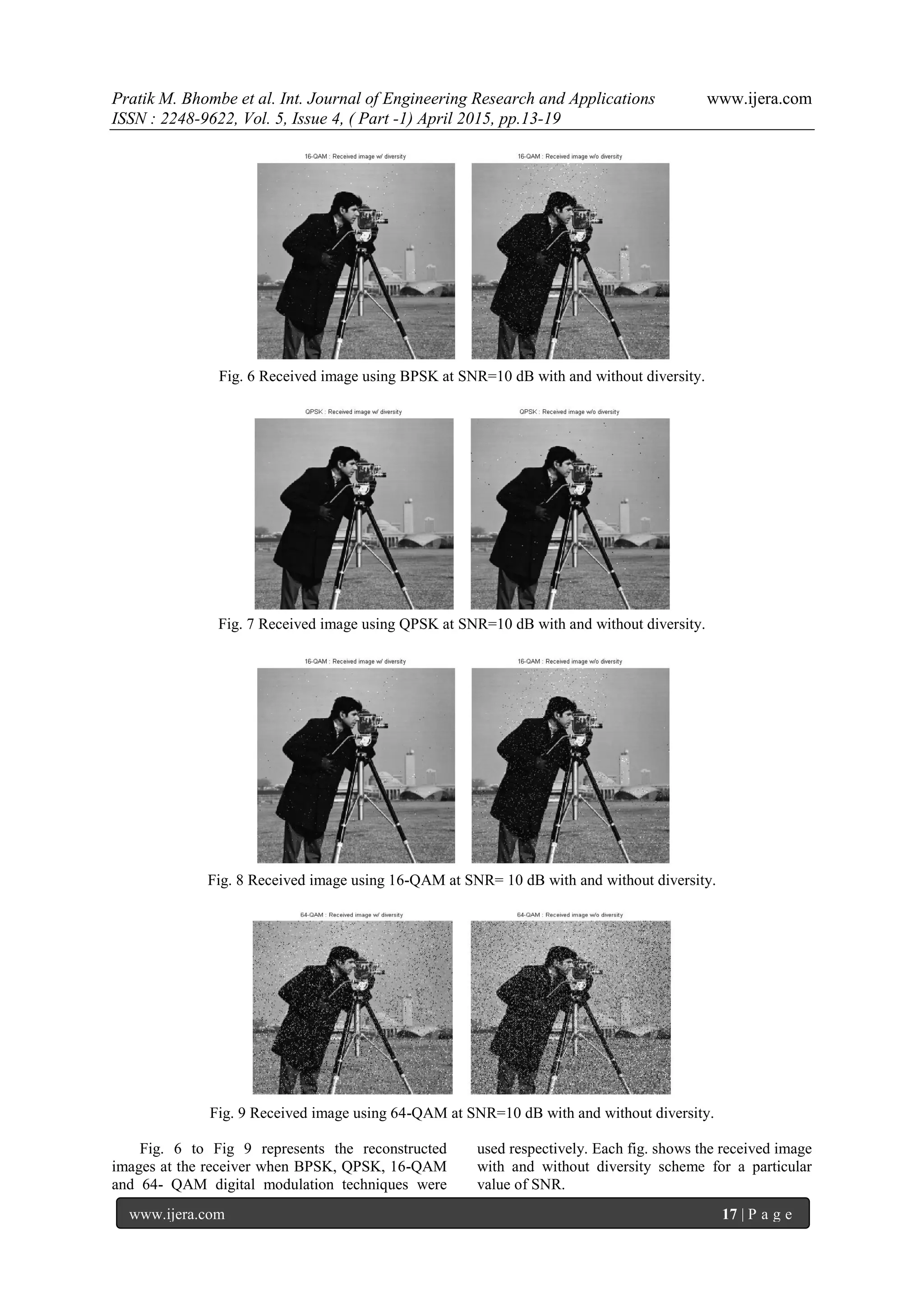
(reconstructed images) were obtained for BPSK in
terms of lowest BER for given value of SNR.
V. CONCLUSION
The paper demonstrates the transmission of
grayscale image using STBC and MIMO. A 2x2
MIMO System has been simulated and compared for
BPSK, QPSK, 16-QAM and 64-QAM digital
modulation techniques employed along with STBC
over Rayleigh fading environment. The effect of
noise on the received images in each case is observed
in terms of visual quality of the received image as
well as Bit Error rate (BER) vs. SNR plot.
It is observed that the effect of noise is
significantly reduced when diversity scheme is
employed as compared to images received without
using diversity in each case. This result is verified for
SNR= 10 dB for each of the four mentioned
modulation techniques.
From obtained results, it is clear that at a
particular value of SNR, Bit Error Rate (BER) is
lowest for BPSK and highest for 64-QAM. Similar
results are obtained in both cases i.e. for image
received with diversity and without. Thus for every
value of SNR, BER are in following decreasing
order with respect to modulation techniques:
64- QAM > 16-QAM > QPSK > BPSK
Fig. 9 BER vs. SNR plot for all four modulation techniques with and without diversity
Also it can be concluded that to achieve a certain
BER, signal power requirement is minimum for
BPSK and maximum for 64-QAM. Thus for systems
in which power constraints is a major issue, BPSK
modulation produces least noise at low signal
strength, giving better quality of signal transmission.
But the higher order modulation techniques like
QAM packs more number of bits per symbol and thus
increases the data rate but reduces the reliability of
the received file. Thus a suitable modulation
technique has to be selected in order to achieve a
tradeoff between speed, quality of reception and
power requirements.
REFERENCES
[1] Siavash M. Alamouti, A Simple Transmit
Diversity Technique for Wireless
Communications, IEEE Journal On Select
Areas In Communications, Vol. 16, No. 8,
October 1998.
[2] Mohinder Jankiraman, Space Time Codes
and MIMO Systems (685 Canton Street
Norwood, MA 02062 ,ISBN 1-58053-865-7)
[3] Luis Miguel Cort´es-Pe˜na, MIMO Space-
Time Block Coding (STBC): Simulations
and Results, Personal and Mobile
Communications, Georgia Tech (ECE6604),
April 2009.](https://image.slidesharecdn.com/c504011319-150414045252-conversion-gate01/75/Grayscale-Image-Transmission-over-Rayleigh-Fading-Channel-in-a-MIMO-System-Using-Different-Digital-Modulation-Techniques-with-STBC-6-2048.jpg)
![Pratik M. Bhombe et al. Int. Journal of Engineering Research and Applications www.ijera.com
ISSN : 2248-9622, Vol. 5, Issue 4, ( Part -1) April 2015, pp.13-19
www.ijera.com 19 | P a g e
[4] Shubhangi Chaudhary and A J Patil,
Performance analysis of MIMO-space time
block coding with different modulation
techniques, ICTACT Journal On
Communication Technology, March 2012,
Volume: 03, Issue: 01.
[5] Andrea Conti, Moe Z. Win and Marco
Chiani, Slow adaptive M-QAM with
diversity in fast fading and shadowing,
IEEE Transactions On Communications,
Vol. 55, No. 5, May 2007.
[6] William Stallings, Wireless Communications
and Networks, (2nd Edition, Upper Saddle
River, NJ 07458.)
[7] Ms. Shruti Helonde and Prof. M. S. Pawar,
BPSK Modulation Technique For Digital
Communication, International Journal of
Advanced Technology & Engineering
Research (IJATER) ISSN No: 2250-3536.
[8] Pankaj Sharma, Evolution of Mobile
Wireless communication Networks -1G to
5G as well as Future Prospective of Next
Generation Communication Network ,
International Journal of Computer Science
and Mobile Computing ,Vol. 2, Issue. 8,
August 2013, pg.47 – 53.
[9] Ashu Tuli, Narender Kumar, Kanchan
Sharma, Image Transmission using M-
QAM OFDM System over Composite
Fading Channel, IOSR Journal of
Electronics and Communication
Engineering (IOSR-JECE) e-ISSN: 2278-
2834, p- ISSN: 2278-8735.Volume 9, Issue
5, Ver. 1 (Sep - Oct. 2014), PP 69-77.
[10] Md. Zillur Rahman, Mamun Hossen and
Md. Abdur Razzak Joni, BER Performance
analysis for different multilevel modulating
technique under Rayleigh fading channel,
International Journal of Science,
Engineering and Technology Research
(IJSETR) Volume 2, Issue 10, October 2013.
[11] Raghunandan Swain, Ajit Kumar Panda,
Design of 16-QAM Transmitter and
Receiver: Review of Methods of
Implementation in FPGA, International
Journal of Engineering and Science, ISSN:
2278-4721, Vol. 1, Issue 9 (November
2012), PP 23-27.
[12] Ariel Bleicher, 4G gets real, Spectrum, IEEE
(Volume: 51, Issue: 1), January 2014.](https://image.slidesharecdn.com/c504011319-150414045252-conversion-gate01/75/Grayscale-Image-Transmission-over-Rayleigh-Fading-Channel-in-a-MIMO-System-Using-Different-Digital-Modulation-Techniques-with-STBC-7-2048.jpg)

The document discusses grayscale image transmission over a Rayleigh fading channel using a 2x2 MIMO system and various digital modulation techniques, including BPSK, QPSK, 16-QAM, and 64-QAM, focusing on enhancing bit error rate (BER) performance. It explains the use of Alamouti's space-time block coding for achieving diversity gain, and evaluates the effectiveness of different modulation methods in terms of BER against signal-to-noise ratio (SNR). The findings indicate significant improvements in transmission quality through MIMO systems, which can effectively combat multipath fading and enhance data rates without increasing bandwidth or transmit power.


![[Year 2012-13] Mimo technology](https://cdn.slidesharecdn.com/ss_thumbnails/mimotechnology-180701101303-thumbnail.jpg?width=640&height=640&fit=bounds)