Download to read offline


![14-50 Learning Autodesk Alias Design
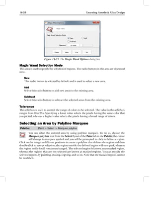
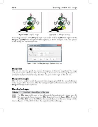
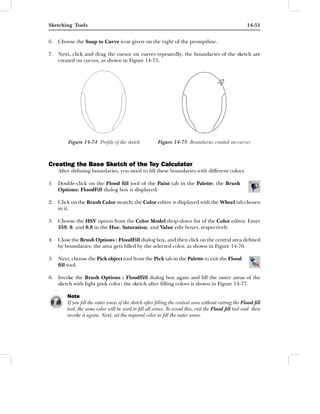
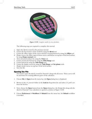
Figure 14-73 Sketch of a toy calculator
Starting Alias Design in the Paint Mode
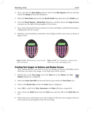
1. Double-click on the Alias 2012 icon on your desktop; the Design window is displayed.
2. Choose Preferences > Workflows > Paint from the menu bar; the Paint mode is invoked.
3. Choose File > New from the menu bar; the confirm message box is displayed.
4. Choose the Yes button from this message box; the New Canvas dialog box is displayed.
5. Next, choose the Top (Default) button from the Orientation area and then choose the
OK button from this dialog box; the Top [Paint] window expands to fill the entire screen.
Creating Curves and Boundaries
You need to create curves for defining the boundaries of the sketch.
1. Create the profile of the sketch by using different curve tools, as shown in Figure 14-74.
2. Double-click on the pencil tool from the Pencil flyout of the Paint tab in the
Palette with the Properties tab chosen.
3. Enter 1 in the Max Radius and Max Opacity edit boxes and then choose the Stamp tab
from this dialog box.
4. Press and hold the left mouse button on the Regular button in the Brush Profile
drop-down list; a flyout is displayed.
5. Select the Hard Solid option from the drop-down list and close the Brush
Options : PencilDefault dialog box.](https://image.slidesharecdn.com/c14aliasstudio2012-130411140058-phpapp01/85/C14-aliasstudio-2012-50-320.jpg)

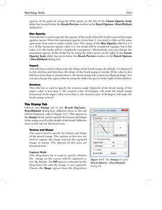
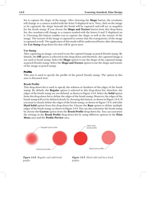
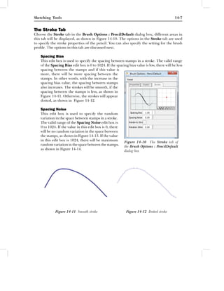
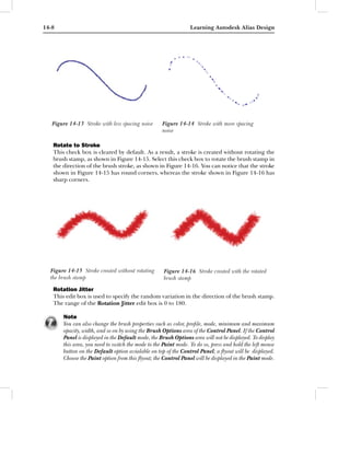
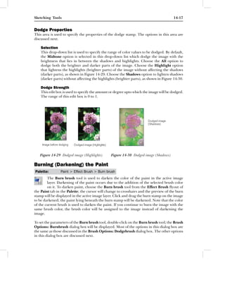
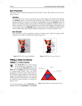
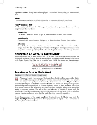
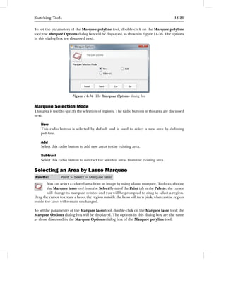
This document discusses sketching tools in Autodesk Alias Design. It describes various tools like pencils, markers, and brushes that can be used to sketch on the canvas. It explains how to set parameters for the pencil tool like color, opacity, radius, etc. through the Pencil Options dialog box. The document also covers options in the Stamp tab to specify texture, shape, and profile of the pencil stamp.


