Download as PDF, PPTX


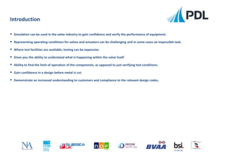
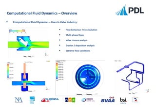
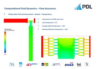
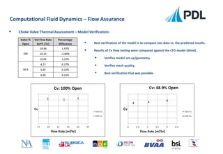
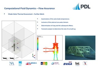


The document discusses the application of computational fluid dynamics (CFD) in assessing valve performance under extreme conditions. It highlights the advantages of simulation over traditional testing methods, including cost-effectiveness and the ability to predict flow behaviors, thermal properties, and verify designs before implementation. Additionally, the ongoing trends in the industry reflect an increasing demand for more detailed CFD analyses to mitigate risks and improve safety in valve operations.