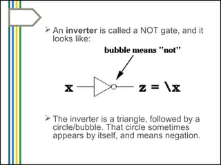
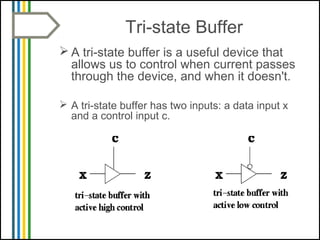
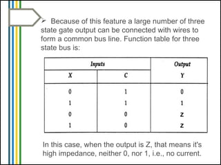
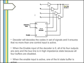
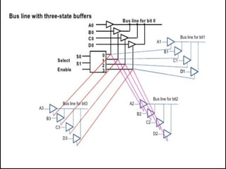
Bus Line Construction by
Tri-State Buffer
Presented By Farhana Shaikh
 An inverter is called a NOT gate, and it
looks like:
 The inverter is a triangle, followed by a
circle/bubble. That circle sometimes
appears by itself, and means negation.
 What if we remove the circle? What kind
of gate would we have? We'd have a
buffer.
 The output of buffer input is exactly
same. Thus, if the input, x is 0, the
output, z is 0. If the input, x is 1, the
output, z is 1.
 A tri-state buffer is a useful device that
allows us to control when current passes
through the device, and when it doesn't.
 A tri-state buffer has two inputs: a data input x
and a control input c.
Tri-state Buffer
 When the control input is active, the
output is the input. That is, it behaves just
like a normal buffer.
 When the control input is not active, the
output is "Z", and no electrical current
flows through. Thus, even if x is 0 or 1,
that value does not flow through.
 Because of this feature a large number of three
state gate output can be connected with wires to
form a common bus line. Function table for three
state bus is:
Z
Z
In this case, when the output is Z, that means it's
high impedance, neither 0, nor 1, i.e., no current.
Why Tri-State Buffers?
A common way for many devices to communicate
with one another is on a bus, and that a bus should
only have one device writing to it, although it can
have many devices reading from it.
Since many devices always produce output (such as
registers) and these devices are hooked to a bus, we
need a way to control what gets on the bus, and what
doesn't.
A tri state buffer is good for that.
Here's an example:
 There are three devices, each of which
output 32 bits. These devices have their
outputs hooked to a 32 bit bus.
Construct a Common Bus
Line with three state buffer
The construction of a bus system have four
buffers. The output of the four buffers are
connected together to form a single bus line.
At a particular time only one buffer is in active
state. The connected buffers must be
controlled so that only one tri state buffer has
access to the bus line while other buffers are
maintained in a high impedance.
• Decoder will decodes the codes in set of signals and it ensures
that no more than one control input is active.
• When the Enable input of the decoder is 0, all of its four outputs
are zero and the bus line is in high impedance state because all
four buffers are disabled.
• When the enable input is active, one of the tri state buffer is
active.
That's all.

Bus system

  • 1.
    Bus Line Constructionby Tri-State Buffer Presented By Farhana Shaikh
  • 2.
     An inverteris called a NOT gate, and it looks like:  The inverter is a triangle, followed by a circle/bubble. That circle sometimes appears by itself, and means negation.
  • 3.
     What ifwe remove the circle? What kind of gate would we have? We'd have a buffer.  The output of buffer input is exactly same. Thus, if the input, x is 0, the output, z is 0. If the input, x is 1, the output, z is 1.
  • 4.
     A tri-statebuffer is a useful device that allows us to control when current passes through the device, and when it doesn't.  A tri-state buffer has two inputs: a data input x and a control input c. Tri-state Buffer
  • 5.
     When thecontrol input is active, the output is the input. That is, it behaves just like a normal buffer.  When the control input is not active, the output is "Z", and no electrical current flows through. Thus, even if x is 0 or 1, that value does not flow through.
  • 6.
     Because ofthis feature a large number of three state gate output can be connected with wires to form a common bus line. Function table for three state bus is: Z Z In this case, when the output is Z, that means it's high impedance, neither 0, nor 1, i.e., no current.
  • 7.
    Why Tri-State Buffers? Acommon way for many devices to communicate with one another is on a bus, and that a bus should only have one device writing to it, although it can have many devices reading from it. Since many devices always produce output (such as registers) and these devices are hooked to a bus, we need a way to control what gets on the bus, and what doesn't. A tri state buffer is good for that.
  • 8.
    Here's an example: There are three devices, each of which output 32 bits. These devices have their outputs hooked to a 32 bit bus.
  • 9.
    Construct a CommonBus Line with three state buffer The construction of a bus system have four buffers. The output of the four buffers are connected together to form a single bus line. At a particular time only one buffer is in active state. The connected buffers must be controlled so that only one tri state buffer has access to the bus line while other buffers are maintained in a high impedance.
  • 10.
    • Decoder willdecodes the codes in set of signals and it ensures that no more than one control input is active. • When the Enable input of the decoder is 0, all of its four outputs are zero and the bus line is in high impedance state because all four buffers are disabled. • When the enable input is active, one of the tri state buffer is active.
  • 12.