Presentation to Washington Area CTO
Roundtable
Dr. David S. Yaney
Current Technologies
21 January, 2005
Current Communications Group / Current Technologies 2
Today’s agenda
 BPL Overview
 The Electricity Network
 CT Overhead System Architecture
 Power Line Channel
 OFDM
 Spectral Citizenship
 Industry Status and Next Steps
 Quiz
Current Communications Group / Current Technologies 3
What is BPL?
 “Broadband over Power Line” refers to high speed (multi-megabit)
unlicensed digital carrier current radio systems moving data over the
medium voltage (MV) and low voltage (LV) segments of a power line
network
– “in home” refers to operations akin to the LAN side of conventional networks
operating at the customer premise
– “access” refers to operations akin to the WAN side operating on the MV and LV
segments of the utility network
– The electric meter is the demarcation point
 A very attractive new business opportunity built between a Rock and Hard
Place
– The “rock” is FCC Part 15 Regulations
– The “hard place” is either noise or attenuation of the existing power networks
Current Communications Group / Current Technologies 4
Why Is BPL Attractive?
 Power lines are our most ubiquitous infrastructure
– In appropriate business relationships, their use can be essentially free
 Effective Broadband competition
– Potential 3rd
provider into home
– Existing wires – lower cost of deployment
 Potential for Enhanced Utility Services
– Adds “smart” capabilities to an otherwise “dumb” network
Current Communications Group / Current Technologies 5
Electricity Distribution Basics
Introduction
Power Plant Step-Up
Transformer
High Voltage
Lines
(69kV – 765 kV)
Substation Medium Voltage
Lines
(4kV – 46 kV)
Low Voltage
Lines
(120/240 V)
Generation Transmission
Example Companies
DistributionDistribution
From the transmission lines, the
voltage is stepped down at a
substation and distributed to
end-users over the local power grid
From the transmission lines, the
voltage is stepped down at a
substation and distributed to
end-users over the local power grid
Distribution
Current Communications Group / Current Technologies 6
Electricity System Layout
Current Communications Group / Current Technologies 7
Key Architectural Choices For BPL System
 Bypass Transformer or Pierce Transformer (MV to LV connectivity )
– Bypassing transformer allows lower and more predictable signal loss; piercing
requires no equipment
– Safety is paramount and bypass equipment is new for utilities
 Signal Repetition
– Regenerating data packets at various points allows greater reach at the
expense of lower bandwidth and greater latency
 Frequency Plan
– Selection of operating frequencies for backbone and service links
– FDD vs. TDD
– Coexistence with licensed services
 Bandwidth and latency
– Desired service offerings
– Latency sensitive applications – voice and gaming
Current Communications Group / Current Technologies 8
HomePlug®
CPE
HomePlug®
CPE
4
SolutionsSolutions
Internet
VoIP
CT Coupler®CT Coupler®
2
CT Backhaul-
Point®
CT Backhaul-
Point®
1
CT Bridge®CT Bridge®
3
CT View®
Management
System
CT View®
Management
System
5
ComponentsComponents
Medium-
voltage
lines
5
Low-voltage
lines
Backhau
l
2
1
2
3
4 4 4
CT Overhead System Architecture
Current Communications Group / Current Technologies 9
CT Bridge®
CT Coupler®
CT
Backhaul-
Point®
CT Overhead Installation
Current Communications Group / Current Technologies 10
3
2
Detailed CT Overhead Installation
Current Communications Group / Current Technologies 11
Power Line Is A Hostile Channel for Communications
 Power lines are full of
channel impairments
– Impedance Mismatch
– Unterminated Stubs
– Crosstalk
– Conducted Noise
– Ingress Noise
– Attenuation
– Frequency Selective
Characteristics
– Pesky high
voltage/current
– Variation over time
– Variation with weather
-90
-80
-70
-60
-50
-40
-30
-20
0 4 8 12 16 20 24 28
Channel Spectral Characteristics Post Ferrite Choke Insertion
Horizontal scale = Frequency (MHz)
Vertical Scale = Through Response (dB)
Current Communications Group / Current Technologies 12
OFDM Offers Superior Performance for BPL Applications
OFDM
Spread
Spectrum
Techniques (FH
and DS)
Single Carrier
Spectral
Efficiency
Good Moderate Moderate
Robustness
Against Channel
Distortions
Excellent Poor Good
Robustness
Against
Impulsive Noise
Fair Fair Good
Ability to adapt
to channel
changes
Excellent Fair Good
EMC Aspects Good Good-Excellent Poor
Implementation
Costs
(Equalizers, etc.)
Fair Poor
Poor (Equalizers
required)
Current Communications Group / Current Technologies 13
OFDM Signal Generation
•OFDM carriers are closely
spaced
•Note each carrier is placed
at the nulls of other carriers
OFDM systems are
practical with DSP
techniques
Single chip engines
available
Image: http://www.ert.rwth-
aachen.de/Projekte/Theo/OFDM/node6.html
Image: Communications Systems Design, Dec 2000
Current Communications Group / Current Technologies 14
OFDM System Example: Homeplug
 Homeplug is a standard for power line networking
– Used as the LV modem in Current’s solution
 84 carriers from 4.5-21 MHz – notches for amateur radio bands
-10
0
10
20
30
40
50
0 4 8 12 16 20 24 28
• Raw Throughout
14 Mbps
• Effective
throughput 6-7 Mbps
• DES encryption
• Products Widely
Available and Low
Cost
Current Communications Group / Current Technologies 15
Spectral Citizenship
 Some parties have expressed concern over potential interference to
licensed radio users
– Amateur radio operators most vocal opponents
 BPL power limits set by FCC Part 15 limits
– Formal FCC BPL R&O issued in October 2004
– Limits same as millions of other devices
– Verification/Certification must be done in situ
– Limits are extremely low
– Any resultant interference must be resolved by BPL operator
 Current’s Approach to Interference
– Avoidance is most effective mitigation technique
– Only one device on a link transmits at a time
– No overlap with amateur, broadcast, satellite frequencies
– Largest BPL deployment in North America
– No interference complaints
Current Communications Group / Current Technologies 16
Status of BPL Industry
 3 Commercial US Deployments
– Manassas, VA – Municipal utility – Main.Net
– Cincinnati, OH – Cinergy & Current Communications JV – Current Technologies
– Emmaus, PA – Pennsylvania Power & Light – Main.net and Amperion
30+ trial
deployments
in US
Commercial
deployments
in Germany,
Spain, Korea,
Chile, Brazil,
Image: Network
World, 23 Aug
2004
Current Communications Group / Current Technologies 17
Big Questions for BPL Industry
 Technical
– Verify scale - Technology works effectively. It now needs to demonstrate large
scale operation
 Non-technical
– Business Models - Industry business models need to be verified and shown to
work in actual commercial deployment
– Regulatory - BPL industry needs to show that regulatory issues can be handled
similar to other industries (cross-subsidization, etc.)
Current Communications Group / Current Technologies 18
Quiz
Calculate the temperature rise that a hard MV line fault to ground
would create if the energy was entirely dumped into 100 pounds of
water
Assume:
1. MV phase-to-phase voltage is 13.2 KV
2. The substation recloser will allow 10,000 amps for 10 cycles
Useful facts:
1. 1 joule almost exactly equals 1 watt-second
2. 1 joule equals approximately 0.24 calories
Hint: use CGS units
Current Communications Group / Current Technologies 19
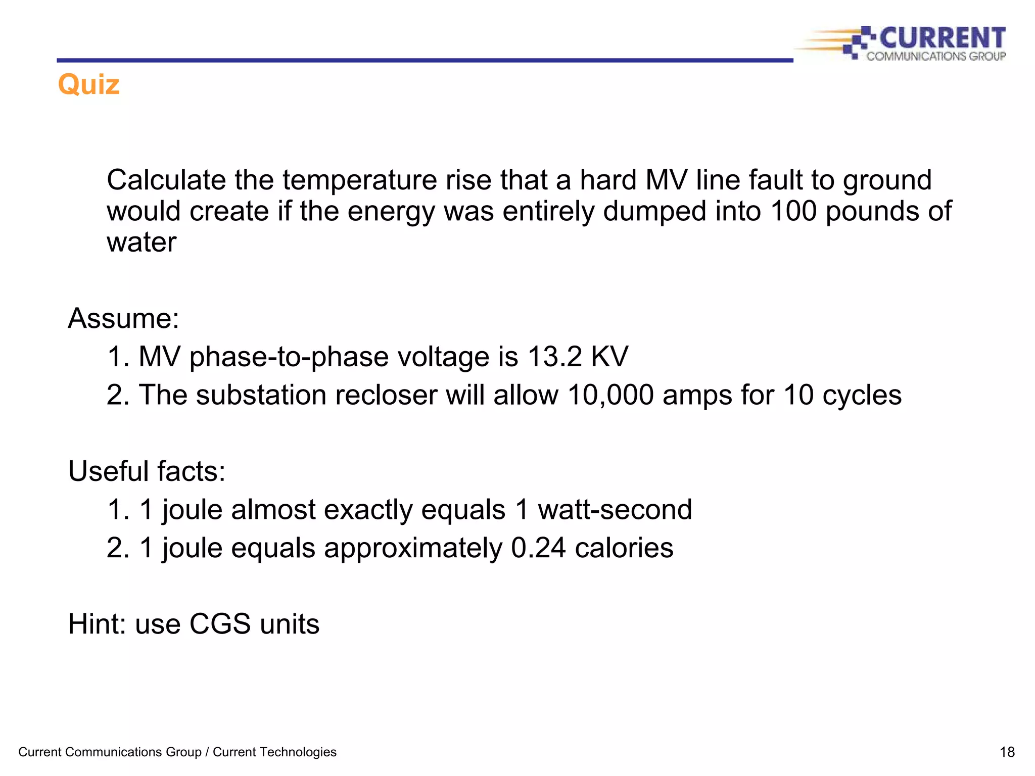
Quiz solution
The total energy Q dissipated as heat:
Q = (phase-ground voltage) * (current) * (time interval) [watt-seconds]
Q = (13.2 KV / 1.732) * (10,000 amps) * (160 msec) * (0.24) [calories]
Q = 2.93E06 calories
If that total energy is dumped into 100 pounds of water:
dT = Q / (mass of water * specific heat)
dT = 2.93E06 / (100 [lbs] * 454 [grams/lb] * 1 [cal/gram/deg C])
dT = 64.5C or 148F
It’s also interesting to note that:
dT/dt = (64.5/0.16) or about 400 degrees C / sec !

Broadband tech 2005

  • 1.
    Presentation to WashingtonArea CTO Roundtable Dr. David S. Yaney Current Technologies 21 January, 2005
  • 2.
    Current Communications Group/ Current Technologies 2 Today’s agenda  BPL Overview  The Electricity Network  CT Overhead System Architecture  Power Line Channel  OFDM  Spectral Citizenship  Industry Status and Next Steps  Quiz
  • 3.
    Current Communications Group/ Current Technologies 3 What is BPL?  “Broadband over Power Line” refers to high speed (multi-megabit) unlicensed digital carrier current radio systems moving data over the medium voltage (MV) and low voltage (LV) segments of a power line network – “in home” refers to operations akin to the LAN side of conventional networks operating at the customer premise – “access” refers to operations akin to the WAN side operating on the MV and LV segments of the utility network – The electric meter is the demarcation point  A very attractive new business opportunity built between a Rock and Hard Place – The “rock” is FCC Part 15 Regulations – The “hard place” is either noise or attenuation of the existing power networks
  • 4.
    Current Communications Group/ Current Technologies 4 Why Is BPL Attractive?  Power lines are our most ubiquitous infrastructure – In appropriate business relationships, their use can be essentially free  Effective Broadband competition – Potential 3rd provider into home – Existing wires – lower cost of deployment  Potential for Enhanced Utility Services – Adds “smart” capabilities to an otherwise “dumb” network
  • 5.
    Current Communications Group/ Current Technologies 5 Electricity Distribution Basics Introduction Power Plant Step-Up Transformer High Voltage Lines (69kV – 765 kV) Substation Medium Voltage Lines (4kV – 46 kV) Low Voltage Lines (120/240 V) Generation Transmission Example Companies DistributionDistribution From the transmission lines, the voltage is stepped down at a substation and distributed to end-users over the local power grid From the transmission lines, the voltage is stepped down at a substation and distributed to end-users over the local power grid Distribution
  • 6.
    Current Communications Group/ Current Technologies 6 Electricity System Layout
  • 7.
    Current Communications Group/ Current Technologies 7 Key Architectural Choices For BPL System  Bypass Transformer or Pierce Transformer (MV to LV connectivity ) – Bypassing transformer allows lower and more predictable signal loss; piercing requires no equipment – Safety is paramount and bypass equipment is new for utilities  Signal Repetition – Regenerating data packets at various points allows greater reach at the expense of lower bandwidth and greater latency  Frequency Plan – Selection of operating frequencies for backbone and service links – FDD vs. TDD – Coexistence with licensed services  Bandwidth and latency – Desired service offerings – Latency sensitive applications – voice and gaming
  • 8.
    Current Communications Group/ Current Technologies 8 HomePlug® CPE HomePlug® CPE 4 SolutionsSolutions Internet VoIP CT Coupler®CT Coupler® 2 CT Backhaul- Point® CT Backhaul- Point® 1 CT Bridge®CT Bridge® 3 CT View® Management System CT View® Management System 5 ComponentsComponents Medium- voltage lines 5 Low-voltage lines Backhau l 2 1 2 3 4 4 4 CT Overhead System Architecture
  • 9.
    Current Communications Group/ Current Technologies 9 CT Bridge® CT Coupler® CT Backhaul- Point® CT Overhead Installation
  • 10.
    Current Communications Group/ Current Technologies 10 3 2 Detailed CT Overhead Installation
  • 11.
    Current Communications Group/ Current Technologies 11 Power Line Is A Hostile Channel for Communications  Power lines are full of channel impairments – Impedance Mismatch – Unterminated Stubs – Crosstalk – Conducted Noise – Ingress Noise – Attenuation – Frequency Selective Characteristics – Pesky high voltage/current – Variation over time – Variation with weather -90 -80 -70 -60 -50 -40 -30 -20 0 4 8 12 16 20 24 28 Channel Spectral Characteristics Post Ferrite Choke Insertion Horizontal scale = Frequency (MHz) Vertical Scale = Through Response (dB)
  • 12.
    Current Communications Group/ Current Technologies 12 OFDM Offers Superior Performance for BPL Applications OFDM Spread Spectrum Techniques (FH and DS) Single Carrier Spectral Efficiency Good Moderate Moderate Robustness Against Channel Distortions Excellent Poor Good Robustness Against Impulsive Noise Fair Fair Good Ability to adapt to channel changes Excellent Fair Good EMC Aspects Good Good-Excellent Poor Implementation Costs (Equalizers, etc.) Fair Poor Poor (Equalizers required)
  • 13.
    Current Communications Group/ Current Technologies 13 OFDM Signal Generation •OFDM carriers are closely spaced •Note each carrier is placed at the nulls of other carriers OFDM systems are practical with DSP techniques Single chip engines available Image: http://www.ert.rwth- aachen.de/Projekte/Theo/OFDM/node6.html Image: Communications Systems Design, Dec 2000
  • 14.
    Current Communications Group/ Current Technologies 14 OFDM System Example: Homeplug  Homeplug is a standard for power line networking – Used as the LV modem in Current’s solution  84 carriers from 4.5-21 MHz – notches for amateur radio bands -10 0 10 20 30 40 50 0 4 8 12 16 20 24 28 • Raw Throughout 14 Mbps • Effective throughput 6-7 Mbps • DES encryption • Products Widely Available and Low Cost
  • 15.
    Current Communications Group/ Current Technologies 15 Spectral Citizenship  Some parties have expressed concern over potential interference to licensed radio users – Amateur radio operators most vocal opponents  BPL power limits set by FCC Part 15 limits – Formal FCC BPL R&O issued in October 2004 – Limits same as millions of other devices – Verification/Certification must be done in situ – Limits are extremely low – Any resultant interference must be resolved by BPL operator  Current’s Approach to Interference – Avoidance is most effective mitigation technique – Only one device on a link transmits at a time – No overlap with amateur, broadcast, satellite frequencies – Largest BPL deployment in North America – No interference complaints
  • 16.
    Current Communications Group/ Current Technologies 16 Status of BPL Industry  3 Commercial US Deployments – Manassas, VA – Municipal utility – Main.Net – Cincinnati, OH – Cinergy & Current Communications JV – Current Technologies – Emmaus, PA – Pennsylvania Power & Light – Main.net and Amperion 30+ trial deployments in US Commercial deployments in Germany, Spain, Korea, Chile, Brazil, Image: Network World, 23 Aug 2004
  • 17.
    Current Communications Group/ Current Technologies 17 Big Questions for BPL Industry  Technical – Verify scale - Technology works effectively. It now needs to demonstrate large scale operation  Non-technical – Business Models - Industry business models need to be verified and shown to work in actual commercial deployment – Regulatory - BPL industry needs to show that regulatory issues can be handled similar to other industries (cross-subsidization, etc.)
  • 18.
    Current Communications Group/ Current Technologies 18 Quiz Calculate the temperature rise that a hard MV line fault to ground would create if the energy was entirely dumped into 100 pounds of water Assume: 1. MV phase-to-phase voltage is 13.2 KV 2. The substation recloser will allow 10,000 amps for 10 cycles Useful facts: 1. 1 joule almost exactly equals 1 watt-second 2. 1 joule equals approximately 0.24 calories Hint: use CGS units
  • 19.
    Current Communications Group/ Current Technologies 19 Quiz solution The total energy Q dissipated as heat: Q = (phase-ground voltage) * (current) * (time interval) [watt-seconds] Q = (13.2 KV / 1.732) * (10,000 amps) * (160 msec) * (0.24) [calories] Q = 2.93E06 calories If that total energy is dumped into 100 pounds of water: dT = Q / (mass of water * specific heat) dT = 2.93E06 / (100 [lbs] * 454 [grams/lb] * 1 [cal/gram/deg C]) dT = 64.5C or 148F It’s also interesting to note that: dT/dt = (64.5/0.16) or about 400 degrees C / sec !