SlideShare a Scribd company logo
Arduino Nano
Arduino Nano Development Board
Arduino Nano Pin Diagram
The Arduino Nano is another popular Arduino development board very much similar
to the Arduino UNO. They use the same Processor (Atmega328p) and hence they both
can share the same program.
Table 1
Pin Category Pin Name Details
Power Vin, 3.3V, 5V, GND Vin: Input voltage to Arduino when using an external power
source (6-12V).
5V: Regulated power supply used to power microcontroller
and other components on the board.
3.3V: 3.3V supply generated by on-board voltage regulator.
Maximum current draw is 50mA.
GND: Ground pins.
Reset Reset Resets the microcontroller.
Analog Pins A0 – A7 Used to measure analog voltage in the range of 0-5V
Input/Output
Pins
Digital Pins D0 - D13 Can be used as input or output pins. 0V (low) and 5V (high)
Serial Rx, Tx Used to receive and transmit TTL serial data.
External
Interrupts
2, 3 To trigger an interrupt.
PWM 3, 5, 6, 9, 11 Provides 8-bit PWM output.
SPI 10 (SS), 11 (MOSI), 12
(MISO) and 13 (SCK)
Used for SPI communication.
Inbuilt LED 13 To turn on the inbuilt LED.
IIC A4 (SDA), A5 (SCA) Used for TWI communication.
AREF AREF To provide a reference voltage for input voltage.
Arduino Nano Pinout Configuration
Arduino Nano Technical Specifications
Microcontroller ATmega328P – 8-bit AVR family microcontroller
Operating Voltage 5V
Recommended Input Voltage for Vin pin 7-12V
Analog Input Pins 6 (A0 – A5)
Digital I/O Pins 14 (Out of which 6 provide PWM output)
DC Current on I/O Pins 40 mA
DC Current on 3.3V Pin 50 mA
Flash Memory 32 KB (2 KB is used for Bootloader)
SRAM 2 KB
EEPROM 1 KB
Frequency (Clock Speed) 16 MHz
Communication IIC, SPI, USART
Other Arduino Boards
Arduino UNO, Arduino Pro Mini, Arduino Mega, Arduino Due, Arduino MKR1000 Wi-
Fi Board, Arduino Leonardo
Other Development Boards
Raspberry Pi, PIC Development Board, AVR Development Board, MSP430
Launchpad, TEENSY 3.6 Development Board, Intel Edison, ESP32, STM32F103C8T6 -
Blue Pill Development Board, NodeMCU ESP8266
Difference between Arduino UNO and Arduino Nano
Name Processor Operating/Input
Voltage
CPU
speed
Analog
In/Out
Digital
IO/PWM
EEPROM /
SRAM[kB]
Flash USB USART
The Arduino Nano is very much similar to the Arduino UNO. They use the same
Processor (Atmega328p) and hence they both can share the same program. One big
difference between both is the size. UNO is twice as big as Nano and hence occupies
more space on your project. Also, Nano is breadboard friendly while Uno is not. To
program an Uno, you need a Regular USB cable; whereas for Nano, you will need a
mini USB cable. The technical difference between Uno and Nano is shown below:
Difference between Arduino Nano and Arduino Mega
There is a considerable amount of difference between the Arduino Nano and the
Arduino mega as the processor used itself is different. Arduino Mega is more powerful
than an Arduino Nano in terms of speed and number of I/O pins. As you might guess,
the size is also bigger than an Arduino UNO. Arduino Mega is normally used for
projects which require a lot of I/O pins and different communication protocols. The
technical difference between Nano and Mega is shown below.
Name Processor Operating/Input
Voltage
CPU
speed
Analog
In/Out
Digital
IO/PWM
EEPROM /
SRAM[kB]
Flash U
Mega ATmega2560 5V / 7-12V 16
MHz
16 / 0 54 / 15 4 / 8 256 R
Uno ATmega328P 5V / 7-12V 16
MHz
6 / 0 14 / 6 1 / 2 32 Regular 1
Nano ATmega328P 5V / 7-12V 16
MHz
8 / 0 14 / 6 1 / 2 32 Mini 1
Nano ATmega328P 5V / 7-12V 16
MHz
8 / 0 14 / 6 1 / 2 32 M
Understanding Arduino Nano
The Arduino board is designed in such a way that it is very easy for beginners to get
started with microcontrollers. This board especially is breadboard friendly, and that's
why it is very easy to handle the connections. Let’s start with powering the Board.
Powering you Arduino Nano:
There are total three ways by which you can power your Nano.
USB Jack: Connect the mini USB jack to a phone charger or computer through a cable
and it will draw power required for the board to function
Vin Pin: The Vin pin can be supplied with an unregulated 6-12V to power the board.
The on-board voltage regulator regulates it to +5V.
+5V Pin: If you have a regulated +5V supply then you can directly provide this o the
+5V pin of the Arduino.
Input/output:
There are total 14 digital Pins and 8 Analog pins on your Nano board. The digital pins
can be used to interface sensors by using them as input pins or drive loads by using
them as output pins. A simple function like pinMode() and digitalWrite() can be
used to control their operation. The operating voltage is 0V and 5V for digital pins. The
analog pins can measure analog voltage from 0V to 5V using any of the 8 Analog pins
using a simple function like analogRead().
These pins apart from serving their purpose, can also be used for special purposes,
which are discussed below:
 Serial Pins 0 (Rx) and 1 (Tx): Rx and Tx pins are used to receive and
transmit TTL serial data. They are connected with the corresponding
ATmega328P USB to TTL serial chip.
 External Interrupt Pins 2 and 3: These pins can be configured to trigger
an interrupt on a low value, a rising or falling edge, or a change in value.
 PWM Pins 3, 5, 6, 9 and 11: These pins provide an 8-bit PWM output by
using analogWrite() function.
 SPI Pins 10 (SS), 11 (MOSI), 12 (MISO) and 13 (SCK): These pins are used
for SPI communication.
 In-built LED Pin 13: This pin is connected with a built-in LED. When pin 13
is HIGH – LED is on and when pin 13 is LOW, it is off.
 I2C A4 (SDA) and A5 (SCA): Used for IIC communication using Wire
library.
 AREF: Used to provide reference voltage for analog inputs
with analogReference() function.
 Reset Pin: Making this pin LOW, resets the microcontroller.
These special functions and their respective pins are illustrated in the Arduino Nano
pinout diagram shown above.
How to use Arduino Nano
It will hardly take 5-10 minutes to upload your first program to Arduino Nano. All
you need the Arduino IDE, an USB cable and your Nano board itself.
Download and Install Arduino:
The first step would be to install the Arduino IDE which is available for download for
free from the below link. After installing Arduino, you might also want to install the
drivers (link given below) for your Arduino to communicate with your Computer.
 Arduino IDE Download
 Driver Download
Uploading your first program
Once arduino IDE is installed on the computer, connect the board with computer using
USB cable. Now open the arduino IDE and choose the correct board by
selecting Tools>Boards>Arduino/Nano, and choose the correct Port by
selecting Tools>Port. Arduino Uno is programmed using Arduino programming
language based on Wiring. To get it started with Arduino Uno board and blink the
built-in LED, load the example code by selecting Files>Examples>Basics>Blink.Once
the example code (also shown below) is loaded into your IDE, click on the ‘upload’
button given on the top bar. Once the upload is finished, you should see the Arduino’s
built-in LED blinking. Below is the example code for blinking:
// the setup function runs once when you press reset or power the board
void setup() {
// initialize digital pin LED_BUILTIN as an output.
pinMode(LED_BUILTIN, OUTPUT);
}
// the loop function runs over and over again forever
void loop() {
digitalWrite(LED_BUILTIN, HIGH); // turn the LED on (HIGH is the voltage level
)
delay(1000); // wait for a second
digitalWrite(LED_BUILTIN, LOW); // turn the LED off by making the voltage LOW
delay(1000); // wait for a second
}
Applications
 Prototyping of Electronics Products and Systems
 Multiple DIY Projects.
 Easy to use for beginner-level DIYers and makers.
 Projects requiring Multiple I/O interfaces and communications.
IR Sensor Module
IR Sensor/Obstacle Sensor Module
IR Sensor Module Pinout
IR Sensor Module Pinout Configuration
Pin Name Description
VCC Power Supply Input
GND Power Supply Ground
OUT Active High Output
IR Sensor Module Features
 5VDC Operating voltage
 I/O pins are 5V and 3.3V compliant
 Range: Up to 20cm
 Adjustable Sensing range
 Built-in Ambient Light Sensor
 20mA supply current
 Mounting hole
Brief about IR Sensor Module
The IR sensor module consists mainly of the IR Transmitter and Receiver, Op-amp,
Variable Resistor (Trimmer pot), output LED along with few resistors.
IR LED Transmitter
IR LED emits light, in the range of Infrared frequency. IR light is invisible to us as its
wavelength (700nm – 1mm) is much higher than the visible light range. IR LEDs have
light emitting angle of approx. 20-60 degree and range of approx. few centimeters to
several feets, it depends upon the type of IR transmitter and the manufacturer. Some
transmitters have the range in kilometers. IR LED white or transparent in colour, so it
can give out amount of maximum light.
Photodiode Receiver
Photodiode acts as the IR receiver as its conducts when light falls on it. Photodiode is
a semiconductor which has a P-N junction, operated in Reverse Bias, means it start
conducting the current in reverse direction when Light falls on it, and the amount of
current flow is proportional to the amount of Light. This property makes it useful for
IR detection. Photodiode looks like a LED, with a black colour coating on its outer side,
Black colour absorbs the highest amount of light.
LM358 Opamp
LM358 is an Operational Amplifier (Op-Amp) is used as voltage comparator in the IR
sensor. the comparator will compare the threshold voltage set using the preset (pin2)
and the photodiode’s series resistor voltage (pin3).
Photodiode’s series resistor voltage drop > Threshold voltage = Opamp output is High
Photodiode’s series resistor voltage drop < Threshold voltage = Opamp output is Low
When Opamp's output is high the LED at the Opamp output terminal turns
ON (Indicating the detection of Object).
Variable Resistor
The variable resistor used here is a preset. It is used to calibrate the distance range at
which object should be detected.
How to Use IR Sensor Module?
The 5 VDC supply input is given to the VCC pin and the supply negative is connected
to the GND terminal of the module. When no object is detected within the range of
the IR receiver, the output LED remains off.
When a object is detected within the range of the IR sensor the LED glows.
Applications
 Obstacle Detection
 Industrial safety devices
 Wheel encoder
2D-Model
MQ-135 - Gas Sensor for Air Quality
MQ-135 Gas Sensor/Module
MQ-135 Gas Sensor Pinout
Pin Configuration:
Pin
No:
Pin Name: Description
For Module
1 Vcc Used to power the sensor, Generally the operating voltage is +5V.
2 Ground Used to connect the module to system ground.
3 Digital
Out
You can also use this sensor to get digital output from this pin, by setting a t
value using the potentiometer.
4 Analog
Out
This pin outputs 0-5V analog voltage based on the intensity of the gas.
For Sensor
1 H -Pins Out of the two H pins, one pin is connected to supply and the other to groun
2 A-Pins The A pins and B pins are interchangeable. These pins will be tied to the Supply
3 B-Pins
20. A pins and B pins are interchangeable. One pin will act as output while the ot
be pulled to ground.
MQ-135 Sensor Features
 Wide detecting scope
 Fast response and High sensitivity
 Stable and long life
 Operating Voltage is +5V
 Detect/Measure NH3, NOx, alcohol, Benzene, smoke, CO2, etc.
 Analog output voltage: 0V to 5V
 Digital output voltage: 0V or 5V (TTL Logic)
 Preheat duration 20 seconds
 Can be used as a Digital or analog sensor
 The Sensitivity of Digital pin can be varied using the potentiometer
Note: Complete technical information can be found in the MQ-135 Datasheet linked
a the bottom of this page.
Alternative MQ Gas sensors
Sensor Name Gas to measure
MQ-2 Methane, Butane, LPG, Smoke
MQ-3 Alcohol, Ethanol, Smoke
MQ-4 Methane, CNG Gas
MQ-5 Natural gas, LPG
MQ-6 LPG, butane
MQ-7 Carbon Monoxide
MQ-8 Hydrogen Gas
MQ-9 Carbon Monoxide, flammable gasses
MQ131 Ozone
MQ135 Air Quality
MQ136 Hydrogen Sulphide gas
MQ137 Ammonia
MQ138 Benzene, Toluene, Alcohol, Propane, Formaldehyde gas, Hydrogen
MQ214 Methane, Natural Gas
MQ216 Natural gas, Coal Gas
MQ303A Alcohol, Ethanol, smoke
MQ306A LPG, butane
MQ307A Carbon Monoxide
MQ309A Carbon Monoxide, flammable gas
Selecting between sensor and module
When it comes to measuring or detecting a particular Gas, the MQ series Gas
sensors are the most inexpensive and commonly used ones. MQ135 is available as a
module or as just the sensor alone. If you are trying to only detect (not measuring
PPM) the presence of a gas, then you can buy it as a module since it comes with an
op-amp comparator and a digital output pin. But if you planning to measure the PPM
of a gas it is recommend buying the sensor alone without module.
Where to use MQ-135 Gas sensor
The MQ-135 Gas sensors are used in air quality control equipments and are suitable
for detecting or measuring of NH3, NOx, Alcohol, Benzene, Smoke, CO2. The MQ-135
sensor module comes with a Digital Pin which makes this sensor to operate even
without a microcontroller and that comes in handy when you are only trying to detect
one particular gas. If you need to measure the gases in PPM, the analog pin need to
be used. The analog pin is TTL driven and works on 5V and so can be used with most
common microcontrollers.
If you are looking for a sensor to detect or measure common air quality gases such as
CO2, Smoke, NH3, NOx, Alcohol, Benzene then this sensor might be the right choice
for you.
How to use MQ-135 Sensors to detect gases
You can either use the digital pin or the analog pin to do this. Simplypower the module
with 5V and you should notice the power LED on the module to glow and when no
gas it detected the output LED will remain turned off meaning the digital output pin
will be 0V. Remember that these sensors have to be kept on for pre-heating time
(mentioned in features above) before you can actually work with it. Now, introduce the
sensor to the gas you want to detect and you should see the output LED to go high
along with the digital pin, if not use the potentiometer until the output gets high. Now
every time your sensor gets introduced to this gas at this particular concentration the
digital pin will go high (5V) else will remain low (0V).
You can also use the analog pin to achieve the same thing. Read the analog values (0-
5V) using a microcontroller, this value willbe directly proportional to the concentration
of the gas to which the sensor detects. You can experiment with this values and check
how the sensor reacts to different concentration of gas and develop your program
accordingly.
How to use MQ-135 sensor to measure PPM
MQ-135 gas sensor applies SnO2 which has a higher resistance in the clear air as a
gas-sensing material. When there is an increase in polluting gases, the resistance of
the gas sensor decreases along with that. To measure PPM using MQ-135 sensor we
need to look into the (Rs/Ro) v/s PPM graph taken from the MQ135 datasheet.
The above figure shows shows the typical sensitivity characteristics of the MQ-135 for
several gases. in their: Temp: 20, Humidity: 65%, O2 concentration 21%, RL=20kΩ,
Ro: sensor resistance at 100ppm of NH3 in the clean air.
Rs:sensor resistance at various concentrations of gases.
The value of Ro is the value of resistance in fresh air (or the air with we are comparing)
and the value of Rs is the value of resistance in Gas concentration. First you should
calibrate the sensor by finding the values of Ro in fresh air and then use that value to
find Rs using the below formula:
Once we calculate Rs and Ro we can find the ratio and then using the graph shown
above we can calculate the equivalent value of PPM for that particular gas.
Applications:
 Used to detect leakage/excess of gases like Ammonia, nitrogen oxide,
alcohols, aromatic compounds, sulfide and smoke.
 Air quality monitors.
2D model of MQ-135 Gas sensor
Use the following MQ135 sensor dimensions to create your own PCB for your
application.
HC-SR04 Ultrasonic Sensor
HC-SR04 Ultrasonic Sensor Module
HC-SR04 Ultrasonic Sensor Pinout
Ultrasonic Sensor Pinout Configuration
Pin
Number
Pin
Name
Description
1 Vcc The Vcc pin powers the sensor, typically with +5V
2 Trigger Trigger pin is an Input pin. This pin has to be kept high for 10us to
measurement by sending US wave.
3 Echo Echo pin is an Output pin. This pin goes high for a period of time which will
to the time taken for the US wave to return back to the sensor.
4 Ground This pin is connected to the Ground of the system.
HC-SR04 Sensor Features
 Operating voltage: +5V
 Theoretical Measuring Distance: 2cm to 450cm
 Practical Measuring Distance: 2cm to 80cm
 Accuracy: 3mm
 Measuring angle covered: <15°
 Operating Current: <15mA
 Operating Frequency: 40Hz
More details can be found in the HC-SR04 ultrasonic sensor datasheet attached at
the bottom of this article.
Equivalent distance measuring Sensors
US transmitter Receiver pair, IR sensor module, IR sensor pair, IR Analog distance
sensor,
HC-SR04 Ultrasonic Sensor - Working
As shown above the HC-SR04 Ultrasonic (US) sensor is a 4 pin module, whose pin
names are Vcc, Trigger, Echo and Ground respectively. This sensor is a very popular
sensor used in many applications where measuring distance or sensing objects are
required. The module has two eyes like projects in the front which forms the Ultrasonic
transmitter and Receiver. The sensor works with the simple high school formula that
Distance = Speed × Time
The Ultrasonic transmitter transmits an ultrasonic wave, this wave travels in air and
when it gets objected by any material it gets reflected back toward the sensor this
reflected wave is observed by the Ultrasonic receiver module as shown in the picture
below
Now, to calculate the distance using the above formulae, we should know the Speed
and time. Since we are using the Ultrasonic wave we know the universal speed of US
wave at room conditions which is 330m/s. The circuitry inbuilt on the module will
calculate the time taken for the US wave to come back and turns on the echo pin high
for that same particular amount of time, this way we can also know the time taken.
Now simply calculate the distance using a microcontroller or microprocessor.
How to use the HC-SR04 Ultrasonic Sensor
HC-SR04 distance sensor is commonly used with both microcontroller and
microprocessor platforms like Arduino, ARM, PIC, Raspberry Pie etc. The following
guide is universallysince it has to be followed irrespective of the type of computational
device used.
Power the Sensor using a regulated +5V through the Vcc ad Ground pins of the
sensor. The current consumed by the sensor is less than 15mA and hence can be
directly powered by the on board 5V pins (If available). The Trigger and the Echo pins
are both I/O pins and hence they can be connected to I/O pins of the microcontroller.
To start the measurement, the trigger pin has to be made high for 10uS and then
turned off. This action will trigger an ultrasonic wave at frequency of 40Hz from the
transmitter and the receiver will wait for the wave to return. Once the wave is returned
after it getting reflected by any object the Echo pin goes high for a particular amount
of time which will be equal to the time taken for the wave to return back to the sensor.
The amount of time during which the Echo pin stays high is measured by the
MCU/MPU as it gives the information about the time taken for the wave to return back
to the Sensor. Using this information the distance is measured as explained in the
above heading.
Applications
 Used to avoid and detect obstacles with robots like biped robot, obstacle avoider
robot, path finding robot etc.
 Used to measure the distance within a wide range of 2cm to 400cm
 Can be used to map the objects surrounding the sensor by rotating it
 Depth of certain places like wells, pits etc can be measured since the waves can
penetrate through water
2D model of the component
DHT11–Temperature and Humidity Sensor
DHT11 Sensor Pinout
The DHT11 is a commonly used Temperature and humidity sensor that comes with
a dedicated NTC to measure temperature and an 8-bit microcontroller to output the
values of temperature and humidity as serial data.
DHT11 Pinout Configuration
No: Pin Name Description
For DHT11 Sensor
1 Vcc Power supply 3.5V to 5.5V
2 Data Outputs both Temperature and Humidity through serial Data
3 NC No Connection and hence not used
4 Ground Connected to the ground of the circuit
For DHT11 Sensor module
1 Vcc Power supply 3.5V to 5.5V
2 Data Outputs both Temperature and Humidity through serial Data
3 Ground Connected to the ground of the circuit
You can buy DHT11 sensor module from here.
DHT11 Specifications
 Operating Voltage: 3.5V to 5.5V
 Operating current: 0.3mA (measuring) 60uA (standby)
 Output: Serial data
 Temperature Range: 0°C to 50°C
 Humidity Range: 20% to 90%
 Resolution: Temperature and Humidity both are 16-bit
 Accuracy: ±1°C and ±1%
Note: Complete technical details can be found in the DHT11 datasheet linked at the
bottom of the page.
DHT11 Equivalent Temperature Sensors
DHT22, AM2302, SHT71
Other Temperature Sensors:
Thermocouple, TMP100, LM75, DS18820, SHT15, LM35DZ, TPA81, D6T
Difference between DHT11 Sensor and Module
The DHT11 sensor can either be purchased as a sensor or as a module. Either way, the
performance of the sensor is same. The sensor will come as a 4-pin package out of
which only three pins will be used whereas the module will come with three pins as
shown above.
The only difference between the sensor and module is that the module will have a
filtering capacitor and pull-up resistor inbuilt, and for the sensor, you have to use them
externally if required.
Where to use DHT11 Sensors
The DHT11 is a commonly used Temperature and humidity sensor. The sensor
comes with a dedicated NTC to measure temperature and an 8-bit microcontroller to
output the values of temperature and humidity as serial data. The sensor is also factory
calibrated and hence easy to interface with other microcontrollers.
The sensor can measure temperature from 0°C to 50°C and humidity from 20% to 90%
with an accuracy of ±1°C and ±1%. So if you are looking to measure in this range then
this sensor might be the right choice for you.
How to use DHT11 Sensor
The DHT11 Sensor is factory calibrated and outputs serial data and hence it is highly
easy to set it up. The connection diagram for this sensor is shown below.
As you can see the data pin is connected to an I/O pin of the MCU and a 5K pull-up
resistor is used. This data pin outputs the value of both temperature and humidity as
serial data. If you are trying to interface DHT11 with Arduino then there are ready-
made libraries for it which will give you a quick start.
If you are trying to interface it with some other MCU, then the datasheet given below
will come in handy. The output given out by the data pin will be in the order of 8bit
humidity integer data + 8bit the Humidity decimal data +8 bit temperature integer
data + 8bit fractional temperature data +8 bit parity bit. To request the DHT11 module
to send these data the I/O pin has to be momentarily made low and then held high as
shown in the timing diagram below
The duration of each host signal is explained in the DHT11 datasheet, with neat steps
and illustrative timing diagrams
Applications
 Measure temperature and humidity
 Local Weather station
 Automatic climatecontrol
 Environment monitoring
2D–model and Dimensions
Neno Project.docx

More Related Content

Similar to Neno Project.docx

Arduino Uno Pin Description
Arduino Uno Pin DescriptionArduino Uno Pin Description
Arduino Uno Pin Description
Niket Chandrawanshi
 
Arduino windows remote control
Arduino windows remote controlArduino windows remote control
Arduino windows remote control
VilayatAli5
 
Chapter 5 Arduino Microcontroller Systems .pptx
Chapter 5 Arduino Microcontroller Systems .pptxChapter 5 Arduino Microcontroller Systems .pptx
Chapter 5 Arduino Microcontroller Systems .pptx
khgh7
 
Embedded system application
Embedded system applicationEmbedded system application
Embedded system application
Dhruwank Vankawala
 
Arduino arduino boarduno
Arduino   arduino boardunoArduino   arduino boarduno
Arduino arduino boardunoFilipe Campos
 
Smart Blind stick by using arduino uno and sensor
 Smart Blind stick  by using arduino  uno  and sensor Smart Blind stick  by using arduino  uno  and sensor
Smart Blind stick by using arduino uno and sensor
Mizoram University( A Central University)
 
Robotics Session day 1
Robotics Session day 1Robotics Session day 1
Robotics Session day 1Afzal Ahmad
 
Arduino arduino boardnano
Arduino   arduino boardnanoArduino   arduino boardnano
Arduino arduino boardnanoclickengenharia
 
ARDUINO (1).pdf
ARDUINO (1).pdfARDUINO (1).pdf
ARDUINO (1).pdf
SoumikBanerjee43
 
Arduino Uno
Arduino UnoArduino Uno
Arduino Uno
Kelly Taylor
 
Arduino for beginners- Introduction to Arduino (presentation) - codewithgauri
Arduino for beginners- Introduction to Arduino (presentation) - codewithgauriArduino for beginners- Introduction to Arduino (presentation) - codewithgauri
Arduino for beginners- Introduction to Arduino (presentation) - codewithgauri
Gaurav Pandey
 
Lecture 7
Lecture 7Lecture 7
Lecture 7
vishal choudhary
 
Arduino اردوينو
Arduino اردوينوArduino اردوينو
Arduino اردوينو
salih mahmod
 
1.Arduino Ecosystem.pptx
1.Arduino Ecosystem.pptx1.Arduino Ecosystem.pptx
1.Arduino Ecosystem.pptx
Mohamed Essam
 
Robotics and Embedded Systems
Robotics and Embedded SystemsRobotics and Embedded Systems
Robotics and Embedded Systems
Ankan Naskar
 
An Introduction To Arduino.pptx
An Introduction To Arduino.pptxAn Introduction To Arduino.pptx
An Introduction To Arduino.pptx
RoboDJ
 
Education Documantary
Education DocumantaryEducation Documantary
Education Documantary
tagataho
 

Similar to Neno Project.docx (20)

Arduino Uno Pin Description
Arduino Uno Pin DescriptionArduino Uno Pin Description
Arduino Uno Pin Description
 
Arduino windows remote control
Arduino windows remote controlArduino windows remote control
Arduino windows remote control
 
Chapter 5 Arduino Microcontroller Systems .pptx
Chapter 5 Arduino Microcontroller Systems .pptxChapter 5 Arduino Microcontroller Systems .pptx
Chapter 5 Arduino Microcontroller Systems .pptx
 
Embedded system application
Embedded system applicationEmbedded system application
Embedded system application
 
Arduino arduino boarduno
Arduino   arduino boardunoArduino   arduino boarduno
Arduino arduino boarduno
 
Smart Blind stick by using arduino uno and sensor
 Smart Blind stick  by using arduino  uno  and sensor Smart Blind stick  by using arduino  uno  and sensor
Smart Blind stick by using arduino uno and sensor
 
Robotics Session day 1
Robotics Session day 1Robotics Session day 1
Robotics Session day 1
 
Arduino arduino boardnano
Arduino   arduino boardnanoArduino   arduino boardnano
Arduino arduino boardnano
 
ARDUINO (1).pdf
ARDUINO (1).pdfARDUINO (1).pdf
ARDUINO (1).pdf
 
Arduino Uno
Arduino UnoArduino Uno
Arduino Uno
 
Arduino for beginners- Introduction to Arduino (presentation) - codewithgauri
Arduino for beginners- Introduction to Arduino (presentation) - codewithgauriArduino for beginners- Introduction to Arduino (presentation) - codewithgauri
Arduino for beginners- Introduction to Arduino (presentation) - codewithgauri
 
Lecture 7
Lecture 7Lecture 7
Lecture 7
 
Arduino اردوينو
Arduino اردوينوArduino اردوينو
Arduino اردوينو
 
iot1&2.pdf
iot1&2.pdfiot1&2.pdf
iot1&2.pdf
 
1.Arduino Ecosystem.pptx
1.Arduino Ecosystem.pptx1.Arduino Ecosystem.pptx
1.Arduino Ecosystem.pptx
 
Arduino uno
Arduino unoArduino uno
Arduino uno
 
Robotics and Embedded Systems
Robotics and Embedded SystemsRobotics and Embedded Systems
Robotics and Embedded Systems
 
An Introduction To Arduino.pptx
An Introduction To Arduino.pptxAn Introduction To Arduino.pptx
An Introduction To Arduino.pptx
 
Arduino Programming Basic
Arduino Programming BasicArduino Programming Basic
Arduino Programming Basic
 
Education Documantary
Education DocumantaryEducation Documantary
Education Documantary
 

Recently uploaded

Overview on Edible Vaccine: Pros & Cons with Mechanism
Overview on Edible Vaccine: Pros & Cons with MechanismOverview on Edible Vaccine: Pros & Cons with Mechanism
Overview on Edible Vaccine: Pros & Cons with Mechanism
DeeptiGupta154
 
Group Presentation 2 Economics.Ariana Buscigliopptx
Group Presentation 2 Economics.Ariana BuscigliopptxGroup Presentation 2 Economics.Ariana Buscigliopptx
Group Presentation 2 Economics.Ariana Buscigliopptx
ArianaBusciglio
 
S1-Introduction-Biopesticides in ICM.pptx
S1-Introduction-Biopesticides in ICM.pptxS1-Introduction-Biopesticides in ICM.pptx
S1-Introduction-Biopesticides in ICM.pptx
tarandeep35
 
Lapbook sobre os Regimes Totalitários.pdf
Lapbook sobre os Regimes Totalitários.pdfLapbook sobre os Regimes Totalitários.pdf
Lapbook sobre os Regimes Totalitários.pdf
Jean Carlos Nunes Paixão
 
Best Digital Marketing Institute In NOIDA
Best Digital Marketing Institute In NOIDABest Digital Marketing Institute In NOIDA
Best Digital Marketing Institute In NOIDA
deeptiverma2406
 
Chapter -12, Antibiotics (One Page Notes).pdf
Chapter -12, Antibiotics (One Page Notes).pdfChapter -12, Antibiotics (One Page Notes).pdf
Chapter -12, Antibiotics (One Page Notes).pdf
Kartik Tiwari
 
Supporting (UKRI) OA monographs at Salford.pptx
Supporting (UKRI) OA monographs at Salford.pptxSupporting (UKRI) OA monographs at Salford.pptx
Supporting (UKRI) OA monographs at Salford.pptx
Jisc
 
How to Make a Field invisible in Odoo 17
How to Make a Field invisible in Odoo 17How to Make a Field invisible in Odoo 17
How to Make a Field invisible in Odoo 17
Celine George
 
Honest Reviews of Tim Han LMA Course Program.pptx
Honest Reviews of Tim Han LMA Course Program.pptxHonest Reviews of Tim Han LMA Course Program.pptx
Honest Reviews of Tim Han LMA Course Program.pptx
timhan337
 
Biological Screening of Herbal Drugs in detailed.
Biological Screening of Herbal Drugs in detailed.Biological Screening of Herbal Drugs in detailed.
Biological Screening of Herbal Drugs in detailed.
Ashokrao Mane college of Pharmacy Peth-Vadgaon
 
Model Attribute Check Company Auto Property
Model Attribute  Check Company Auto PropertyModel Attribute  Check Company Auto Property
Model Attribute Check Company Auto Property
Celine George
 
The approach at University of Liverpool.pptx
The approach at University of Liverpool.pptxThe approach at University of Liverpool.pptx
The approach at University of Liverpool.pptx
Jisc
 
Normal Labour/ Stages of Labour/ Mechanism of Labour
Normal Labour/ Stages of Labour/ Mechanism of LabourNormal Labour/ Stages of Labour/ Mechanism of Labour
Normal Labour/ Stages of Labour/ Mechanism of Labour
Wasim Ak
 
STRAND 3 HYGIENIC PRACTICES.pptx GRADE 7 CBC
STRAND 3 HYGIENIC PRACTICES.pptx GRADE 7 CBCSTRAND 3 HYGIENIC PRACTICES.pptx GRADE 7 CBC
STRAND 3 HYGIENIC PRACTICES.pptx GRADE 7 CBC
kimdan468
 
Home assignment II on Spectroscopy 2024 Answers.pdf
Home assignment II on Spectroscopy 2024 Answers.pdfHome assignment II on Spectroscopy 2024 Answers.pdf
Home assignment II on Spectroscopy 2024 Answers.pdf
Tamralipta Mahavidyalaya
 
Welcome to TechSoup New Member Orientation and Q&A (May 2024).pdf
Welcome to TechSoup   New Member Orientation and Q&A (May 2024).pdfWelcome to TechSoup   New Member Orientation and Q&A (May 2024).pdf
Welcome to TechSoup New Member Orientation and Q&A (May 2024).pdf
TechSoup
 
Multithreading_in_C++ - std::thread, race condition
Multithreading_in_C++ - std::thread, race conditionMultithreading_in_C++ - std::thread, race condition
Multithreading_in_C++ - std::thread, race condition
Mohammed Sikander
 
"Protectable subject matters, Protection in biotechnology, Protection of othe...
"Protectable subject matters, Protection in biotechnology, Protection of othe..."Protectable subject matters, Protection in biotechnology, Protection of othe...
"Protectable subject matters, Protection in biotechnology, Protection of othe...
SACHIN R KONDAGURI
 
2024.06.01 Introducing a competency framework for languag learning materials ...
2024.06.01 Introducing a competency framework for languag learning materials ...2024.06.01 Introducing a competency framework for languag learning materials ...
2024.06.01 Introducing a competency framework for languag learning materials ...
Sandy Millin
 
CACJapan - GROUP Presentation 1- Wk 4.pdf
CACJapan - GROUP Presentation 1- Wk 4.pdfCACJapan - GROUP Presentation 1- Wk 4.pdf
CACJapan - GROUP Presentation 1- Wk 4.pdf
camakaiclarkmusic
 

Recently uploaded (20)

Overview on Edible Vaccine: Pros & Cons with Mechanism
Overview on Edible Vaccine: Pros & Cons with MechanismOverview on Edible Vaccine: Pros & Cons with Mechanism
Overview on Edible Vaccine: Pros & Cons with Mechanism
 
Group Presentation 2 Economics.Ariana Buscigliopptx
Group Presentation 2 Economics.Ariana BuscigliopptxGroup Presentation 2 Economics.Ariana Buscigliopptx
Group Presentation 2 Economics.Ariana Buscigliopptx
 
S1-Introduction-Biopesticides in ICM.pptx
S1-Introduction-Biopesticides in ICM.pptxS1-Introduction-Biopesticides in ICM.pptx
S1-Introduction-Biopesticides in ICM.pptx
 
Lapbook sobre os Regimes Totalitários.pdf
Lapbook sobre os Regimes Totalitários.pdfLapbook sobre os Regimes Totalitários.pdf
Lapbook sobre os Regimes Totalitários.pdf
 
Best Digital Marketing Institute In NOIDA
Best Digital Marketing Institute In NOIDABest Digital Marketing Institute In NOIDA
Best Digital Marketing Institute In NOIDA
 
Chapter -12, Antibiotics (One Page Notes).pdf
Chapter -12, Antibiotics (One Page Notes).pdfChapter -12, Antibiotics (One Page Notes).pdf
Chapter -12, Antibiotics (One Page Notes).pdf
 
Supporting (UKRI) OA monographs at Salford.pptx
Supporting (UKRI) OA monographs at Salford.pptxSupporting (UKRI) OA monographs at Salford.pptx
Supporting (UKRI) OA monographs at Salford.pptx
 
How to Make a Field invisible in Odoo 17
How to Make a Field invisible in Odoo 17How to Make a Field invisible in Odoo 17
How to Make a Field invisible in Odoo 17
 
Honest Reviews of Tim Han LMA Course Program.pptx
Honest Reviews of Tim Han LMA Course Program.pptxHonest Reviews of Tim Han LMA Course Program.pptx
Honest Reviews of Tim Han LMA Course Program.pptx
 
Biological Screening of Herbal Drugs in detailed.
Biological Screening of Herbal Drugs in detailed.Biological Screening of Herbal Drugs in detailed.
Biological Screening of Herbal Drugs in detailed.
 
Model Attribute Check Company Auto Property
Model Attribute  Check Company Auto PropertyModel Attribute  Check Company Auto Property
Model Attribute Check Company Auto Property
 
The approach at University of Liverpool.pptx
The approach at University of Liverpool.pptxThe approach at University of Liverpool.pptx
The approach at University of Liverpool.pptx
 
Normal Labour/ Stages of Labour/ Mechanism of Labour
Normal Labour/ Stages of Labour/ Mechanism of LabourNormal Labour/ Stages of Labour/ Mechanism of Labour
Normal Labour/ Stages of Labour/ Mechanism of Labour
 
STRAND 3 HYGIENIC PRACTICES.pptx GRADE 7 CBC
STRAND 3 HYGIENIC PRACTICES.pptx GRADE 7 CBCSTRAND 3 HYGIENIC PRACTICES.pptx GRADE 7 CBC
STRAND 3 HYGIENIC PRACTICES.pptx GRADE 7 CBC
 
Home assignment II on Spectroscopy 2024 Answers.pdf
Home assignment II on Spectroscopy 2024 Answers.pdfHome assignment II on Spectroscopy 2024 Answers.pdf
Home assignment II on Spectroscopy 2024 Answers.pdf
 
Welcome to TechSoup New Member Orientation and Q&A (May 2024).pdf
Welcome to TechSoup   New Member Orientation and Q&A (May 2024).pdfWelcome to TechSoup   New Member Orientation and Q&A (May 2024).pdf
Welcome to TechSoup New Member Orientation and Q&A (May 2024).pdf
 
Multithreading_in_C++ - std::thread, race condition
Multithreading_in_C++ - std::thread, race conditionMultithreading_in_C++ - std::thread, race condition
Multithreading_in_C++ - std::thread, race condition
 
"Protectable subject matters, Protection in biotechnology, Protection of othe...
"Protectable subject matters, Protection in biotechnology, Protection of othe..."Protectable subject matters, Protection in biotechnology, Protection of othe...
"Protectable subject matters, Protection in biotechnology, Protection of othe...
 
2024.06.01 Introducing a competency framework for languag learning materials ...
2024.06.01 Introducing a competency framework for languag learning materials ...2024.06.01 Introducing a competency framework for languag learning materials ...
2024.06.01 Introducing a competency framework for languag learning materials ...
 
CACJapan - GROUP Presentation 1- Wk 4.pdf
CACJapan - GROUP Presentation 1- Wk 4.pdfCACJapan - GROUP Presentation 1- Wk 4.pdf
CACJapan - GROUP Presentation 1- Wk 4.pdf
 

Neno Project.docx

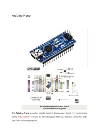
  • 1. Arduino Nano Arduino Nano Development Board Arduino Nano Pin Diagram The Arduino Nano is another popular Arduino development board very much similar to the Arduino UNO. They use the same Processor (Atmega328p) and hence they both can share the same program.
  • 2. Table 1 Pin Category Pin Name Details Power Vin, 3.3V, 5V, GND Vin: Input voltage to Arduino when using an external power source (6-12V). 5V: Regulated power supply used to power microcontroller and other components on the board. 3.3V: 3.3V supply generated by on-board voltage regulator. Maximum current draw is 50mA. GND: Ground pins. Reset Reset Resets the microcontroller. Analog Pins A0 – A7 Used to measure analog voltage in the range of 0-5V Input/Output Pins Digital Pins D0 - D13 Can be used as input or output pins. 0V (low) and 5V (high) Serial Rx, Tx Used to receive and transmit TTL serial data. External Interrupts 2, 3 To trigger an interrupt. PWM 3, 5, 6, 9, 11 Provides 8-bit PWM output. SPI 10 (SS), 11 (MOSI), 12 (MISO) and 13 (SCK) Used for SPI communication.
  • 3. Inbuilt LED 13 To turn on the inbuilt LED. IIC A4 (SDA), A5 (SCA) Used for TWI communication. AREF AREF To provide a reference voltage for input voltage. Arduino Nano Pinout Configuration Arduino Nano Technical Specifications Microcontroller ATmega328P – 8-bit AVR family microcontroller Operating Voltage 5V Recommended Input Voltage for Vin pin 7-12V Analog Input Pins 6 (A0 – A5) Digital I/O Pins 14 (Out of which 6 provide PWM output) DC Current on I/O Pins 40 mA DC Current on 3.3V Pin 50 mA Flash Memory 32 KB (2 KB is used for Bootloader) SRAM 2 KB
  • 4. EEPROM 1 KB Frequency (Clock Speed) 16 MHz Communication IIC, SPI, USART Other Arduino Boards Arduino UNO, Arduino Pro Mini, Arduino Mega, Arduino Due, Arduino MKR1000 Wi- Fi Board, Arduino Leonardo Other Development Boards Raspberry Pi, PIC Development Board, AVR Development Board, MSP430 Launchpad, TEENSY 3.6 Development Board, Intel Edison, ESP32, STM32F103C8T6 - Blue Pill Development Board, NodeMCU ESP8266 Difference between Arduino UNO and Arduino Nano Name Processor Operating/Input Voltage CPU speed Analog In/Out Digital IO/PWM EEPROM / SRAM[kB] Flash USB USART
  • 5. The Arduino Nano is very much similar to the Arduino UNO. They use the same Processor (Atmega328p) and hence they both can share the same program. One big difference between both is the size. UNO is twice as big as Nano and hence occupies more space on your project. Also, Nano is breadboard friendly while Uno is not. To program an Uno, you need a Regular USB cable; whereas for Nano, you will need a mini USB cable. The technical difference between Uno and Nano is shown below: Difference between Arduino Nano and Arduino Mega There is a considerable amount of difference between the Arduino Nano and the Arduino mega as the processor used itself is different. Arduino Mega is more powerful than an Arduino Nano in terms of speed and number of I/O pins. As you might guess, the size is also bigger than an Arduino UNO. Arduino Mega is normally used for projects which require a lot of I/O pins and different communication protocols. The technical difference between Nano and Mega is shown below. Name Processor Operating/Input Voltage CPU speed Analog In/Out Digital IO/PWM EEPROM / SRAM[kB] Flash U Mega ATmega2560 5V / 7-12V 16 MHz 16 / 0 54 / 15 4 / 8 256 R Uno ATmega328P 5V / 7-12V 16 MHz 6 / 0 14 / 6 1 / 2 32 Regular 1 Nano ATmega328P 5V / 7-12V 16 MHz 8 / 0 14 / 6 1 / 2 32 Mini 1
  • 6. Nano ATmega328P 5V / 7-12V 16 MHz 8 / 0 14 / 6 1 / 2 32 M Understanding Arduino Nano The Arduino board is designed in such a way that it is very easy for beginners to get started with microcontrollers. This board especially is breadboard friendly, and that's why it is very easy to handle the connections. Let’s start with powering the Board. Powering you Arduino Nano: There are total three ways by which you can power your Nano. USB Jack: Connect the mini USB jack to a phone charger or computer through a cable and it will draw power required for the board to function Vin Pin: The Vin pin can be supplied with an unregulated 6-12V to power the board. The on-board voltage regulator regulates it to +5V. +5V Pin: If you have a regulated +5V supply then you can directly provide this o the +5V pin of the Arduino. Input/output: There are total 14 digital Pins and 8 Analog pins on your Nano board. The digital pins can be used to interface sensors by using them as input pins or drive loads by using them as output pins. A simple function like pinMode() and digitalWrite() can be used to control their operation. The operating voltage is 0V and 5V for digital pins. The analog pins can measure analog voltage from 0V to 5V using any of the 8 Analog pins using a simple function like analogRead().
  • 7. These pins apart from serving their purpose, can also be used for special purposes, which are discussed below:  Serial Pins 0 (Rx) and 1 (Tx): Rx and Tx pins are used to receive and transmit TTL serial data. They are connected with the corresponding ATmega328P USB to TTL serial chip.  External Interrupt Pins 2 and 3: These pins can be configured to trigger an interrupt on a low value, a rising or falling edge, or a change in value.  PWM Pins 3, 5, 6, 9 and 11: These pins provide an 8-bit PWM output by using analogWrite() function.  SPI Pins 10 (SS), 11 (MOSI), 12 (MISO) and 13 (SCK): These pins are used for SPI communication.  In-built LED Pin 13: This pin is connected with a built-in LED. When pin 13 is HIGH – LED is on and when pin 13 is LOW, it is off.  I2C A4 (SDA) and A5 (SCA): Used for IIC communication using Wire library.  AREF: Used to provide reference voltage for analog inputs with analogReference() function.  Reset Pin: Making this pin LOW, resets the microcontroller. These special functions and their respective pins are illustrated in the Arduino Nano pinout diagram shown above. How to use Arduino Nano It will hardly take 5-10 minutes to upload your first program to Arduino Nano. All you need the Arduino IDE, an USB cable and your Nano board itself. Download and Install Arduino: The first step would be to install the Arduino IDE which is available for download for free from the below link. After installing Arduino, you might also want to install the drivers (link given below) for your Arduino to communicate with your Computer.  Arduino IDE Download  Driver Download
  • 8. Uploading your first program Once arduino IDE is installed on the computer, connect the board with computer using USB cable. Now open the arduino IDE and choose the correct board by selecting Tools>Boards>Arduino/Nano, and choose the correct Port by selecting Tools>Port. Arduino Uno is programmed using Arduino programming language based on Wiring. To get it started with Arduino Uno board and blink the built-in LED, load the example code by selecting Files>Examples>Basics>Blink.Once the example code (also shown below) is loaded into your IDE, click on the ‘upload’ button given on the top bar. Once the upload is finished, you should see the Arduino’s built-in LED blinking. Below is the example code for blinking: // the setup function runs once when you press reset or power the board void setup() { // initialize digital pin LED_BUILTIN as an output. pinMode(LED_BUILTIN, OUTPUT); } // the loop function runs over and over again forever void loop() { digitalWrite(LED_BUILTIN, HIGH); // turn the LED on (HIGH is the voltage level ) delay(1000); // wait for a second digitalWrite(LED_BUILTIN, LOW); // turn the LED off by making the voltage LOW delay(1000); // wait for a second } Applications  Prototyping of Electronics Products and Systems  Multiple DIY Projects.  Easy to use for beginner-level DIYers and makers.  Projects requiring Multiple I/O interfaces and communications.
  • 9. IR Sensor Module IR Sensor/Obstacle Sensor Module IR Sensor Module Pinout IR Sensor Module Pinout Configuration Pin Name Description VCC Power Supply Input GND Power Supply Ground OUT Active High Output
  • 10. IR Sensor Module Features  5VDC Operating voltage  I/O pins are 5V and 3.3V compliant  Range: Up to 20cm  Adjustable Sensing range  Built-in Ambient Light Sensor  20mA supply current  Mounting hole Brief about IR Sensor Module The IR sensor module consists mainly of the IR Transmitter and Receiver, Op-amp, Variable Resistor (Trimmer pot), output LED along with few resistors. IR LED Transmitter IR LED emits light, in the range of Infrared frequency. IR light is invisible to us as its wavelength (700nm – 1mm) is much higher than the visible light range. IR LEDs have light emitting angle of approx. 20-60 degree and range of approx. few centimeters to
  • 11. several feets, it depends upon the type of IR transmitter and the manufacturer. Some transmitters have the range in kilometers. IR LED white or transparent in colour, so it can give out amount of maximum light. Photodiode Receiver Photodiode acts as the IR receiver as its conducts when light falls on it. Photodiode is a semiconductor which has a P-N junction, operated in Reverse Bias, means it start conducting the current in reverse direction when Light falls on it, and the amount of current flow is proportional to the amount of Light. This property makes it useful for IR detection. Photodiode looks like a LED, with a black colour coating on its outer side, Black colour absorbs the highest amount of light. LM358 Opamp LM358 is an Operational Amplifier (Op-Amp) is used as voltage comparator in the IR sensor. the comparator will compare the threshold voltage set using the preset (pin2) and the photodiode’s series resistor voltage (pin3). Photodiode’s series resistor voltage drop > Threshold voltage = Opamp output is High Photodiode’s series resistor voltage drop < Threshold voltage = Opamp output is Low When Opamp's output is high the LED at the Opamp output terminal turns ON (Indicating the detection of Object). Variable Resistor The variable resistor used here is a preset. It is used to calibrate the distance range at which object should be detected. How to Use IR Sensor Module? The 5 VDC supply input is given to the VCC pin and the supply negative is connected to the GND terminal of the module. When no object is detected within the range of the IR receiver, the output LED remains off.
  • 12. When a object is detected within the range of the IR sensor the LED glows. Applications  Obstacle Detection  Industrial safety devices  Wheel encoder 2D-Model
  • 13. MQ-135 - Gas Sensor for Air Quality MQ-135 Gas Sensor/Module MQ-135 Gas Sensor Pinout
  • 14. Pin Configuration: Pin No: Pin Name: Description For Module 1 Vcc Used to power the sensor, Generally the operating voltage is +5V. 2 Ground Used to connect the module to system ground. 3 Digital Out You can also use this sensor to get digital output from this pin, by setting a t value using the potentiometer. 4 Analog Out This pin outputs 0-5V analog voltage based on the intensity of the gas. For Sensor 1 H -Pins Out of the two H pins, one pin is connected to supply and the other to groun 2 A-Pins The A pins and B pins are interchangeable. These pins will be tied to the Supply 3 B-Pins 20. A pins and B pins are interchangeable. One pin will act as output while the ot be pulled to ground. MQ-135 Sensor Features  Wide detecting scope
  • 15.  Fast response and High sensitivity  Stable and long life  Operating Voltage is +5V  Detect/Measure NH3, NOx, alcohol, Benzene, smoke, CO2, etc.  Analog output voltage: 0V to 5V  Digital output voltage: 0V or 5V (TTL Logic)  Preheat duration 20 seconds  Can be used as a Digital or analog sensor  The Sensitivity of Digital pin can be varied using the potentiometer Note: Complete technical information can be found in the MQ-135 Datasheet linked a the bottom of this page. Alternative MQ Gas sensors Sensor Name Gas to measure MQ-2 Methane, Butane, LPG, Smoke MQ-3 Alcohol, Ethanol, Smoke MQ-4 Methane, CNG Gas MQ-5 Natural gas, LPG MQ-6 LPG, butane MQ-7 Carbon Monoxide MQ-8 Hydrogen Gas
  • 16. MQ-9 Carbon Monoxide, flammable gasses MQ131 Ozone MQ135 Air Quality MQ136 Hydrogen Sulphide gas MQ137 Ammonia MQ138 Benzene, Toluene, Alcohol, Propane, Formaldehyde gas, Hydrogen MQ214 Methane, Natural Gas MQ216 Natural gas, Coal Gas MQ303A Alcohol, Ethanol, smoke MQ306A LPG, butane MQ307A Carbon Monoxide MQ309A Carbon Monoxide, flammable gas Selecting between sensor and module When it comes to measuring or detecting a particular Gas, the MQ series Gas sensors are the most inexpensive and commonly used ones. MQ135 is available as a
  • 17. module or as just the sensor alone. If you are trying to only detect (not measuring PPM) the presence of a gas, then you can buy it as a module since it comes with an op-amp comparator and a digital output pin. But if you planning to measure the PPM of a gas it is recommend buying the sensor alone without module. Where to use MQ-135 Gas sensor The MQ-135 Gas sensors are used in air quality control equipments and are suitable for detecting or measuring of NH3, NOx, Alcohol, Benzene, Smoke, CO2. The MQ-135 sensor module comes with a Digital Pin which makes this sensor to operate even without a microcontroller and that comes in handy when you are only trying to detect one particular gas. If you need to measure the gases in PPM, the analog pin need to be used. The analog pin is TTL driven and works on 5V and so can be used with most common microcontrollers. If you are looking for a sensor to detect or measure common air quality gases such as CO2, Smoke, NH3, NOx, Alcohol, Benzene then this sensor might be the right choice for you. How to use MQ-135 Sensors to detect gases You can either use the digital pin or the analog pin to do this. Simplypower the module with 5V and you should notice the power LED on the module to glow and when no gas it detected the output LED will remain turned off meaning the digital output pin will be 0V. Remember that these sensors have to be kept on for pre-heating time (mentioned in features above) before you can actually work with it. Now, introduce the sensor to the gas you want to detect and you should see the output LED to go high along with the digital pin, if not use the potentiometer until the output gets high. Now every time your sensor gets introduced to this gas at this particular concentration the digital pin will go high (5V) else will remain low (0V).
  • 18. You can also use the analog pin to achieve the same thing. Read the analog values (0- 5V) using a microcontroller, this value willbe directly proportional to the concentration of the gas to which the sensor detects. You can experiment with this values and check how the sensor reacts to different concentration of gas and develop your program accordingly. How to use MQ-135 sensor to measure PPM MQ-135 gas sensor applies SnO2 which has a higher resistance in the clear air as a gas-sensing material. When there is an increase in polluting gases, the resistance of the gas sensor decreases along with that. To measure PPM using MQ-135 sensor we need to look into the (Rs/Ro) v/s PPM graph taken from the MQ135 datasheet.
  • 19. The above figure shows shows the typical sensitivity characteristics of the MQ-135 for several gases. in their: Temp: 20, Humidity: 65%, O2 concentration 21%, RL=20kΩ, Ro: sensor resistance at 100ppm of NH3 in the clean air. Rs:sensor resistance at various concentrations of gases. The value of Ro is the value of resistance in fresh air (or the air with we are comparing) and the value of Rs is the value of resistance in Gas concentration. First you should calibrate the sensor by finding the values of Ro in fresh air and then use that value to find Rs using the below formula: Once we calculate Rs and Ro we can find the ratio and then using the graph shown above we can calculate the equivalent value of PPM for that particular gas. Applications:  Used to detect leakage/excess of gases like Ammonia, nitrogen oxide, alcohols, aromatic compounds, sulfide and smoke.  Air quality monitors. 2D model of MQ-135 Gas sensor Use the following MQ135 sensor dimensions to create your own PCB for your application.
  • 20.
  • 21. HC-SR04 Ultrasonic Sensor HC-SR04 Ultrasonic Sensor Module HC-SR04 Ultrasonic Sensor Pinout
  • 22. Ultrasonic Sensor Pinout Configuration Pin Number Pin Name Description 1 Vcc The Vcc pin powers the sensor, typically with +5V 2 Trigger Trigger pin is an Input pin. This pin has to be kept high for 10us to measurement by sending US wave. 3 Echo Echo pin is an Output pin. This pin goes high for a period of time which will to the time taken for the US wave to return back to the sensor. 4 Ground This pin is connected to the Ground of the system. HC-SR04 Sensor Features  Operating voltage: +5V  Theoretical Measuring Distance: 2cm to 450cm  Practical Measuring Distance: 2cm to 80cm  Accuracy: 3mm  Measuring angle covered: <15°  Operating Current: <15mA  Operating Frequency: 40Hz More details can be found in the HC-SR04 ultrasonic sensor datasheet attached at the bottom of this article. Equivalent distance measuring Sensors US transmitter Receiver pair, IR sensor module, IR sensor pair, IR Analog distance sensor,
  • 23. HC-SR04 Ultrasonic Sensor - Working As shown above the HC-SR04 Ultrasonic (US) sensor is a 4 pin module, whose pin names are Vcc, Trigger, Echo and Ground respectively. This sensor is a very popular sensor used in many applications where measuring distance or sensing objects are required. The module has two eyes like projects in the front which forms the Ultrasonic transmitter and Receiver. The sensor works with the simple high school formula that Distance = Speed × Time The Ultrasonic transmitter transmits an ultrasonic wave, this wave travels in air and when it gets objected by any material it gets reflected back toward the sensor this reflected wave is observed by the Ultrasonic receiver module as shown in the picture below Now, to calculate the distance using the above formulae, we should know the Speed and time. Since we are using the Ultrasonic wave we know the universal speed of US wave at room conditions which is 330m/s. The circuitry inbuilt on the module will calculate the time taken for the US wave to come back and turns on the echo pin high for that same particular amount of time, this way we can also know the time taken. Now simply calculate the distance using a microcontroller or microprocessor.
  • 24. How to use the HC-SR04 Ultrasonic Sensor HC-SR04 distance sensor is commonly used with both microcontroller and microprocessor platforms like Arduino, ARM, PIC, Raspberry Pie etc. The following guide is universallysince it has to be followed irrespective of the type of computational device used. Power the Sensor using a regulated +5V through the Vcc ad Ground pins of the sensor. The current consumed by the sensor is less than 15mA and hence can be directly powered by the on board 5V pins (If available). The Trigger and the Echo pins are both I/O pins and hence they can be connected to I/O pins of the microcontroller. To start the measurement, the trigger pin has to be made high for 10uS and then turned off. This action will trigger an ultrasonic wave at frequency of 40Hz from the transmitter and the receiver will wait for the wave to return. Once the wave is returned after it getting reflected by any object the Echo pin goes high for a particular amount of time which will be equal to the time taken for the wave to return back to the sensor. The amount of time during which the Echo pin stays high is measured by the MCU/MPU as it gives the information about the time taken for the wave to return back to the Sensor. Using this information the distance is measured as explained in the above heading. Applications  Used to avoid and detect obstacles with robots like biped robot, obstacle avoider robot, path finding robot etc.  Used to measure the distance within a wide range of 2cm to 400cm  Can be used to map the objects surrounding the sensor by rotating it  Depth of certain places like wells, pits etc can be measured since the waves can penetrate through water 2D model of the component
  • 25.
  • 27. DHT11–Temperature and Humidity Sensor DHT11 Sensor Pinout The DHT11 is a commonly used Temperature and humidity sensor that comes with a dedicated NTC to measure temperature and an 8-bit microcontroller to output the values of temperature and humidity as serial data. DHT11 Pinout Configuration No: Pin Name Description For DHT11 Sensor 1 Vcc Power supply 3.5V to 5.5V 2 Data Outputs both Temperature and Humidity through serial Data 3 NC No Connection and hence not used 4 Ground Connected to the ground of the circuit For DHT11 Sensor module 1 Vcc Power supply 3.5V to 5.5V 2 Data Outputs both Temperature and Humidity through serial Data 3 Ground Connected to the ground of the circuit You can buy DHT11 sensor module from here.
  • 28. DHT11 Specifications  Operating Voltage: 3.5V to 5.5V  Operating current: 0.3mA (measuring) 60uA (standby)  Output: Serial data  Temperature Range: 0°C to 50°C  Humidity Range: 20% to 90%  Resolution: Temperature and Humidity both are 16-bit  Accuracy: ±1°C and ±1% Note: Complete technical details can be found in the DHT11 datasheet linked at the bottom of the page. DHT11 Equivalent Temperature Sensors DHT22, AM2302, SHT71 Other Temperature Sensors: Thermocouple, TMP100, LM75, DS18820, SHT15, LM35DZ, TPA81, D6T Difference between DHT11 Sensor and Module The DHT11 sensor can either be purchased as a sensor or as a module. Either way, the performance of the sensor is same. The sensor will come as a 4-pin package out of which only three pins will be used whereas the module will come with three pins as shown above. The only difference between the sensor and module is that the module will have a filtering capacitor and pull-up resistor inbuilt, and for the sensor, you have to use them externally if required.
  • 29. Where to use DHT11 Sensors The DHT11 is a commonly used Temperature and humidity sensor. The sensor comes with a dedicated NTC to measure temperature and an 8-bit microcontroller to output the values of temperature and humidity as serial data. The sensor is also factory calibrated and hence easy to interface with other microcontrollers. The sensor can measure temperature from 0°C to 50°C and humidity from 20% to 90% with an accuracy of ±1°C and ±1%. So if you are looking to measure in this range then this sensor might be the right choice for you. How to use DHT11 Sensor The DHT11 Sensor is factory calibrated and outputs serial data and hence it is highly easy to set it up. The connection diagram for this sensor is shown below. As you can see the data pin is connected to an I/O pin of the MCU and a 5K pull-up resistor is used. This data pin outputs the value of both temperature and humidity as serial data. If you are trying to interface DHT11 with Arduino then there are ready- made libraries for it which will give you a quick start.
  • 30. If you are trying to interface it with some other MCU, then the datasheet given below will come in handy. The output given out by the data pin will be in the order of 8bit humidity integer data + 8bit the Humidity decimal data +8 bit temperature integer data + 8bit fractional temperature data +8 bit parity bit. To request the DHT11 module to send these data the I/O pin has to be momentarily made low and then held high as shown in the timing diagram below The duration of each host signal is explained in the DHT11 datasheet, with neat steps and illustrative timing diagrams Applications  Measure temperature and humidity  Local Weather station  Automatic climatecontrol  Environment monitoring 2D–model and Dimensions