The document discusses the Arduino board. It contains the following key points:
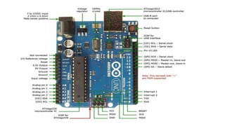
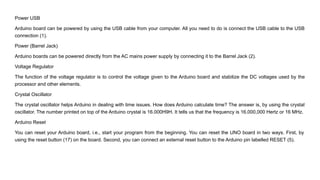
1) The Arduino board can be powered via USB connection to a computer or through an external power supply connected to the barrel jack. It contains a voltage regulator to stabilize the power.
2) It uses a 16MHz crystal oscillator to help with time-keeping. The microcontroller, such as an ATmega328, acts as the brain of the board.
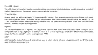
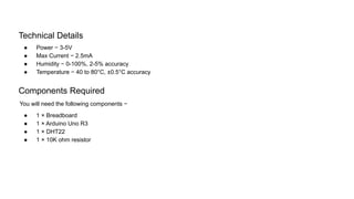
3) It has digital and analog pins that can be configured as inputs or outputs to interface with sensors and actuators. The analog pins can read signals from sensors like temperature and humidity sensors.
3. Power USB
Arduino board can be powered by using the USB cable from your computer. All you need to do is connect the USB cable to the USB
connection (1).
Power (Barrel Jack)
Arduino boards can be powered directly from the AC mains power supply by connecting it to the Barrel Jack (2).
Voltage Regulator
The function of the voltage regulator is to control the voltage given to the Arduino board and stabilize the DC voltages used by the
processor and other elements.
Crystal Oscillator
The crystal oscillator helps Arduino in dealing with time issues. How does Arduino calculate time? The answer is, by using the crystal
oscillator. The number printed on top of the Arduino crystal is 16.000H9H. It tells us that the frequency is 16,000,000 Hertz or 16 MHz.
Arduino Reset
You can reset your Arduino board, i.e., start your program from the beginning. You can reset the UNO board in two ways. First, by
using the reset button (17) on the board. Second, you can connect an external reset button to the Arduino pin labelled RESET (5).
4. Pins (3.3, 5, GND, Vin)
● 3.3V (6) − Supply 3.3 output volt
● 5V (7) − Supply 5 output volt
● Most of the components used with Arduino board works fine with 3.3 volt and 5 volt.
● GND (8)(Ground) − There are several GND pins on the Arduino, any of which can be used to ground your circuit.
● Vin (9) − This pin also can be used to power the Arduino board from an external power source, like AC mains power supply.
Analog pins
The Arduino UNO board has six analog input pins A0 through A5. These pins can read the signal from an analog sensor like the
humidity sensor or temperature sensor and convert it into a digital value that can be read by the microprocessor.
Main microcontroller
Each Arduino board has its own microcontroller (11). You can assume it as the brain of your board. The main IC (integrated
circuit) on the Arduino is slightly different from board to board. The microcontrollers are usually of the ATMEL Company. You must
know what IC your board has before loading up a new program from the Arduino IDE. This information is available on the top of
the IC. For more details about the IC construction and functions, you can refer to the data sheet.
ICSP pin
Mostly, ICSP (12) is an AVR, a tiny programming header for the Arduino consisting of MOSI, MISO, SCK, RESET, VCC, and
GND. It is often referred to as an SPI (Serial Peripheral Interface), which could be considered as an "expansion" of the output.
Actually, you are slaving the output device to the master of the SPI bus.
5. Power LED indicator
This LED should light up when you plug your Arduino into a power source to indicate that your board is powered up correctly. If
this light does not turn on, then there is something wrong with the connection.
TX and RX LEDs
On your board, you will find two labels: TX (transmit) and RX (receive). They appear in two places on the Arduino UNO board.
First, at the digital pins 0 and 1, to indicate the pins responsible for serial communication. Second, the TX and RX led (13). The
TX led flashes with different speed while sending the serial data. The speed of flashing depends on the baud rate used by the
board. RX flashes during the receiving process.
Digital I/O
The Arduino UNO board has 14 digital I/O pins (15) (of which 6 provide PWM (Pulse Width Modulation) output. These pins can be
configured to work as input digital pins to read logic values (0 or 1) or as digital output pins to drive different modules like LEDs,
relays, etc. The pins labeled “~” can be used to generate PWM.
AREF
AREF stands for Analog Reference. It is sometimes, used to set an external reference voltage (between 0 and 5 Volts) as the
upper limit for the analog input pins.
7. Technical Details
● Power − 3-5V
● Max Current − 2.5mA
● Humidity − 0-100%, 2-5% accuracy
● Temperature − 40 to 80°C, ±0.5°C accuracy
Components Required
You will need the following components −
● 1 × Breadboard
● 1 × Arduino Uno R3
● 1 × DHT22
● 1 × 10K ohm resistor
8. Arduino Code
// Example testing sketch for various DHT humidity/temperature sensors
#include "DHT.h"
#define DHTPIN 2 // what digital pin we're connected to
// Uncomment whatever type you're using!
//#define DHTTYPE DHT11 // DHT 11
#define DHTTYPE DHT22 // DHT 22 (AM2302), AM2321
//#define DHTTYPE DHT21 // DHT 21 (AM2301)
// Connect pin 1 (on the left) of the sensor to +5V
// NOTE: If using a board with 3.3V logic like an Arduino Due connect pin 1
// to 3.3V instead of 5V!
// Connect pin 2 of the sensor to whatever your DHTPIN is
// Connect pin 4 (on the right) of the sensor to GROUND
// Connect a 10K resistor from pin 2 (data) to pin 1 (power) of the sensor
// Initialize DHT sensor.
// Note that older versions of this library took an optional third parameter to
// tweak the timings for faster processors. This parameter is no longer needed
// as the current DHT reading algorithm adjusts itself to work on faster procs.
DHT dht(DHTPIN, DHTTYPE);
9. Arduino Code
void setup() {
Serial.begin(9600);
Serial.println("DHTxx test!");
dht.begin();
}
void loop() {
delay(2000); // Wait a few seconds between measurements
float h = dht.readHumidity();
// Reading temperature or humidity takes about 250 milliseconds!
float t = dht.readTemperature();
// Read temperature as Celsius (the default)
float f = dht.readTemperature(true);
// Read temperature as Fahrenheit (isFahrenheit = true)
// Check if any reads failed and exit early (to try again).
if (isnan(h) || isnan(t) || isnan(f)) {
Serial.println("Failed to read from DHT sensor!"
);
return;
}
11. Sensors
● Humidity sensor (DHT22)
● Temperature sensor (LM35)
Humidity Sensor (DHT22)
The DHT-22 (also named as AM2302) is a digital-output, relative humidity, and temperature sensor. It uses a capacitive
humidity sensor and a thermistor to measure the surrounding air, and sends a digital signal on the data pin.