Downloaded 800 times

![Specific gravity =
(C−A)
[(B−A) – (D−C)]](https://image.slidesharecdn.com/bitumenandmodifiedbitumen-161120182627/85/Bitumen-and-modified-bitumen-25-320.jpg)
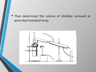
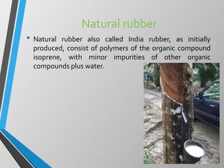
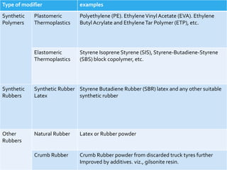
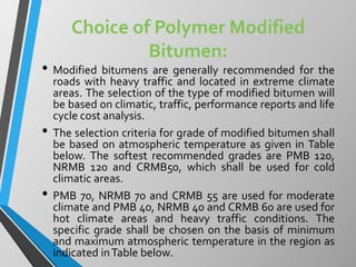
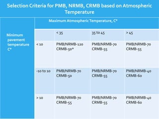
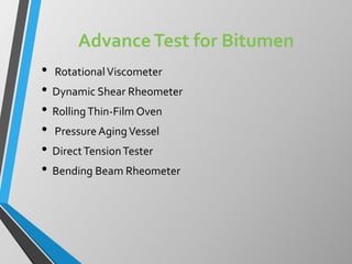


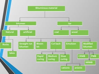
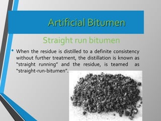
The document provides information on different types of bitumen and bitumen modification. It discusses natural bitumen, artificial bitumen including straight run bitumen and blown bitumen. It also describes cut back bitumen, emulsions, and modified bitumens including crumb rubber modified bitumen, natural rubber modified bitumen, and polymer modified bitumen. The document lists the advantages of modified bitumens and guidelines for their use. It provides details on consistency tests, performance tests, and grades of different modified bitumens.


