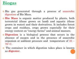
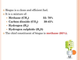
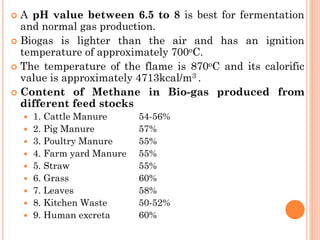
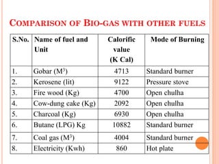
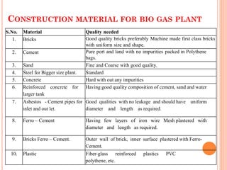
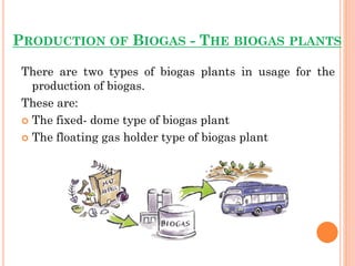
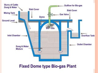
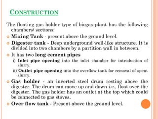
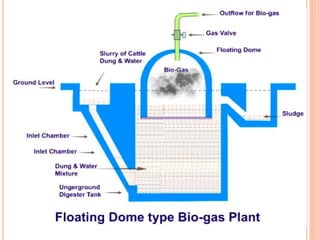
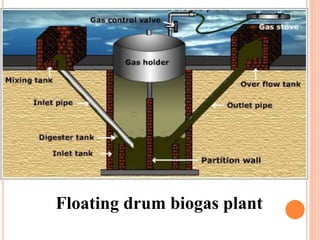
STUDY OF
BIOGAS PLANTS
Dr. Ajay Singh Lodhi
Assistant Professor
College of Agriculture, Balaghat
Jawahar Lal Krishi Vishwa Vidyalaya, Jabalpur (M.P.)
Biogas
 Bio gas generated through a process of anaerobic
digestion of Bio Mass.
 Bio Mass is organic matter produced by plants, both
terrestrial (those grown on land) and aquatic (those
grown in water) and their derivatives. It includes forest
crops and residues, crops grown especially for their
energy content on “energy farms” and animal manure.
 Digestion is a biological process that occurs in the
absence of oxygen and in the presence of anaerobic
organism at ambient pressure and temperature of 35 –
70o C.
 The container in which digestion takes place is known
as digester.
 Biogas is a clean and efficient fuel.
 It is a mixture of:
 Methane (CH4) 55- 70%
 Carbon dioxide (CO2) 30-45%
 Hydrogen (H2)
 Hydrogen sulphide (H2S)
 The chief constituent of biogas is methane (65%).
 A pH value between 6.5 to 8 is best for fermentation
and normal gas production.
 Biogas is lighter than the air and has an ignition
temperature of approximately 700oC.
 The temperature of the flame is 870oC and its calorific
value is approximately 4713kcal/m3 .
 Content of Methane in Bio-gas produced from
different feed stocks
 1. Cattle Manure 54-56%
 2. Pig Manure 57%
 3. Poultry Manure 55%
 4. Farm yard Manure 55%
 5. Straw 55%
 6. Grass 60%
 7. Leaves 58%
 8. Kitchen Waste 50-52%
 9. Human excreta 60%
COMPARISON OF BIO-GAS WITH OTHER FUELS
S.No. Name of fuel and
Unit
Calorific
value
(K Cal)
Mode of Burning
1. Gobar (M3) 4713 Standard burner
2. Kerosene (lit) 9122 Pressure stove
3. Fire wood (Kg) 4700 Open chulha
4. Cow-dung cake (Kg) 2092 Open chulha
5. Charcoal (Kg) 6930 Open chulha
6. Butane (LPG) Kg 10882 Standard burner
7. Coal gas (M3) 4004 Standard burner
8. Electricity (Kwh) 860 Hot plate
SELECTION OF SITE FOR INSTALLATION
OF A BIO GAS PLANT
 The distance between the plant and site of gas
consumption or kitchen should be less to Minimize cost
on gas pipe line and gas leakage.
 It should be near the cattle-shed to minimize the
distance for carrying cattle dung and transportation
cost.
 There should be enough space for storage of digested
slurry or construction of compost pit.
 It is should be 10 to 15 meters away from any drinking
water well to prevent contamination of water.
 The area should be free from roots of trees which are
likely to creep into the digester and cause damage.
 It should be open to receive the Sun’s rays for most part
of the day and to keep the plant in warm. The sunlight
should fall on the plant as temperature between 15oC to
30oC is essential for gas generation at good rate.
 It should be on an elevated area so that the plant does
not get submerged during normal rains.
 Sufficient space must be available for day to day
operation and maintenance. As a guide line 10 to 12 M2
area is needed per M3 of the gas.
 Plenty of water must be available as the Cow dung
slurry with a solid concentration of 7% to 9% is used.
CONSTRUCTION MATERIAL FOR BIO GAS PLANT
S.No. Material Quality needed
1. Bricks Good quality bricks preferably Machine made first class bricks
with uniform size and shape.
2. Cement Pure port and land with no impurities packed in Polythene
bags.
3. Sand Fine and Coarse with good quality.
4. Steel for Bigger size plant. Standard
5. Concrete Hard with out any impurities
6. Reinforced concrete for
larger tank
Having good quality composition of cement, sand and water
7. Asbestos - Cement pipes for
inlet and out let.
Good qualities with no leakage and should have uniform
diameter and length as required.
8. Ferro – Cement Having few layers of iron wire Mesh plastered with
diameter and length as required.
9. Bricks Ferro – Cement. Outer wall of brick, inner surface plastered with Ferro-
Cement.
10. Plastic Fiber-glass reinforced plastics PVC
polythene, etc.
USES OF BIOGAS
 Domestic fuel
 For street lighting
 Generation of electricity
 If compressed, it can replace compressed natural
gas for use in vehicles
PRODUCTION OF BIOGAS - THE BIOGAS PLANTS
There are two types of biogas plants in usage for the
production of biogas.
These are:
 The fixed- dome type of biogas plant
 The floating gas holder type of biogas plant
Fixed dome type
of
Biogas Plant
RAW MATERIALS REQUIRED
 Forms of biomass listed below may be used along with
water.
 Animal dung
 Poultry wastes
 Plant wastes ( Husk, grass, weeds etc.)
 Human excreta
 Industrial wastes(Saw dust, wastes from food processing
industries)
 Domestic wastes (Vegetable peels, waste food materials)
CONSTRUCTION
The biogas plant is a brick and cement structure having
the following five sections:
 Mixing tank present above the ground level.
 Inlet tank: The mixing tank opens underground into a
sloping inlet chamber.
 Digester: The inlet chamber opens from below into the
digester which is a huge tank with a dome like ceiling.
The ceiling of the digester has an outlet with a valve for
the supply of biogas.
 Outlet tank: The digester opens from below into an
outlet chamber.
 Overflow tank: The outlet chamber opens from the top
into a small over flow tank.
WORKING OF FIXED DOME TYPE BIOGAS PLANT
 The various forms of biomass are mixed with an equal
quantity of water in the mixing tank. This forms the
slurry.
 The slurry is fed into the digester through the inlet
chamber.
 When the digester is partially filled with the slurry, the
introduction of slurry is stopped and the plant is left
unused for about two months.
 During these two months, anaerobic bacteria present in
the slurry decomposes or ferments the biomass in the
presence of water.
 As a result of anaerobic fermentation, biogas is formed,
which starts collecting in the dome of the digester.
CONT..
 As more and more biogas starts collecting, the pressure
exerted by the biogas forces the spent slurry into the
outlet chamber.
 From the outlet chamber, the spent slurry overflows
into the overflow tank.
 The spent slurry is manually removed from the overflow
tank and used as manure for plants.
 The gas valve connected to a system of pipelines is
opened when a supply of biogas is required.
 To obtain a continuous supply of biogas, a functioning
plant can be fed continuously with the prepared slurry.
ADVANTAGES OF FIXED DOME TYPE OF
BIOGAS PLANT
 It has low cost compare to floating drum type, as it
uses only cement and no steel.
 It has no corrosion trouble.
 Inexpensive.
 Easy to construct.
 In this type heat insulation is batter as construction
is beneath the ground. Temperature will be constant.
 This type of plant need the service of skilled masons,
who is rather scarce in rural area.
 Gas production per cu m of the digester volume is also
less.
 Scum (floating matter) formation is a problem as no
stirring arrangement.
 It has variable gas pressure.
Disadvantages of fixed dome type of biogas
plant
Floating gas
holder type
of biogas
plant
CONSTRUCTION
The floating gas holder type of biogas plant has the following
chambers/ sections:
 Mixing Tank - present above the ground level.
 Digester tank - Deep underground well-like structure. It is
divided into two chambers by a partition wall in between.
 It has two long cement pipes
i) Inlet pipe opening into the inlet chamber for introduction of
slurry.
ii) Outlet pipe opening into the overflow tank for removal of spent
slurry.
 Gas holder - an inverted steel drum resting above the
digester. The drum can move up and down i.e., float over the
digester. The gas holder has an outlet at the top which could
be connected to gas stoves.
 Over flow tank - Present above the ground level.
Floating drum biogas plant
WORKING
 Slurry (mixture of equal quantities of biomass and
water) is prepared in the mixing tank.
 The prepared slurry is fed into the inlet chamber of the
digester through the inlet pipe.
 The plant is left unused for about two months and
introduction of more slurry is stopped.
 During this period, anaerobic fermentation of biomass
takes place in the presence of water and produces
biogas in the digester.
 Biogas being lighter rises up and starts collecting in
the gas holder. The gas holder now starts moving up.
CONT..
 The gas holder cannot rise up beyond a certain level. As
more and more gas starts collecting, more pressure begins
to be exerted on the slurry.
 The spent slurry is now forced into the outlet chamber from
the top of the inlet chamber.
 When the outlet chamber gets filled with the spent slurry,
the excess is forced out through the outlet pipe into the
overflow tank. This is later used as manure for plants.
 The gas valve of the gas outlet is opened to get a supply of
biogas.
 Once the production of biogas begins, a continuous supply
of gas can be ensured by regular removal of spent slurry
and introduction of fresh slurry.
ADVANTAGES OF FLOATING GAS HOLDER TYPE
BIOGAS PLANT
 It has less scum trouble because solids are constantly
submerged.
 No separate pressure equalizing device needed when
fresh waste is added to the tank or digested slurry is
withdrawn.
 Higher gas production per cu m of digester volume is
achieved.
 Floating drum has welded braces, which help in
breaking the scum by rotation.
 No problem of gas leakage.
 Constant gas pressure.
DISADVANTAGES OF FLOATING GAS HOLDER
TYPE BIOGAS PLANT
 It has higher cost, as cost is dependent on steel and
cement.
 Steel drum may rust, it requires painting once or twice
a year, depending on the humidity of the location.
 Heat is lost through the metal gas holder, hence it
troubles in colder regions and periods.
 Flexible pipe joining the gas holder to the main gas
pipe requires regular maintenance as it is damaged by
ultraviolet rays in the sun. It may twisted also, with
the rotation of the drum for mixing or scum removal.
KVIC BIO GAS PLANT
(KHADI AND VILLAGE INDUSTRIES COMMISSION)
 The design of KVIC plant was developed and
perfected in India in the year 1945. This was taken
up propagation in the villages in the year 1962, by
Khadi and village industries commission, Bombay.
Therefore, it is known as KVIC design.
 The design is available in sizes of 1 cum to 140 cum gas
per day. In KVIC plant the gas is stored in mild steel
drum of storage capacity of 30-40 percent of plant size at a
pressure of about 10cm of water column. Which is
sufficient to carry it up to a length of 20 meters to 100
meters, depending on the size of the plant.
 The Floating gas holder
digester developed in India is
of Masonry construction with
gas holder made of M.S.
Plates. The drum in the KVIC
Model is the costliest
component and its life is
comparatively less.
 The plant consists of two
parts. The digester, which is
well containing the animal
waste in the form of a slurry,
and the dome which floats on
the slurry and serves as the
gas holder.
 The digester is normally below ground level and two pipe
lines lead to its bottom. One for feeding the animal waste
slurry and the other for spent slurry called sludge to come
out after it has under gone fermentation.
 It is worth noting that the sludge to come out retains
all the nitrogen, phosphorous and potassium and in an
excellent fertilizer. A vertical partition wall divides it into
two equal parts and serves to direct the flow of the slurry.
 The gas generation process occurs in two stages. In the first
stage, the complex organic substance contained in the waste
are acted upon by a certain kind of bacteria called acid
formers and are broken up into small chain simple acids. In
the second stage, these acids are acted upon by another kind
of bacteria which produces Methane and Carbon dioxide.
 The calorific value of bio gas ranges from 1600 to 2500
KJ/m3. It is an excellent fuel for cooking and lighting. When
compared with diesel it is also be a very good fuel for
compression, ignition engines and can save 70 to 80 percent
of diesel.
PRAGATHI DESIGN BIO GAS PLANT
 The design has been
developed by United Socio-
Economic Development and
Research Programme
(UNDARP) Pune, in order
to have a cheaper floating
drum bio gas plant. In this
design the depth of pit is less
than K.V.I.C plant so that it
can be constructed in hilly and
high water table areas. The
cost of Pragathi plant is 20%
less than KVIC plant.
 The foundation of this plant is of conical shape, with
difference of one feet between outer periphery and its
center so as to reduce the earth and digester wall work.
It is constructed at the base of the pit with cement, sand
and concrete, keeping the site conditions in view so it
can bear the load due to weight of slurry in the digester.
 The digester of Pragathi design plant start from the
foundation in dome shape thereby reducing the
constructional area, for same digester volume, thus
reducing the cost of construction of the plant. The wall
thickness of digester is kept 75mm only.
 Dome shape construction takes place up to a collar base,
where a central guide frame is provided. The digester
wall above guide-frame is constructed in cylindrical
shape, Partition wall is constructed in the digester for
4cum and bigger sizes so as to control the flow of slurry
inside the digester It divides digester in two parts
separating inlet and outlet.
 The inlet is through pipe, placed while construction
digester wall. It is used for feeding daily slurry in to the
digester and is generally of 100mm diameter. The out
let pipe is also 100mm in diameter, and fixed while
constructing digester wall. The asbestos cement pipe
can be used for inlet and out let.
 The guide frame is made of angle iron and steel pipe, is
embedded in the digester wall at top of spherical
portion of digester. The central guide pipe holds gas
holder which is also made of M.S sheet and angle iron.
It floats up and down along pipe depending on the
quantity of gas in the drum.
JANATA BIO GAS PLANT
 This was first developed by the planning,
Research and Action division, Lucknow, in 1978.
It is an improved version of the Chinese fixed dome bio
gas plant. The foundation of Janata Bio gas plant is laid
at the base of the under ground pit on a leveled ground
bear the load of the slurry as well as digester walls.
 Digester is cylindrical in shape constructed with bricks
and cements, kept the dung slurry for a retention time,
so that the bio gas is produced from the slurry in the
digester. It should be noted that the diameter and
height ratio of the digester is kept 1.75:1.
 The gas is stored in gas
portion which is an
integral part of plant,
between dome and
digester. Where the
usable gas is stored, the
heights of the gas
portion is above the inlet
and outlet openings to
the beginning of dome,
and is equal to
maximum volume of the
gas to be stored (30-40
Percent of plant
Capacity) and equal to
volume of slurry to be
displaced in inlet and
outlet.
 Dome is constructed over the gas portion, with volume
of 60 percent of the plant capacity. It must be
constructed very carefully integrated it with
digester and gas portion so that no leakage of gas
can take place. The gas out let pipe is fixed at the top
of dome for laying the line.
 Inlet and outlet portions are constructed for putting the
fresh slurry in side the plant and to take the digested
slurry out. The inlet and outlet are of larger sizes.
Provided on each side of the digester, facing each other.
The opening to the digester for feeding the waste
material and effluent out let from it are also of large
sizes. The discharge of slurry out of the plant is due to
pressure of the gas in the plant. Over the inlet portion
an inlet Mixing tank is also constructed to mix the dung
and water.
DEENBANDHU BIO GAS PLANT
 This is also a fixed dome plant development by
action for food production, New Delhi, which is a
allow cost bio gas plant. The principle of working of
this plant is same as that of Janata model, except
configuration of inlet entrance and digester.
 The foundation of the plant is constructed in the
segment of spherical shape on the outer periphery of
this foundations the dome shaped digester is
constructed with same base diameter. In this way the
digester, gas portion and dome look as a single unit. The
surface area of biogas plant is reduced with same
digester volume, reducing the earth work and cost of
construction without sacrificing the efficiency.
 The higher compressive strength of the brick masonary
and concreate makes it a safe structure as the plant is
always under compression. A spherical, Structure
loaded from the convex side will be under compression
and therefore, the internal load will not have any
residual effect on the structure.
 At the top of the foundation a window opening is kept
(outlet portion) for the out ward movement of the
digested slurry. The asbestos cement pipe of 15cm
diameter is used for inlet instead of separate opening.
The pipe is embedded in the digester wall at a fixed
position, just opposite to out let opening, to avoid short
circuiting of fresh material and digested slurry.
 The volume of the outlet is increased to produce
requisite gas pressure through the weight of the
displaced slurry. At the top of the dome a gas outlet
pipe is fixed as in case of Janata plant.
ADVANTAGES OF BIOGAS PLANTS
 Reduces burden on forests and fossil fuels
 Produces a clean fuel - helps in controlling air
pollution
 Provides nutrient rich (N & P) manure for plants
 Controls water pollution by decomposing sewage,
animal dung and human excreta.
LIMITATIONS OF BIOGAS PLANTS
 Initial cost of installation of the plant is high.
 Number of cattle owned by an average family of
farmers is inadequate to feed a biogas plant.
CONCLUSION
Biogas is a clean source of energy. Biogas plants have
been in operation for a long period of time, especially
in rural areas around the globe. The research
organizations should focus on newer efficient low cost
designs. The governments can play important role by
introducing different legal frameworks, education
schemes and the availability of technology and
simultaneously creating more awareness and
providing more subsidies.
ADVANTAGES OF BIOGAS AS A FUEL
 High calorific value
 Clean fuel
 No residue produced
 No smoke produced
 Non polluting
 Economical
 Can be supplied through pipe lines
 Burns readily - has a convenient ignition
temperature
APPLICATIONS
The Biogas Train “Amanda”
Sweden
A biogas bus, Sweden
Thank You

Biogas

  • 1.
    STUDY OF BIOGAS PLANTS Dr.Ajay Singh Lodhi Assistant Professor College of Agriculture, Balaghat Jawahar Lal Krishi Vishwa Vidyalaya, Jabalpur (M.P.)
  • 2.
    Biogas  Bio gasgenerated through a process of anaerobic digestion of Bio Mass.  Bio Mass is organic matter produced by plants, both terrestrial (those grown on land) and aquatic (those grown in water) and their derivatives. It includes forest crops and residues, crops grown especially for their energy content on “energy farms” and animal manure.  Digestion is a biological process that occurs in the absence of oxygen and in the presence of anaerobic organism at ambient pressure and temperature of 35 – 70o C.  The container in which digestion takes place is known as digester.
  • 3.
     Biogas isa clean and efficient fuel.  It is a mixture of:  Methane (CH4) 55- 70%  Carbon dioxide (CO2) 30-45%  Hydrogen (H2)  Hydrogen sulphide (H2S)  The chief constituent of biogas is methane (65%).
  • 4.
     A pHvalue between 6.5 to 8 is best for fermentation and normal gas production.  Biogas is lighter than the air and has an ignition temperature of approximately 700oC.  The temperature of the flame is 870oC and its calorific value is approximately 4713kcal/m3 .  Content of Methane in Bio-gas produced from different feed stocks  1. Cattle Manure 54-56%  2. Pig Manure 57%  3. Poultry Manure 55%  4. Farm yard Manure 55%  5. Straw 55%  6. Grass 60%  7. Leaves 58%  8. Kitchen Waste 50-52%  9. Human excreta 60%
  • 5.
    COMPARISON OF BIO-GASWITH OTHER FUELS S.No. Name of fuel and Unit Calorific value (K Cal) Mode of Burning 1. Gobar (M3) 4713 Standard burner 2. Kerosene (lit) 9122 Pressure stove 3. Fire wood (Kg) 4700 Open chulha 4. Cow-dung cake (Kg) 2092 Open chulha 5. Charcoal (Kg) 6930 Open chulha 6. Butane (LPG) Kg 10882 Standard burner 7. Coal gas (M3) 4004 Standard burner 8. Electricity (Kwh) 860 Hot plate
  • 7.
    SELECTION OF SITEFOR INSTALLATION OF A BIO GAS PLANT  The distance between the plant and site of gas consumption or kitchen should be less to Minimize cost on gas pipe line and gas leakage.  It should be near the cattle-shed to minimize the distance for carrying cattle dung and transportation cost.  There should be enough space for storage of digested slurry or construction of compost pit.  It is should be 10 to 15 meters away from any drinking water well to prevent contamination of water.  The area should be free from roots of trees which are likely to creep into the digester and cause damage.
  • 8.
     It shouldbe open to receive the Sun’s rays for most part of the day and to keep the plant in warm. The sunlight should fall on the plant as temperature between 15oC to 30oC is essential for gas generation at good rate.  It should be on an elevated area so that the plant does not get submerged during normal rains.  Sufficient space must be available for day to day operation and maintenance. As a guide line 10 to 12 M2 area is needed per M3 of the gas.  Plenty of water must be available as the Cow dung slurry with a solid concentration of 7% to 9% is used.
  • 9.
    CONSTRUCTION MATERIAL FORBIO GAS PLANT S.No. Material Quality needed 1. Bricks Good quality bricks preferably Machine made first class bricks with uniform size and shape. 2. Cement Pure port and land with no impurities packed in Polythene bags. 3. Sand Fine and Coarse with good quality. 4. Steel for Bigger size plant. Standard 5. Concrete Hard with out any impurities 6. Reinforced concrete for larger tank Having good quality composition of cement, sand and water 7. Asbestos - Cement pipes for inlet and out let. Good qualities with no leakage and should have uniform diameter and length as required. 8. Ferro – Cement Having few layers of iron wire Mesh plastered with diameter and length as required. 9. Bricks Ferro – Cement. Outer wall of brick, inner surface plastered with Ferro- Cement. 10. Plastic Fiber-glass reinforced plastics PVC polythene, etc.
  • 10.
    USES OF BIOGAS Domestic fuel  For street lighting  Generation of electricity  If compressed, it can replace compressed natural gas for use in vehicles
  • 11.
    PRODUCTION OF BIOGAS- THE BIOGAS PLANTS There are two types of biogas plants in usage for the production of biogas. These are:  The fixed- dome type of biogas plant  The floating gas holder type of biogas plant
  • 12.
  • 13.
    RAW MATERIALS REQUIRED Forms of biomass listed below may be used along with water.  Animal dung  Poultry wastes  Plant wastes ( Husk, grass, weeds etc.)  Human excreta  Industrial wastes(Saw dust, wastes from food processing industries)  Domestic wastes (Vegetable peels, waste food materials)
  • 14.
    CONSTRUCTION The biogas plantis a brick and cement structure having the following five sections:  Mixing tank present above the ground level.  Inlet tank: The mixing tank opens underground into a sloping inlet chamber.  Digester: The inlet chamber opens from below into the digester which is a huge tank with a dome like ceiling. The ceiling of the digester has an outlet with a valve for the supply of biogas.  Outlet tank: The digester opens from below into an outlet chamber.  Overflow tank: The outlet chamber opens from the top into a small over flow tank.
  • 15.
    WORKING OF FIXEDDOME TYPE BIOGAS PLANT  The various forms of biomass are mixed with an equal quantity of water in the mixing tank. This forms the slurry.  The slurry is fed into the digester through the inlet chamber.  When the digester is partially filled with the slurry, the introduction of slurry is stopped and the plant is left unused for about two months.  During these two months, anaerobic bacteria present in the slurry decomposes or ferments the biomass in the presence of water.  As a result of anaerobic fermentation, biogas is formed, which starts collecting in the dome of the digester.
  • 16.
    CONT..  As moreand more biogas starts collecting, the pressure exerted by the biogas forces the spent slurry into the outlet chamber.  From the outlet chamber, the spent slurry overflows into the overflow tank.  The spent slurry is manually removed from the overflow tank and used as manure for plants.  The gas valve connected to a system of pipelines is opened when a supply of biogas is required.  To obtain a continuous supply of biogas, a functioning plant can be fed continuously with the prepared slurry.
  • 18.
    ADVANTAGES OF FIXEDDOME TYPE OF BIOGAS PLANT  It has low cost compare to floating drum type, as it uses only cement and no steel.  It has no corrosion trouble.  Inexpensive.  Easy to construct.  In this type heat insulation is batter as construction is beneath the ground. Temperature will be constant.
  • 19.
     This typeof plant need the service of skilled masons, who is rather scarce in rural area.  Gas production per cu m of the digester volume is also less.  Scum (floating matter) formation is a problem as no stirring arrangement.  It has variable gas pressure. Disadvantages of fixed dome type of biogas plant
  • 20.
  • 21.
    CONSTRUCTION The floating gasholder type of biogas plant has the following chambers/ sections:  Mixing Tank - present above the ground level.  Digester tank - Deep underground well-like structure. It is divided into two chambers by a partition wall in between.  It has two long cement pipes i) Inlet pipe opening into the inlet chamber for introduction of slurry. ii) Outlet pipe opening into the overflow tank for removal of spent slurry.  Gas holder - an inverted steel drum resting above the digester. The drum can move up and down i.e., float over the digester. The gas holder has an outlet at the top which could be connected to gas stoves.  Over flow tank - Present above the ground level.
  • 23.
  • 24.
    WORKING  Slurry (mixtureof equal quantities of biomass and water) is prepared in the mixing tank.  The prepared slurry is fed into the inlet chamber of the digester through the inlet pipe.  The plant is left unused for about two months and introduction of more slurry is stopped.  During this period, anaerobic fermentation of biomass takes place in the presence of water and produces biogas in the digester.  Biogas being lighter rises up and starts collecting in the gas holder. The gas holder now starts moving up.
  • 25.
    CONT..  The gasholder cannot rise up beyond a certain level. As more and more gas starts collecting, more pressure begins to be exerted on the slurry.  The spent slurry is now forced into the outlet chamber from the top of the inlet chamber.  When the outlet chamber gets filled with the spent slurry, the excess is forced out through the outlet pipe into the overflow tank. This is later used as manure for plants.  The gas valve of the gas outlet is opened to get a supply of biogas.  Once the production of biogas begins, a continuous supply of gas can be ensured by regular removal of spent slurry and introduction of fresh slurry.
  • 26.
    ADVANTAGES OF FLOATINGGAS HOLDER TYPE BIOGAS PLANT  It has less scum trouble because solids are constantly submerged.  No separate pressure equalizing device needed when fresh waste is added to the tank or digested slurry is withdrawn.  Higher gas production per cu m of digester volume is achieved.  Floating drum has welded braces, which help in breaking the scum by rotation.  No problem of gas leakage.  Constant gas pressure.
  • 27.
    DISADVANTAGES OF FLOATINGGAS HOLDER TYPE BIOGAS PLANT  It has higher cost, as cost is dependent on steel and cement.  Steel drum may rust, it requires painting once or twice a year, depending on the humidity of the location.  Heat is lost through the metal gas holder, hence it troubles in colder regions and periods.  Flexible pipe joining the gas holder to the main gas pipe requires regular maintenance as it is damaged by ultraviolet rays in the sun. It may twisted also, with the rotation of the drum for mixing or scum removal.
  • 28.
    KVIC BIO GASPLANT (KHADI AND VILLAGE INDUSTRIES COMMISSION)  The design of KVIC plant was developed and perfected in India in the year 1945. This was taken up propagation in the villages in the year 1962, by Khadi and village industries commission, Bombay. Therefore, it is known as KVIC design.  The design is available in sizes of 1 cum to 140 cum gas per day. In KVIC plant the gas is stored in mild steel drum of storage capacity of 30-40 percent of plant size at a pressure of about 10cm of water column. Which is sufficient to carry it up to a length of 20 meters to 100 meters, depending on the size of the plant.
  • 29.
     The Floatinggas holder digester developed in India is of Masonry construction with gas holder made of M.S. Plates. The drum in the KVIC Model is the costliest component and its life is comparatively less.  The plant consists of two parts. The digester, which is well containing the animal waste in the form of a slurry, and the dome which floats on the slurry and serves as the gas holder.
  • 30.
     The digesteris normally below ground level and two pipe lines lead to its bottom. One for feeding the animal waste slurry and the other for spent slurry called sludge to come out after it has under gone fermentation.  It is worth noting that the sludge to come out retains all the nitrogen, phosphorous and potassium and in an excellent fertilizer. A vertical partition wall divides it into two equal parts and serves to direct the flow of the slurry.  The gas generation process occurs in two stages. In the first stage, the complex organic substance contained in the waste are acted upon by a certain kind of bacteria called acid formers and are broken up into small chain simple acids. In the second stage, these acids are acted upon by another kind of bacteria which produces Methane and Carbon dioxide.  The calorific value of bio gas ranges from 1600 to 2500 KJ/m3. It is an excellent fuel for cooking and lighting. When compared with diesel it is also be a very good fuel for compression, ignition engines and can save 70 to 80 percent of diesel.
  • 31.
    PRAGATHI DESIGN BIOGAS PLANT  The design has been developed by United Socio- Economic Development and Research Programme (UNDARP) Pune, in order to have a cheaper floating drum bio gas plant. In this design the depth of pit is less than K.V.I.C plant so that it can be constructed in hilly and high water table areas. The cost of Pragathi plant is 20% less than KVIC plant.
  • 32.
     The foundationof this plant is of conical shape, with difference of one feet between outer periphery and its center so as to reduce the earth and digester wall work. It is constructed at the base of the pit with cement, sand and concrete, keeping the site conditions in view so it can bear the load due to weight of slurry in the digester.  The digester of Pragathi design plant start from the foundation in dome shape thereby reducing the constructional area, for same digester volume, thus reducing the cost of construction of the plant. The wall thickness of digester is kept 75mm only.  Dome shape construction takes place up to a collar base, where a central guide frame is provided. The digester wall above guide-frame is constructed in cylindrical shape, Partition wall is constructed in the digester for 4cum and bigger sizes so as to control the flow of slurry inside the digester It divides digester in two parts separating inlet and outlet.
  • 33.
     The inletis through pipe, placed while construction digester wall. It is used for feeding daily slurry in to the digester and is generally of 100mm diameter. The out let pipe is also 100mm in diameter, and fixed while constructing digester wall. The asbestos cement pipe can be used for inlet and out let.  The guide frame is made of angle iron and steel pipe, is embedded in the digester wall at top of spherical portion of digester. The central guide pipe holds gas holder which is also made of M.S sheet and angle iron. It floats up and down along pipe depending on the quantity of gas in the drum.
  • 34.
    JANATA BIO GASPLANT  This was first developed by the planning, Research and Action division, Lucknow, in 1978. It is an improved version of the Chinese fixed dome bio gas plant. The foundation of Janata Bio gas plant is laid at the base of the under ground pit on a leveled ground bear the load of the slurry as well as digester walls.  Digester is cylindrical in shape constructed with bricks and cements, kept the dung slurry for a retention time, so that the bio gas is produced from the slurry in the digester. It should be noted that the diameter and height ratio of the digester is kept 1.75:1.
  • 35.
     The gasis stored in gas portion which is an integral part of plant, between dome and digester. Where the usable gas is stored, the heights of the gas portion is above the inlet and outlet openings to the beginning of dome, and is equal to maximum volume of the gas to be stored (30-40 Percent of plant Capacity) and equal to volume of slurry to be displaced in inlet and outlet.
  • 36.
     Dome isconstructed over the gas portion, with volume of 60 percent of the plant capacity. It must be constructed very carefully integrated it with digester and gas portion so that no leakage of gas can take place. The gas out let pipe is fixed at the top of dome for laying the line.  Inlet and outlet portions are constructed for putting the fresh slurry in side the plant and to take the digested slurry out. The inlet and outlet are of larger sizes. Provided on each side of the digester, facing each other. The opening to the digester for feeding the waste material and effluent out let from it are also of large sizes. The discharge of slurry out of the plant is due to pressure of the gas in the plant. Over the inlet portion an inlet Mixing tank is also constructed to mix the dung and water.
  • 37.
    DEENBANDHU BIO GASPLANT  This is also a fixed dome plant development by action for food production, New Delhi, which is a allow cost bio gas plant. The principle of working of this plant is same as that of Janata model, except configuration of inlet entrance and digester.
  • 38.
     The foundationof the plant is constructed in the segment of spherical shape on the outer periphery of this foundations the dome shaped digester is constructed with same base diameter. In this way the digester, gas portion and dome look as a single unit. The surface area of biogas plant is reduced with same digester volume, reducing the earth work and cost of construction without sacrificing the efficiency.  The higher compressive strength of the brick masonary and concreate makes it a safe structure as the plant is always under compression. A spherical, Structure loaded from the convex side will be under compression and therefore, the internal load will not have any residual effect on the structure.
  • 39.
     At thetop of the foundation a window opening is kept (outlet portion) for the out ward movement of the digested slurry. The asbestos cement pipe of 15cm diameter is used for inlet instead of separate opening. The pipe is embedded in the digester wall at a fixed position, just opposite to out let opening, to avoid short circuiting of fresh material and digested slurry.  The volume of the outlet is increased to produce requisite gas pressure through the weight of the displaced slurry. At the top of the dome a gas outlet pipe is fixed as in case of Janata plant.
  • 40.
    ADVANTAGES OF BIOGASPLANTS  Reduces burden on forests and fossil fuels  Produces a clean fuel - helps in controlling air pollution  Provides nutrient rich (N & P) manure for plants  Controls water pollution by decomposing sewage, animal dung and human excreta.
  • 41.
    LIMITATIONS OF BIOGASPLANTS  Initial cost of installation of the plant is high.  Number of cattle owned by an average family of farmers is inadequate to feed a biogas plant.
  • 42.
    CONCLUSION Biogas is aclean source of energy. Biogas plants have been in operation for a long period of time, especially in rural areas around the globe. The research organizations should focus on newer efficient low cost designs. The governments can play important role by introducing different legal frameworks, education schemes and the availability of technology and simultaneously creating more awareness and providing more subsidies.
  • 43.
    ADVANTAGES OF BIOGASAS A FUEL  High calorific value  Clean fuel  No residue produced  No smoke produced  Non polluting  Economical  Can be supplied through pipe lines  Burns readily - has a convenient ignition temperature
  • 44.
    APPLICATIONS The Biogas Train“Amanda” Sweden A biogas bus, Sweden
  • 45.