SlideShare a Scribd company logo
Instruction Manual &
Experiment Guide
Intelligent
System
Corporation
BIFILAR / TRIFILAR SUSPENSION
APPARATUS
Bifilar / Trifilar Suspension Apparatus
INTELLIGENT SYSTEM CORPORATION
NOTE:
Every effort has been made to ensure that the information contained in this manual is accurate;
however no liability is accepted for errors. Should an error be discovered please inform the
company in writing, giving full details. Any experimental results given are for guidance only and
are not guaranteed as exact answers that can be obtained for a given apparatus; due to the
complex variables applicable to most experiments.
The basic principles set out in the following make no claim to completeness. For further
theoretical explanations, refer to the specialist literature.
The selection of experiments makes no claims of completeness but is intended to be used as a
stimulus for your own experiments.
Bifilar / Trifilar Suspension Apparatus
INTELLIGENT SYSTEM CORPORATION
Table of Contents
Page
1. INTRODUCTION...........................................................................................................1
2. GENERAL DESCRIPTION..........................................................................................2
2.1 Unit Assembly ............................................................................................................2
3. SUMMARY OF THEORY ............................................................................................3
3.1 General........................................................................................................................3
3.2 Performance of experiments .......................................................................................3
4. EXPERIMENT ...............................................................................................................9
Appendix A Experimental Data Sheet
Bifilar / Trifilar Suspension Apparatus
INTELLIGENT SYSTEM CORPORATION 1
1 INTRODUCTION:
The BIFILAR / TRIFILAR SUSPENSION APPARATUS unit consists of frame
made up of Bar, Hollow cylinders, Mounting Plate, Locking wheel and Base plate
Apparatus is capable for determining of mass moments of inertia.
Bifilar / Trifilar Suspension Apparatus
INTELLIGENT SYSTEM CORPORATION 2
2 GENERAL DESCRIPTION:
2.1 Unit Assembly:
Figure: Parts Identification of BIFILAR / TRIFILAR SUSPENSION APPARATUS
1. Bar 2. Cylinder
3. Hollow Cylinder 4. Mounting Plate
5. Locking Wheel 6. Base Plate
Bifilar / Trifilar Suspension Apparatus
INTELLIGENT SYSTEM CORPORATION 3
3 SUMMARY OF THEORY:
3.1 General:
For investigation of pendulums with bifilar or trifilar suspension, a cylinder
(2), a hollow cylinder (3) or a bar (1) can be suspended from the mounting
plate (4) an caused to oscillate. The pendulum length can be altered by
adjusting the thread with the locking wheels (5). The bar is attached to two
threads (bifilar). The cylinder and hollow cylinder have three suspension
points (trifilar). The mounting plate is attached to a base plate (6) for wall
mounting.
Commissioning
• Fix unit to a suitable wall at a height of approx. 1.5 m using the screws and
dowels provided (drill dia. Ø 10 mm) or bolt to the universal frame TM
090 available as an accessory.
• Suspend desired pendulum for threads. The thread length can be set with
clamping screws and should always be the same for the respective bodies.
Important: In the case of wall mounting, ensure sufficient load bearing
capacity of the wall and tighten screws firmly.
If it were to fall, the unit could cause injury and/or be destroyed.
3.2 Performance of Experiment:
Theoretical principles:
3.2.1 Pendulum with bifilar suspension:
The pendulum with bifilar suspension, i.e. suspension from two
threads, corresponds to the ideal mathematical pendulum in the
equation of motion. As the mass only exhibits translatory motion
without rotation, it has the effect of a concentrated mass.
Bifilar / Trifilar Suspension Apparatus
INTELLIGENT SYSTEM CORPORATION 4
Fig. 3.2 Pendulum with bifilar suspension
Solving, this equation of motion permits determination of the period of
oscillation of the pendulum. The pendulum is deflected by the angle φ.
This raises the centre of gravity of the concentrated mass by the
amount h. on releasing the pendulum, the restoring force FR – as a
component of the force due to weight – will attempt to return the
pendulum to its initial position.
Fig. 3.3 Parallelogram of forces of mathematical pendulum
The centre of gravity theorem in x-direction, together with the
acceleration of the centre of gravity x and the restoring force FR = FG
· sin φ = m · g · sin φ, yields
m ·  m · g · sinx ϕ= (3.1)
The angular acceleration is substituted for the acceleration x
,x L x Lϕ ϕ=⋅ =⋅  (3.2)
And the equation expressed in canonical form
sin 0
g
L
ϕ ϕ+ = (3.3)
This non-linear differential equation can be linearized for small
deflections
sin φ = φ , φ < < π
The equation of motion for the mathematical pendulum is thus
0
g
L
ϕ ϕ+ = (3.4)
Bifilar / Trifilar Suspension Apparatus
INTELLIGENT SYSTEM CORPORATION 5
Fig. 3.4 Harmonic Oscillation
The solution is a harmonic oscillation in the form ˆ( ) sin .t tϕ ϕ ω= ,
where ω is the frequency of the oscillation and ˆϕ the initial deflection.
Differentiating twice and inserting this initial approximation into the
equation of motion gives.
2
ˆ ˆsin sin 0
g
t t
L
ϕω ω ϕ ω− + =(3.5)
Resolution for the unknown frequency yields
g
L
ϕ = (3.6)
2
2
L
T
g
π
π
ω
= = (3.7)
This is the natural frequency and period of oscillation or periodic time
of the pendulum. It becomes apparent that the only governing factors
are the length L and the gravitational constant g. The mass and hence
the shape and material of the pendulum have no influence on the
natural frequency and period of oscillation of the system.
Bifilar / Trifilar Suspension Apparatus
INTELLIGENT SYSTEM CORPORATION 6
3.2.2 Pendulum with trifilar suspension:
The pendulum with trifilar suspension is used for experimental
determination of mass moments of inertia. For this purpose the body to
be investigated is subjected to torsional oscillation. The period of
oscillation T can be used to establish the mass moment of inertia J.
When subjected to torsional oscillation, the body executes rotary
movement about its axis of rotation with the angle of rotation α; the
suspension thread moves through the angle φ. In this process the body
is raised by the height h. the force due to weight FG produces a
restoring force FR, which acts on every mass point. The following
applies:
Fig. 3.5 Pendulum with trifilar suspension
L
R
α ϕ= ⋅ (3.8)
FR = FG sin φ = m · g sin φ (3.9)
Where; L = Thread length
R = Radius of rotation
Bifilar / Trifilar Suspension Apparatus
INTELLIGENT SYSTEM CORPORATION 7
Fig. 3.6 Parallelogram of forces
The rotary movement is produced exclusively by the horizontally
acting component FH of the restoring force, to which the following
applies:
The rotary movement is produced exclusively by the horizontally
acting component FH of the restoring force, to which the following
applies:
FH = FR cos φ = m · g cos φ (3.10)
The equilibrium of moments about the axis of rotation can now be set
up.
0HJ F Rα + ⋅ = (3.11)
sin cos 0J m g Rα ϕ ϕ+ ⋅ ⋅ = (3.12)
sin cos 0
L
J m g R
R
ϕ ϕ ϕ⋅ + ⋅ ⋅ = (3.13)
For very small deflections φ << π the equation can be linearised (it is
therefore appropriate to choose the greatest possible thread length L).
the following then applies:
sin φ = φ and cos φ = 1 (3.15)
This yields:
0
L
J m g R
R
ϕ ϕ⋅ + ⋅ ⋅ ⋅ = (3.16)
Bifilar / Trifilar Suspension Apparatus
INTELLIGENT SYSTEM CORPORATION 8
or
2
0
m g R
J L
ϕ ϕ
⋅ ⋅
+ ⋅ =
⋅
 (3.17)
The initial approximation for the differential equation of a harmonic
oscillation (φ (t) = ˆϕ sin ω t, c.f. Section 3.1.1) results in
2
2
ˆ ˆsin sin 0
m g R
t t
J L
ϕω ω ϕ ω
⋅ ⋅
− + =
⋅
(3.18)
Hence the following applies to the natural frequency ω:
2
m g R
J L
ω
⋅ ⋅
=
⋅
(3.19)
or the period of oscillation T:
2
2
2
J L
T
m g R
π
π
ω
⋅
= = ⋅
⋅ ⋅
(3.20)
and the mass moment of inertia J:
2
2
2
4
m g R
J T
Lπ
⋅ ⋅
= ⋅
⋅ ⋅
(3.21)
Bifilar / Trifilar Suspension Apparatus
INTELLIGENT SYSTEM CORPORATION 9
4 Experiment:
The numerical values are specimen experimentation results.
Bifilar suspension with L = 500 mm
The bar is suspended with a thread length of L = 500 mm. This produces a period of
oscillation as per equation (3.7) of
2
2 1.419 ( 9.81 ).
L m
T s where g
g s
π= = =
Table 3.1
Measurement i Time Ti20
1 27.9s
2 28.1s
3 28.1s
Sum ΣTi20 84.1s
Mean valve
20
20
i
i
T
T
i
∑
=
28.033s
20
20
iT
T∗
= 1.4017s
This value is to be checked experimentally. For this purpose, the pendulum is
deflected by a small angle φ and a stopwatch used to measure the time taken for 20
oscillations. This process is repeated three to five times and the mean value calculated
from the readings.
The result is
T*
= 1.4017s
Bifilar / Trifilar Suspension Apparatus
INTELLIGENT SYSTEM CORPORATION 10
Bifilar suspension as second pendulum:

A second pendulum has a period of oscillation of T = 2 s (the point of rest is crossed
once per second). How long must the thread be to maintain this period of oscillation?
Rearranging equation (3.7) for L gives
2
2
0.995
4
T g
L m
π
⋅
= ≈
Table 3.2
Measurement i Time Ti20
1 39.0s
2 38.8s
3 39.0s
Sum ΣTi20 116.8s
Mean valve
20
20
i
i
T
T
i
∑
=
38.933s
20
20
iT
T∗
= 1.947s
As a check, the thread is set to the calculated length and three to five times recorded
for 20 oscillations each.
This result in
T*
= 1.947s
Bifilar / Trifilar Suspension Apparatus
INTELLIGENT SYSTEM CORPORATION 11
Torsional oscillation of a cylinder:
If the cylinder is suspended from three threads, it can exhibit torsional oscillation. If
the mass moment of inertia J of the body is known, the period of oscillation can be
calculated using equation (3.20).
The formula for the mass moment of inertia of a cylinder can be found in literature.
2
2
m
J r= ⋅ (3.22)
Give m = 3 kg and r = 80 mm the result obtained is:
J = 0.0096 kg m2
For R = 65mm and L = 995 mm this yields a theoretical value for the period of
oscillation of
T = 1.74 s
Bifilar / Trifilar Suspension Apparatus
INTELLIGENT SYSTEM CORPORATION 12
Table 3.3
Measurement i Time Ti20
1 35.5s
2 35.0s
3 34.9s
Sum ΣTi20 105.4s
Mean valve
20
20
i
i
T
T
i
∑
=
35.133s
20
20
iT
T∗
= 1.756s
In the experiment, the times required for 20 oscillations with small deflection angles φ
are again measured three to five times. The thread length is set accordingly to 995
mm.
This results in
T*
= 1.756s
Determination of mass moment of inertia of a hollow cylinder:
Use can be made of the trifilar suspension to establish the mass moment of inertia of a
body. In this case the hollow cylinder is to be investigated. The hollow cylinder is a
body easily described in geometrical terms, though the method is also suited to
complex bodies where the mass moment of inertia is difficult to calculate but the mass
is relatively easy to weigh.
Table 3.4
Measurement i Time Ti20
1 40.8s
2 41.2s
3 40.9s
Sum ΣTi20 112.9s
Mean valve
20
20
i
i
T
T
i
∑
=
40.967s
20
20
iT
T∗
= 2.048s
The hollow cylinder is suspended accordingly from three threads. The thread length L
is again 995 mm. the mass of the body is 4kg.
For determination purposes, the times for 20 oscillations are recorded three to five
times. T*
enables the mass moment of inertia to be calculated as per equation (3.21),
with the following result:
Bifilar / Trifilar Suspension Apparatus
INTELLIGENT SYSTEM CORPORATION 13
2
2 2
2
0.0177
4
m g R
J T kg m
Lπ
⋅ ⋅
= ⋅=
⋅ ⋅
The value determined experimentally can be compared to a calculated value. The
formula for the mass moment of inertia of a hollow cylinder is found in literature.
2 2
1 2( )
2
m
J r r= ⋅ + (3.23)
Given m = 4 kg, r1 = 80 mm and r2 = 50 mm the result is:
J = 0.0178 kg m2
Bifilar / Trifilar Suspension Apparatus
INTELLIGENT SYSTEM CORPORATION
APPENDIX A
Experiment Data Sheets
Bifilar / Trifilar Suspension Apparatus
INTELLIGENT SYSTEM CORPORATION
EXPERIMENT
Table 4.1 Bifilar suspension with L = 500 mm
Measurement i Time Ti20
1
2
3
4
5
Sum ΣTi20
Mean valve
20
20
i
i
T
T
i
∑
=
20
20
iT
T∗
=
Table 4.2 Bifilar suspension as second pendulum
Measurement i Time Ti20
1
2
3
4
5
Sum ΣTi20
Mean valve
20
20
i
i
T
T
i
∑
=
20
20
iT
T∗
=
Bifilar / Trifilar Suspension Apparatus
INTELLIGENT SYSTEM CORPORATION
Table 4.3 Torsional oscillation of a cylinder
Measurement i Time Ti20
1
2
3
4
5
Sum ΣTi20
Mean valve
20
20
i
i
T
T
i
∑
=
20
20
iT
T∗
=
Table 4.4 Determination of mass moment of inertia of a hollow cylinder
Measurement i Time Ti20
1
2
3
4
5
Sum ΣTi20
Mean valve
20
20
i
i
T
T
i
∑
=
20
20
iT
T∗
=

More Related Content

What's hot

brakes and dynamometer
brakes and dynamometerbrakes and dynamometer
brakes and dynamometer
Gulfaraz alam
 
Module 4 gear trains
Module 4 gear trainsModule 4 gear trains
Module 4 gear trains
taruian
 
Cams and Followers
Cams and FollowersCams and Followers
Cams and Followers
Yatin Singh
 
Working, Construction And Types of Band Brakes
Working, Construction And Types of Band BrakesWorking, Construction And Types of Band Brakes
Working, Construction And Types of Band Brakes
Khushal Hudke
 
Couple rod of locomotive
Couple rod of locomotiveCouple rod of locomotive
Couple rod of locomotive
mohammed nowfer
 
Inversion of mechanism
Inversion of mechanismInversion of mechanism
Inversion of mechanism
R A Shah
 
Friction clutches brakes and dynamo-meters
Friction clutches brakes and dynamo-metersFriction clutches brakes and dynamo-meters
Friction clutches brakes and dynamo-meters
Dr.Vikas Deulgaonkar
 
Linkage mechanisms - Presentation
Linkage mechanisms - PresentationLinkage mechanisms - Presentation
Linkage mechanisms - Presentation
Lahiru Dilshan
 
Critical speed of shaft
Critical speed of shaftCritical speed of shaft
Critical speed of shaft
Dhruvit Lakhani
 
Inversions of mechanisms
Inversions of mechanismsInversions of mechanisms
Inversions of mechanisms
Chetan Jaganure
 
Quick return mechanism
Quick return mechanismQuick return mechanism
Quick return mechanism
Saif al-din ali
 
Spur gear and design of spur gear
Spur gear and design of spur gearSpur gear and design of spur gear
Spur gear and design of spur gear
Yash Shah
 
UNIT-I_Introduction to Turbomachines.pptx
UNIT-I_Introduction to Turbomachines.pptxUNIT-I_Introduction to Turbomachines.pptx
UNIT-I_Introduction to Turbomachines.pptx
paresh sawai
 
Heat conduction equation
Heat conduction equationHeat conduction equation
Heat conduction equation
Yashawantha K M
 
The four bar chain mechanism
The four bar chain mechanismThe four bar chain mechanism
The four bar chain mechanism
MakwanaMilan1
 
Mechanical drives & power transmission
Mechanical drives & power transmissionMechanical drives & power transmission
Mechanical drives & power transmissionJames Shearer
 
Unit 2.3 Design of Coupling
Unit 2.3 Design of CouplingUnit 2.3 Design of Coupling
Unit 2.3 Design of Coupling
Yugal Kishor Sahu
 
Band brake
Band brake Band brake
Dynamometers
DynamometersDynamometers
Dynamometers
Yash Chauhan
 

What's hot (20)

brakes and dynamometer
brakes and dynamometerbrakes and dynamometer
brakes and dynamometer
 
Module 4 gear trains
Module 4 gear trainsModule 4 gear trains
Module 4 gear trains
 
Cams and Followers
Cams and FollowersCams and Followers
Cams and Followers
 
Working, Construction And Types of Band Brakes
Working, Construction And Types of Band BrakesWorking, Construction And Types of Band Brakes
Working, Construction And Types of Band Brakes
 
Couple rod of locomotive
Couple rod of locomotiveCouple rod of locomotive
Couple rod of locomotive
 
Inversion of mechanism
Inversion of mechanismInversion of mechanism
Inversion of mechanism
 
Friction clutches brakes and dynamo-meters
Friction clutches brakes and dynamo-metersFriction clutches brakes and dynamo-meters
Friction clutches brakes and dynamo-meters
 
Linkage mechanisms - Presentation
Linkage mechanisms - PresentationLinkage mechanisms - Presentation
Linkage mechanisms - Presentation
 
Critical speed of shaft
Critical speed of shaftCritical speed of shaft
Critical speed of shaft
 
Gear train
Gear trainGear train
Gear train
 
Inversions of mechanisms
Inversions of mechanismsInversions of mechanisms
Inversions of mechanisms
 
Quick return mechanism
Quick return mechanismQuick return mechanism
Quick return mechanism
 
Spur gear and design of spur gear
Spur gear and design of spur gearSpur gear and design of spur gear
Spur gear and design of spur gear
 
UNIT-I_Introduction to Turbomachines.pptx
UNIT-I_Introduction to Turbomachines.pptxUNIT-I_Introduction to Turbomachines.pptx
UNIT-I_Introduction to Turbomachines.pptx
 
Heat conduction equation
Heat conduction equationHeat conduction equation
Heat conduction equation
 
The four bar chain mechanism
The four bar chain mechanismThe four bar chain mechanism
The four bar chain mechanism
 
Mechanical drives & power transmission
Mechanical drives & power transmissionMechanical drives & power transmission
Mechanical drives & power transmission
 
Unit 2.3 Design of Coupling
Unit 2.3 Design of CouplingUnit 2.3 Design of Coupling
Unit 2.3 Design of Coupling
 
Band brake
Band brake Band brake
Band brake
 
Dynamometers
DynamometersDynamometers
Dynamometers
 

Similar to Bifilar trifilar suspension apparatus

Design and characterization of a nano-Newton resolution thrust stand - RSI
Design and characterization of a nano-Newton resolution thrust stand - RSIDesign and characterization of a nano-Newton resolution thrust stand - RSI
Design and characterization of a nano-Newton resolution thrust stand - RSIJignesh Soni, PhD
 
Shm 1
Shm 1Shm 1
Shm 1
syar 2604
 
Theory of machines.pdf
Theory of machines.pdfTheory of machines.pdf
Theory of machines.pdf
Ignatius Shiundu
 
vibration lab manual.pdf
vibration lab manual.pdfvibration lab manual.pdf
vibration lab manual.pdf
DEEPAKKUMARD4
 
vibration lab manual 1.doc
vibration lab manual 1.docvibration lab manual 1.doc
vibration lab manual 1.doc
DEEPAKKUMARD4
 
G012414347
G012414347G012414347
G012414347
IOSR Journals
 
ICNR2016_Knuth[1384]
ICNR2016_Knuth[1384]ICNR2016_Knuth[1384]
ICNR2016_Knuth[1384]Ryan McGinty
 
Semester Spring 2020Course Code PHYS218Course Title.docx
Semester Spring 2020Course Code PHYS218Course Title.docxSemester Spring 2020Course Code PHYS218Course Title.docx
Semester Spring 2020Course Code PHYS218Course Title.docx
tcarolyn
 
r5.pdfr6.pdfInertiaOverall.docxDynamics of.docx
r5.pdfr6.pdfInertiaOverall.docxDynamics of.docxr5.pdfr6.pdfInertiaOverall.docxDynamics of.docx
r5.pdfr6.pdfInertiaOverall.docxDynamics of.docx
catheryncouper
 
Belt drives extra
Belt drives extraBelt drives extra
Belt drives extra
Owusu Attakorah MIET
 
2_DOF_Inverted_Pendulum_Laboratory_Session
2_DOF_Inverted_Pendulum_Laboratory_Session2_DOF_Inverted_Pendulum_Laboratory_Session
2_DOF_Inverted_Pendulum_Laboratory_SessionPeixi Gong
 
ES3323 - Project 2 Report - Reverse Engineering a Gear Shaft
ES3323 - Project 2 Report - Reverse Engineering a Gear ShaftES3323 - Project 2 Report - Reverse Engineering a Gear Shaft
ES3323 - Project 2 Report - Reverse Engineering a Gear ShaftConstantine Christelis
 
F4 Experiments
F4 ExperimentsF4 Experiments
F4 Experimentsmarjerin
 
Simple harmonic movement in bandul reversibel
Simple harmonic movement in bandul reversibelSimple harmonic movement in bandul reversibel
Simple harmonic movement in bandul reversibel
umammuhammad27
 
08-Flywheel (2).pdf
08-Flywheel (2).pdf08-Flywheel (2).pdf
08-Flywheel (2).pdf
KgotsoKgengwe
 
18053522.pdf
18053522.pdf18053522.pdf
18053522.pdf
LucasMogaka
 

Similar to Bifilar trifilar suspension apparatus (20)

Design and characterization of a nano-Newton resolution thrust stand - RSI
Design and characterization of a nano-Newton resolution thrust stand - RSIDesign and characterization of a nano-Newton resolution thrust stand - RSI
Design and characterization of a nano-Newton resolution thrust stand - RSI
 
Shm 1
Shm 1Shm 1
Shm 1
 
Theory of machines.pdf
Theory of machines.pdfTheory of machines.pdf
Theory of machines.pdf
 
vibration lab manual.pdf
vibration lab manual.pdfvibration lab manual.pdf
vibration lab manual.pdf
 
vibration lab manual 1.doc
vibration lab manual 1.docvibration lab manual 1.doc
vibration lab manual 1.doc
 
G012414347
G012414347G012414347
G012414347
 
LifeTimeReport_v7
LifeTimeReport_v7LifeTimeReport_v7
LifeTimeReport_v7
 
ICNR2016_Knuth[1384]
ICNR2016_Knuth[1384]ICNR2016_Knuth[1384]
ICNR2016_Knuth[1384]
 
Ballingham_Severance_Lab4
Ballingham_Severance_Lab4Ballingham_Severance_Lab4
Ballingham_Severance_Lab4
 
Vibration lab manual 1
Vibration lab manual 1Vibration lab manual 1
Vibration lab manual 1
 
Semester Spring 2020Course Code PHYS218Course Title.docx
Semester Spring 2020Course Code PHYS218Course Title.docxSemester Spring 2020Course Code PHYS218Course Title.docx
Semester Spring 2020Course Code PHYS218Course Title.docx
 
r5.pdfr6.pdfInertiaOverall.docxDynamics of.docx
r5.pdfr6.pdfInertiaOverall.docxDynamics of.docxr5.pdfr6.pdfInertiaOverall.docxDynamics of.docx
r5.pdfr6.pdfInertiaOverall.docxDynamics of.docx
 
Belt drives extra
Belt drives extraBelt drives extra
Belt drives extra
 
2_DOF_Inverted_Pendulum_Laboratory_Session
2_DOF_Inverted_Pendulum_Laboratory_Session2_DOF_Inverted_Pendulum_Laboratory_Session
2_DOF_Inverted_Pendulum_Laboratory_Session
 
Hooke's law
Hooke's lawHooke's law
Hooke's law
 
ES3323 - Project 2 Report - Reverse Engineering a Gear Shaft
ES3323 - Project 2 Report - Reverse Engineering a Gear ShaftES3323 - Project 2 Report - Reverse Engineering a Gear Shaft
ES3323 - Project 2 Report - Reverse Engineering a Gear Shaft
 
F4 Experiments
F4 ExperimentsF4 Experiments
F4 Experiments
 
Simple harmonic movement in bandul reversibel
Simple harmonic movement in bandul reversibelSimple harmonic movement in bandul reversibel
Simple harmonic movement in bandul reversibel
 
08-Flywheel (2).pdf
08-Flywheel (2).pdf08-Flywheel (2).pdf
08-Flywheel (2).pdf
 
18053522.pdf
18053522.pdf18053522.pdf
18053522.pdf
 

Recently uploaded

The Challenger.pdf DNHS Official Publication
The Challenger.pdf DNHS Official PublicationThe Challenger.pdf DNHS Official Publication
The Challenger.pdf DNHS Official Publication
Delapenabediema
 
Home assignment II on Spectroscopy 2024 Answers.pdf
Home assignment II on Spectroscopy 2024 Answers.pdfHome assignment II on Spectroscopy 2024 Answers.pdf
Home assignment II on Spectroscopy 2024 Answers.pdf
Tamralipta Mahavidyalaya
 
678020731-Sumas-y-Restas-Para-Colorear.pdf
678020731-Sumas-y-Restas-Para-Colorear.pdf678020731-Sumas-y-Restas-Para-Colorear.pdf
678020731-Sumas-y-Restas-Para-Colorear.pdf
CarlosHernanMontoyab2
 
Thesis Statement for students diagnonsed withADHD.ppt
Thesis Statement for students diagnonsed withADHD.pptThesis Statement for students diagnonsed withADHD.ppt
Thesis Statement for students diagnonsed withADHD.ppt
EverAndrsGuerraGuerr
 
Palestine last event orientationfvgnh .pptx
Palestine last event orientationfvgnh .pptxPalestine last event orientationfvgnh .pptx
Palestine last event orientationfvgnh .pptx
RaedMohamed3
 
Language Across the Curriculm LAC B.Ed.
Language Across the  Curriculm LAC B.Ed.Language Across the  Curriculm LAC B.Ed.
Language Across the Curriculm LAC B.Ed.
Atul Kumar Singh
 
Francesca Gottschalk - How can education support child empowerment.pptx
Francesca Gottschalk - How can education support child empowerment.pptxFrancesca Gottschalk - How can education support child empowerment.pptx
Francesca Gottschalk - How can education support child empowerment.pptx
EduSkills OECD
 
Polish students' mobility in the Czech Republic
Polish students' mobility in the Czech RepublicPolish students' mobility in the Czech Republic
Polish students' mobility in the Czech Republic
Anna Sz.
 
TESDA TM1 REVIEWER FOR NATIONAL ASSESSMENT WRITTEN AND ORAL QUESTIONS WITH A...
TESDA TM1 REVIEWER  FOR NATIONAL ASSESSMENT WRITTEN AND ORAL QUESTIONS WITH A...TESDA TM1 REVIEWER  FOR NATIONAL ASSESSMENT WRITTEN AND ORAL QUESTIONS WITH A...
TESDA TM1 REVIEWER FOR NATIONAL ASSESSMENT WRITTEN AND ORAL QUESTIONS WITH A...
EugeneSaldivar
 
The basics of sentences session 5pptx.pptx
The basics of sentences session 5pptx.pptxThe basics of sentences session 5pptx.pptx
The basics of sentences session 5pptx.pptx
heathfieldcps1
 
Synthetic Fiber Construction in lab .pptx
Synthetic Fiber Construction in lab .pptxSynthetic Fiber Construction in lab .pptx
Synthetic Fiber Construction in lab .pptx
Pavel ( NSTU)
 
Instructions for Submissions thorugh G- Classroom.pptx
Instructions for Submissions thorugh G- Classroom.pptxInstructions for Submissions thorugh G- Classroom.pptx
Instructions for Submissions thorugh G- Classroom.pptx
Jheel Barad
 
CLASS 11 CBSE B.St Project AIDS TO TRADE - INSURANCE
CLASS 11 CBSE B.St Project AIDS TO TRADE - INSURANCECLASS 11 CBSE B.St Project AIDS TO TRADE - INSURANCE
CLASS 11 CBSE B.St Project AIDS TO TRADE - INSURANCE
BhavyaRajput3
 
Mule 4.6 & Java 17 Upgrade | MuleSoft Mysore Meetup #46
Mule 4.6 & Java 17 Upgrade | MuleSoft Mysore Meetup #46Mule 4.6 & Java 17 Upgrade | MuleSoft Mysore Meetup #46
Mule 4.6 & Java 17 Upgrade | MuleSoft Mysore Meetup #46
MysoreMuleSoftMeetup
 
The Accursed House by Émile Gaboriau.pptx
The Accursed House by Émile Gaboriau.pptxThe Accursed House by Émile Gaboriau.pptx
The Accursed House by Émile Gaboriau.pptx
DhatriParmar
 
The approach at University of Liverpool.pptx
The approach at University of Liverpool.pptxThe approach at University of Liverpool.pptx
The approach at University of Liverpool.pptx
Jisc
 
"Protectable subject matters, Protection in biotechnology, Protection of othe...
"Protectable subject matters, Protection in biotechnology, Protection of othe..."Protectable subject matters, Protection in biotechnology, Protection of othe...
"Protectable subject matters, Protection in biotechnology, Protection of othe...
SACHIN R KONDAGURI
 
Guidance_and_Counselling.pdf B.Ed. 4th Semester
Guidance_and_Counselling.pdf B.Ed. 4th SemesterGuidance_and_Counselling.pdf B.Ed. 4th Semester
Guidance_and_Counselling.pdf B.Ed. 4th Semester
Atul Kumar Singh
 
Chapter 3 - Islamic Banking Products and Services.pptx
Chapter 3 - Islamic Banking Products and Services.pptxChapter 3 - Islamic Banking Products and Services.pptx
Chapter 3 - Islamic Banking Products and Services.pptx
Mohd Adib Abd Muin, Senior Lecturer at Universiti Utara Malaysia
 
Welcome to TechSoup New Member Orientation and Q&A (May 2024).pdf
Welcome to TechSoup   New Member Orientation and Q&A (May 2024).pdfWelcome to TechSoup   New Member Orientation and Q&A (May 2024).pdf
Welcome to TechSoup New Member Orientation and Q&A (May 2024).pdf
TechSoup
 

Recently uploaded (20)

The Challenger.pdf DNHS Official Publication
The Challenger.pdf DNHS Official PublicationThe Challenger.pdf DNHS Official Publication
The Challenger.pdf DNHS Official Publication
 
Home assignment II on Spectroscopy 2024 Answers.pdf
Home assignment II on Spectroscopy 2024 Answers.pdfHome assignment II on Spectroscopy 2024 Answers.pdf
Home assignment II on Spectroscopy 2024 Answers.pdf
 
678020731-Sumas-y-Restas-Para-Colorear.pdf
678020731-Sumas-y-Restas-Para-Colorear.pdf678020731-Sumas-y-Restas-Para-Colorear.pdf
678020731-Sumas-y-Restas-Para-Colorear.pdf
 
Thesis Statement for students diagnonsed withADHD.ppt
Thesis Statement for students diagnonsed withADHD.pptThesis Statement for students diagnonsed withADHD.ppt
Thesis Statement for students diagnonsed withADHD.ppt
 
Palestine last event orientationfvgnh .pptx
Palestine last event orientationfvgnh .pptxPalestine last event orientationfvgnh .pptx
Palestine last event orientationfvgnh .pptx
 
Language Across the Curriculm LAC B.Ed.
Language Across the  Curriculm LAC B.Ed.Language Across the  Curriculm LAC B.Ed.
Language Across the Curriculm LAC B.Ed.
 
Francesca Gottschalk - How can education support child empowerment.pptx
Francesca Gottschalk - How can education support child empowerment.pptxFrancesca Gottschalk - How can education support child empowerment.pptx
Francesca Gottschalk - How can education support child empowerment.pptx
 
Polish students' mobility in the Czech Republic
Polish students' mobility in the Czech RepublicPolish students' mobility in the Czech Republic
Polish students' mobility in the Czech Republic
 
TESDA TM1 REVIEWER FOR NATIONAL ASSESSMENT WRITTEN AND ORAL QUESTIONS WITH A...
TESDA TM1 REVIEWER  FOR NATIONAL ASSESSMENT WRITTEN AND ORAL QUESTIONS WITH A...TESDA TM1 REVIEWER  FOR NATIONAL ASSESSMENT WRITTEN AND ORAL QUESTIONS WITH A...
TESDA TM1 REVIEWER FOR NATIONAL ASSESSMENT WRITTEN AND ORAL QUESTIONS WITH A...
 
The basics of sentences session 5pptx.pptx
The basics of sentences session 5pptx.pptxThe basics of sentences session 5pptx.pptx
The basics of sentences session 5pptx.pptx
 
Synthetic Fiber Construction in lab .pptx
Synthetic Fiber Construction in lab .pptxSynthetic Fiber Construction in lab .pptx
Synthetic Fiber Construction in lab .pptx
 
Instructions for Submissions thorugh G- Classroom.pptx
Instructions for Submissions thorugh G- Classroom.pptxInstructions for Submissions thorugh G- Classroom.pptx
Instructions for Submissions thorugh G- Classroom.pptx
 
CLASS 11 CBSE B.St Project AIDS TO TRADE - INSURANCE
CLASS 11 CBSE B.St Project AIDS TO TRADE - INSURANCECLASS 11 CBSE B.St Project AIDS TO TRADE - INSURANCE
CLASS 11 CBSE B.St Project AIDS TO TRADE - INSURANCE
 
Mule 4.6 & Java 17 Upgrade | MuleSoft Mysore Meetup #46
Mule 4.6 & Java 17 Upgrade | MuleSoft Mysore Meetup #46Mule 4.6 & Java 17 Upgrade | MuleSoft Mysore Meetup #46
Mule 4.6 & Java 17 Upgrade | MuleSoft Mysore Meetup #46
 
The Accursed House by Émile Gaboriau.pptx
The Accursed House by Émile Gaboriau.pptxThe Accursed House by Émile Gaboriau.pptx
The Accursed House by Émile Gaboriau.pptx
 
The approach at University of Liverpool.pptx
The approach at University of Liverpool.pptxThe approach at University of Liverpool.pptx
The approach at University of Liverpool.pptx
 
"Protectable subject matters, Protection in biotechnology, Protection of othe...
"Protectable subject matters, Protection in biotechnology, Protection of othe..."Protectable subject matters, Protection in biotechnology, Protection of othe...
"Protectable subject matters, Protection in biotechnology, Protection of othe...
 
Guidance_and_Counselling.pdf B.Ed. 4th Semester
Guidance_and_Counselling.pdf B.Ed. 4th SemesterGuidance_and_Counselling.pdf B.Ed. 4th Semester
Guidance_and_Counselling.pdf B.Ed. 4th Semester
 
Chapter 3 - Islamic Banking Products and Services.pptx
Chapter 3 - Islamic Banking Products and Services.pptxChapter 3 - Islamic Banking Products and Services.pptx
Chapter 3 - Islamic Banking Products and Services.pptx
 
Welcome to TechSoup New Member Orientation and Q&A (May 2024).pdf
Welcome to TechSoup   New Member Orientation and Q&A (May 2024).pdfWelcome to TechSoup   New Member Orientation and Q&A (May 2024).pdf
Welcome to TechSoup New Member Orientation and Q&A (May 2024).pdf
 

Bifilar trifilar suspension apparatus

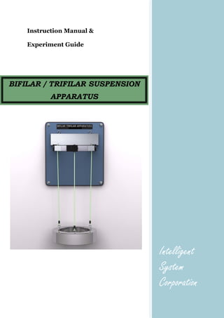
  • 1. Instruction Manual & Experiment Guide Intelligent System Corporation BIFILAR / TRIFILAR SUSPENSION APPARATUS
  • 2. Bifilar / Trifilar Suspension Apparatus INTELLIGENT SYSTEM CORPORATION NOTE: Every effort has been made to ensure that the information contained in this manual is accurate; however no liability is accepted for errors. Should an error be discovered please inform the company in writing, giving full details. Any experimental results given are for guidance only and are not guaranteed as exact answers that can be obtained for a given apparatus; due to the complex variables applicable to most experiments. The basic principles set out in the following make no claim to completeness. For further theoretical explanations, refer to the specialist literature. The selection of experiments makes no claims of completeness but is intended to be used as a stimulus for your own experiments.
  • 3. Bifilar / Trifilar Suspension Apparatus INTELLIGENT SYSTEM CORPORATION Table of Contents Page 1. INTRODUCTION...........................................................................................................1 2. GENERAL DESCRIPTION..........................................................................................2 2.1 Unit Assembly ............................................................................................................2 3. SUMMARY OF THEORY ............................................................................................3 3.1 General........................................................................................................................3 3.2 Performance of experiments .......................................................................................3 4. EXPERIMENT ...............................................................................................................9 Appendix A Experimental Data Sheet
  • 4. Bifilar / Trifilar Suspension Apparatus INTELLIGENT SYSTEM CORPORATION 1 1 INTRODUCTION: The BIFILAR / TRIFILAR SUSPENSION APPARATUS unit consists of frame made up of Bar, Hollow cylinders, Mounting Plate, Locking wheel and Base plate Apparatus is capable for determining of mass moments of inertia.
  • 5. Bifilar / Trifilar Suspension Apparatus INTELLIGENT SYSTEM CORPORATION 2 2 GENERAL DESCRIPTION: 2.1 Unit Assembly: Figure: Parts Identification of BIFILAR / TRIFILAR SUSPENSION APPARATUS 1. Bar 2. Cylinder 3. Hollow Cylinder 4. Mounting Plate 5. Locking Wheel 6. Base Plate
  • 6. Bifilar / Trifilar Suspension Apparatus INTELLIGENT SYSTEM CORPORATION 3 3 SUMMARY OF THEORY: 3.1 General: For investigation of pendulums with bifilar or trifilar suspension, a cylinder (2), a hollow cylinder (3) or a bar (1) can be suspended from the mounting plate (4) an caused to oscillate. The pendulum length can be altered by adjusting the thread with the locking wheels (5). The bar is attached to two threads (bifilar). The cylinder and hollow cylinder have three suspension points (trifilar). The mounting plate is attached to a base plate (6) for wall mounting. Commissioning • Fix unit to a suitable wall at a height of approx. 1.5 m using the screws and dowels provided (drill dia. Ø 10 mm) or bolt to the universal frame TM 090 available as an accessory. • Suspend desired pendulum for threads. The thread length can be set with clamping screws and should always be the same for the respective bodies. Important: In the case of wall mounting, ensure sufficient load bearing capacity of the wall and tighten screws firmly. If it were to fall, the unit could cause injury and/or be destroyed. 3.2 Performance of Experiment: Theoretical principles: 3.2.1 Pendulum with bifilar suspension: The pendulum with bifilar suspension, i.e. suspension from two threads, corresponds to the ideal mathematical pendulum in the equation of motion. As the mass only exhibits translatory motion without rotation, it has the effect of a concentrated mass.
  • 7. Bifilar / Trifilar Suspension Apparatus INTELLIGENT SYSTEM CORPORATION 4 Fig. 3.2 Pendulum with bifilar suspension Solving, this equation of motion permits determination of the period of oscillation of the pendulum. The pendulum is deflected by the angle φ. This raises the centre of gravity of the concentrated mass by the amount h. on releasing the pendulum, the restoring force FR – as a component of the force due to weight – will attempt to return the pendulum to its initial position. Fig. 3.3 Parallelogram of forces of mathematical pendulum The centre of gravity theorem in x-direction, together with the acceleration of the centre of gravity x and the restoring force FR = FG · sin φ = m · g · sin φ, yields m ·  m · g · sinx ϕ= (3.1) The angular acceleration is substituted for the acceleration x ,x L x Lϕ ϕ=⋅ =⋅  (3.2) And the equation expressed in canonical form sin 0 g L ϕ ϕ+ = (3.3) This non-linear differential equation can be linearized for small deflections sin φ = φ , φ < < π The equation of motion for the mathematical pendulum is thus 0 g L ϕ ϕ+ = (3.4)
  • 8. Bifilar / Trifilar Suspension Apparatus INTELLIGENT SYSTEM CORPORATION 5 Fig. 3.4 Harmonic Oscillation The solution is a harmonic oscillation in the form ˆ( ) sin .t tϕ ϕ ω= , where ω is the frequency of the oscillation and ˆϕ the initial deflection. Differentiating twice and inserting this initial approximation into the equation of motion gives. 2 ˆ ˆsin sin 0 g t t L ϕω ω ϕ ω− + =(3.5) Resolution for the unknown frequency yields g L ϕ = (3.6) 2 2 L T g π π ω = = (3.7) This is the natural frequency and period of oscillation or periodic time of the pendulum. It becomes apparent that the only governing factors are the length L and the gravitational constant g. The mass and hence the shape and material of the pendulum have no influence on the natural frequency and period of oscillation of the system.
  • 9. Bifilar / Trifilar Suspension Apparatus INTELLIGENT SYSTEM CORPORATION 6 3.2.2 Pendulum with trifilar suspension: The pendulum with trifilar suspension is used for experimental determination of mass moments of inertia. For this purpose the body to be investigated is subjected to torsional oscillation. The period of oscillation T can be used to establish the mass moment of inertia J. When subjected to torsional oscillation, the body executes rotary movement about its axis of rotation with the angle of rotation α; the suspension thread moves through the angle φ. In this process the body is raised by the height h. the force due to weight FG produces a restoring force FR, which acts on every mass point. The following applies: Fig. 3.5 Pendulum with trifilar suspension L R α ϕ= ⋅ (3.8) FR = FG sin φ = m · g sin φ (3.9) Where; L = Thread length R = Radius of rotation
  • 10. Bifilar / Trifilar Suspension Apparatus INTELLIGENT SYSTEM CORPORATION 7 Fig. 3.6 Parallelogram of forces The rotary movement is produced exclusively by the horizontally acting component FH of the restoring force, to which the following applies: The rotary movement is produced exclusively by the horizontally acting component FH of the restoring force, to which the following applies: FH = FR cos φ = m · g cos φ (3.10) The equilibrium of moments about the axis of rotation can now be set up. 0HJ F Rα + ⋅ = (3.11) sin cos 0J m g Rα ϕ ϕ+ ⋅ ⋅ = (3.12) sin cos 0 L J m g R R ϕ ϕ ϕ⋅ + ⋅ ⋅ = (3.13) For very small deflections φ << π the equation can be linearised (it is therefore appropriate to choose the greatest possible thread length L). the following then applies: sin φ = φ and cos φ = 1 (3.15) This yields: 0 L J m g R R ϕ ϕ⋅ + ⋅ ⋅ ⋅ = (3.16)
  • 11. Bifilar / Trifilar Suspension Apparatus INTELLIGENT SYSTEM CORPORATION 8 or 2 0 m g R J L ϕ ϕ ⋅ ⋅ + ⋅ = ⋅  (3.17) The initial approximation for the differential equation of a harmonic oscillation (φ (t) = ˆϕ sin ω t, c.f. Section 3.1.1) results in 2 2 ˆ ˆsin sin 0 m g R t t J L ϕω ω ϕ ω ⋅ ⋅ − + = ⋅ (3.18) Hence the following applies to the natural frequency ω: 2 m g R J L ω ⋅ ⋅ = ⋅ (3.19) or the period of oscillation T: 2 2 2 J L T m g R π π ω ⋅ = = ⋅ ⋅ ⋅ (3.20) and the mass moment of inertia J: 2 2 2 4 m g R J T Lπ ⋅ ⋅ = ⋅ ⋅ ⋅ (3.21)
  • 12. Bifilar / Trifilar Suspension Apparatus INTELLIGENT SYSTEM CORPORATION 9 4 Experiment: The numerical values are specimen experimentation results. Bifilar suspension with L = 500 mm The bar is suspended with a thread length of L = 500 mm. This produces a period of oscillation as per equation (3.7) of 2 2 1.419 ( 9.81 ). L m T s where g g s π= = = Table 3.1 Measurement i Time Ti20 1 27.9s 2 28.1s 3 28.1s Sum ΣTi20 84.1s Mean valve 20 20 i i T T i ∑ = 28.033s 20 20 iT T∗ = 1.4017s This value is to be checked experimentally. For this purpose, the pendulum is deflected by a small angle φ and a stopwatch used to measure the time taken for 20 oscillations. This process is repeated three to five times and the mean value calculated from the readings. The result is T* = 1.4017s
  • 13. Bifilar / Trifilar Suspension Apparatus INTELLIGENT SYSTEM CORPORATION 10 Bifilar suspension as second pendulum: A second pendulum has a period of oscillation of T = 2 s (the point of rest is crossed once per second). How long must the thread be to maintain this period of oscillation? Rearranging equation (3.7) for L gives 2 2 0.995 4 T g L m π ⋅ = ≈ Table 3.2 Measurement i Time Ti20 1 39.0s 2 38.8s 3 39.0s Sum ΣTi20 116.8s Mean valve 20 20 i i T T i ∑ = 38.933s 20 20 iT T∗ = 1.947s As a check, the thread is set to the calculated length and three to five times recorded for 20 oscillations each. This result in T* = 1.947s
  • 14. Bifilar / Trifilar Suspension Apparatus INTELLIGENT SYSTEM CORPORATION 11 Torsional oscillation of a cylinder: If the cylinder is suspended from three threads, it can exhibit torsional oscillation. If the mass moment of inertia J of the body is known, the period of oscillation can be calculated using equation (3.20). The formula for the mass moment of inertia of a cylinder can be found in literature. 2 2 m J r= ⋅ (3.22) Give m = 3 kg and r = 80 mm the result obtained is: J = 0.0096 kg m2 For R = 65mm and L = 995 mm this yields a theoretical value for the period of oscillation of T = 1.74 s
  • 15. Bifilar / Trifilar Suspension Apparatus INTELLIGENT SYSTEM CORPORATION 12 Table 3.3 Measurement i Time Ti20 1 35.5s 2 35.0s 3 34.9s Sum ΣTi20 105.4s Mean valve 20 20 i i T T i ∑ = 35.133s 20 20 iT T∗ = 1.756s In the experiment, the times required for 20 oscillations with small deflection angles φ are again measured three to five times. The thread length is set accordingly to 995 mm. This results in T* = 1.756s Determination of mass moment of inertia of a hollow cylinder: Use can be made of the trifilar suspension to establish the mass moment of inertia of a body. In this case the hollow cylinder is to be investigated. The hollow cylinder is a body easily described in geometrical terms, though the method is also suited to complex bodies where the mass moment of inertia is difficult to calculate but the mass is relatively easy to weigh. Table 3.4 Measurement i Time Ti20 1 40.8s 2 41.2s 3 40.9s Sum ΣTi20 112.9s Mean valve 20 20 i i T T i ∑ = 40.967s 20 20 iT T∗ = 2.048s The hollow cylinder is suspended accordingly from three threads. The thread length L is again 995 mm. the mass of the body is 4kg. For determination purposes, the times for 20 oscillations are recorded three to five times. T* enables the mass moment of inertia to be calculated as per equation (3.21), with the following result:
  • 16. Bifilar / Trifilar Suspension Apparatus INTELLIGENT SYSTEM CORPORATION 13 2 2 2 2 0.0177 4 m g R J T kg m Lπ ⋅ ⋅ = ⋅= ⋅ ⋅ The value determined experimentally can be compared to a calculated value. The formula for the mass moment of inertia of a hollow cylinder is found in literature. 2 2 1 2( ) 2 m J r r= ⋅ + (3.23) Given m = 4 kg, r1 = 80 mm and r2 = 50 mm the result is: J = 0.0178 kg m2
  • 17. Bifilar / Trifilar Suspension Apparatus INTELLIGENT SYSTEM CORPORATION APPENDIX A Experiment Data Sheets
  • 18. Bifilar / Trifilar Suspension Apparatus INTELLIGENT SYSTEM CORPORATION EXPERIMENT Table 4.1 Bifilar suspension with L = 500 mm Measurement i Time Ti20 1 2 3 4 5 Sum ΣTi20 Mean valve 20 20 i i T T i ∑ = 20 20 iT T∗ = Table 4.2 Bifilar suspension as second pendulum Measurement i Time Ti20 1 2 3 4 5 Sum ΣTi20 Mean valve 20 20 i i T T i ∑ = 20 20 iT T∗ =
  • 19. Bifilar / Trifilar Suspension Apparatus INTELLIGENT SYSTEM CORPORATION Table 4.3 Torsional oscillation of a cylinder Measurement i Time Ti20 1 2 3 4 5 Sum ΣTi20 Mean valve 20 20 i i T T i ∑ = 20 20 iT T∗ = Table 4.4 Determination of mass moment of inertia of a hollow cylinder Measurement i Time Ti20 1 2 3 4 5 Sum ΣTi20 Mean valve 20 20 i i T T i ∑ = 20 20 iT T∗ =