
Recommended
More Related Content
Similar to bhattacharjee2021.pdf
Similar to bhattacharjee2021.pdf (20)
Recently uploaded
Recently uploaded (20)
bhattacharjee2021.pdf
- 1. Core−Shell Nanomaterials for Microwave Absorption and Electromagnetic Interference Shielding: A Review Yudhajit Bhattacharjee and Suryasarathi Bose* Cite This: ACS Appl. Nano Mater. 2021, 4, 949−972 Read Online ACCESS Metrics & More Article Recommendations ABSTRACT: Core−shell nanoparticles are a unique class of nanostructured materials, which received significant attention in the last two decades owing to their exciting properties and a wide variety of applications. By judiciously tuning the “core” as well as the “shell”, an assortment of “core−shell” nanostructures can be obtained with tailorable properties which can play pivotal roles in designing materials for electromagnetic interference (EMI) shielding and microwave absorption. In recent times when the use of high-end electronics has been on the rise, electromagnetic pollution is inevitable and it affects every walk of life. Among numerous e-pollutions, a recently highlighted domain that has far- reaching consequences is electromagnetic interference. EMI is the disturbance created during an electronic device’s operation when it is in the vicinity of an electromagnetic field caused by another electronic or electric device. Since EMI decreases the lifetime and degrades the performance of the electronic instruments and even affects human health, it is crucial to protect sophisticated instruments and components from EM interference. High-performance EMI shields capable of attenuating microwave propagation efficiently have been developed in the past decade. Herein, in this review, we attempted to provide a logical guide to various “core− shell” nanostructures (≤500 nm) that have been synthesized in the past decade for the application in microwave absorption and EMI shielding. The prime focus of this review article is to highlight the fundamental concept of EMI shielding and microwave absorption that have been reported for various systems in the literature along with various synthetic and fabrication strategies in designing suitable broadband EM absorbers/screeners. Finally, we also made an effort to provide a holistic outlook and perspective in which upcoming research will continue to flourish. KEYWORDS: core−shell nanomaterials, EM pollution, electromagnetic interference shielding (EMI), nanocomposites, microwave absorption ■ INTRODUCTION Nanomaterials play a pivotal role in dealing with some of humanity’s important scientific and engineering problems. Their small size, higher surface area, scalability, and several other favorable attributes have made them the most lucrative materials in the 21st century. Nanomaterials can be of various types, categorized mostly due to their shape and properties, which in turn has led to various applications in a wide variety of sectors across the world.1 Among all of the types that exist in the family of nanomaterials, there lies one special kind called “core−shell” nanomaterials, and in this article, we will focus on this special kind. In general, simple or (single-component) nanomaterials are usually composed of only one material; whereas, as the name implies, composite and “core−shell” nanomaterials are composed of two or more materials with a core, which is the inner structure and shell(s) outer layer. Historically (in the late 1980s), scientists observed that heterogeneous, concentric semiconductor nanoparticles provide better efficiency than their corresponding single-particle counterpart and, sometimes, they even develop some new properties.2−4 More recently, during the early 1990s, when researchers synthesized concentric multilayer semiconductor nanoparticles for improv- ing the property of such semiconductor materials, the term core−shell was coined.5,6 With the advancement in this particular field of nanomaterials, the definition of the core− shell nanomaterials can be modified to describe the class of materials that have two components, an inner core and single or multiple outer shells having a distinct boundary separately identifiable. In recent times, there has been a surge in research activity because of the enormous call for an increased number Received: January 28, 2021 Accepted: February 3, 2021 Published: February 11, 2021 Review www.acsanm.org © 2021 American Chemical Society 949 https://dx.doi.org/10.1021/acsanm.1c00278 ACS Appl. Nano Mater. 2021, 4, 949−972 Downloaded via UNIV OF CONNECTICUT on May 16, 2021 at 14:28:48 (UTC). See https://pubs.acs.org/sharingguidelines for options on how to legitimately share published articles.
- 2. of advanced materials fueled by the demands of modern technology. Concurrently, newly developed advanced charac- terization techniques have also significantly helped to elucidate these different core−shell nanostructures’ structures.7,8 Based on the arrangements and compositions of components in the system, core−shell nanomaterials can be categorized into numerous classes which are a combination of inorganic and organic components.7,9 As attention toward target-specific nanostructured materials with multifunctional and/or im- proved properties is increasing, core−shell nanostructures are gradually attracting attention because of their versatile compositions and structures to serve such purposes.10−13 Besides, these nanomaterials have properties which are synergistic among the core and shell and/or exhibit new properties owing to the interactions between the core and the shell.14−18 The design of core−shell nanomaterials can be modified by changing the constituent materials or by altering the thickness ratio core and/or shell. As in the nanosystem, the core and shell may exist in different forms, as shown in Figure 1. Various structural morphologies such as the core may be a solo sphere covered with a continuous shell (Figure 1a) or a continuous multishell (Figure 1b). In some other cases, which is depicted in Figure 1c is the yolk−shell nanostructure where the shell is hollow and in which a small sphere is acting as a core. Extension to this is multishell structures (Figure 1d). In some unusual cases, core−shell structures can form smaller spheres attached (acting as a shell) around the core19 (Figure 1e); in another kind, instead of a continuous layer shell, it takes the form of smaller discrete spheres attached to a core sphere in a discontinuous manner19 (Figure 1f); also, in some situations, the core may not be a single entity but an accumulation of multiple entity/spheres (Figure 1g) within the continuous shell. There are cases where core−shell nanostructures might take the shape of rod, tube, or hexagonal morphologies (Figure 1h,i).20−22 Being a multi-interface in nature, some of the above mention systems have particular advantages and disadvantages. Considering the systems (Figure 1e,f) have a diffused shell structure,19 the surface roughness of these systems will be higher. Due to this, interaction with the polymer matrix will be higher for these particles, and as a result, the mechanical properties of the composite system can be enhanced by carefully tuning the filler concentration.19 Considering the system (Figure 1i) as the aspect ratio of these systems is higher than that of spherical ones, the electrical percolation threshold for these systems will be lower, which will help in enhanced electrical conductivity and EM shielding at a lower concentration.23 For systems like Figure 1a−d, being multi- interface in nature, these systems generate significant interfacial polarization loss and, being periodic in nature, these materials would help in generating multiple scattering/reflections, which helps in effective EM attenuation.24−26 Such distinctive, advantageous, and tailorable structure and properties have also advanced these materials as a significant class of emergent materials for multifarious applications in, for instance, bionanotechnology,27−29 enhanced optical devices,30−32 tail- ored magnetic devices,33,34 bioimaging systems,35,36 energy storage materials,37,38 genetic engineering and stem cells,39,40 solar cells,41,42 and many important catalytic processes.43−46 In the past decade, core−shell nanostructures have emerged as significant yet less explored materials in the field of designing EMI shielding/microwave absorbing materials. The advent of the high-speed data transmission era (4G and 5Gs) and the burgeoning advance in wearable electronic devices not only improved significantly 21st-century modern lifestyle but also brought a great deal of hazardous electromagnetic pollution to human civilization. To counter this, microwave absorbers find their place in various applications, e.g., achieving electromagnetic interference (EMI) shielding,47−51 sophisti- cated contact lenses,52 and improving detector sensitivity.53 In light of the widespread use of numerous optoelectronic devices such as wearable sensors and smartphones and the other Figure 1. Schematic illustration of various core−shell architectures: (a, b) core−shell and core−double shell, (c, d) yolk−shell and yolk−multishell, (e, f) core−diffused shell, (g) multicore−shell, (h) hexagonal core−shell, and (i) rod/tube-like core−shell architectures. ACS Applied Nano Materials www.acsanm.org Review https://dx.doi.org/10.1021/acsanm.1c00278 ACS Appl. Nano Mater. 2021, 4, 949−972 950
- 3. associated complex electromagnetic instruments, EMI shield- ing technology has been becoming even more essential in recent years.26,54−61 An effective EM shielding material not only reduces unwanted EM emissions but also protects electronic components from stray signals. The primary requisite of any EMI shield is to reflect EM radiation using mobile charge carriers which interact explicitly with the incoming fields.62 Therefore, shield materials have to be electrically conductive. However, with the recent progress in the field of microwave absorbing materials, it has been clear that conductivity is not the only criterion. There also follows a secondary mechanism that requires absorption of EM signals due to the material’s magnetic dipoles and/or electric dipole interacting with the EM field. High electrical conductivity is the important variable determining the reflection and absorption traits of the shield materials.63 Furthermore, a third mechanism which in recent days has emerged as the most prevalent mechanism to justify many unusual results is multiple internal reflections. This particular mechanism contributes significantly to EMI shielding effectiveness, though they are still less explored, as this parameter is difficult to quantify with the present-day instrumentation facilities available to us. Multiple internal reflections occur due to the presence of scattering centers, interfaces, or defect sites within the shield.24 In earlier times, metals and metallic architectures were the material of choice to combat EM interference,25 but additional weight and susceptibility to corrosion make metals less preferred in various industries. In modern times with the state of the art electronic equipment and devices, we are in the race for slimmer and slicker devices which are easy to fabricate and possess several other qualities such as being lightweight, flexible, and high-strength. Polymer nanocomposites with embedded conducting, magnetic, or hybrid nanostructures as fillers have become a prevalent substitute for EM shield because of better processability and enhanced scalability.55,64 Recent work in EMI shielding and radio frequency/extremely low-frequency interference screening is in fact shifting toward designing more and more hybrid functional materials which have versatile properties in a single framework. Core−shell nanocomposite materials are one of the lucrative and effective hybrid materials to look for. Herein, in this review article, we aim to focus on various “core−shell” materials that have been designed and utilized as EM screening materials over the past decade along with their mechanistic insights toward shielding. Few other review articles discuss various aspects of EMI shielding materials and offer a comprehensive summary of various domains of EMI shielding such as materials, methods, fabrications, and theories.20,25,64−68 From the existing literature and perspec- tives, we can say that core−shell materials emerge as one of the key aspects of modern-day research in numerous fields7,8 and also in the field of EMI shielding,24 and as far as we are aware, this is the first review article which summarizes various aspects of core−shell materials for designing EMI shielding materials. ■ SCOPE OF THE REVIEW This particular review aims to focus on the progress of the different types of core−shell nanoparticles toward the application toward EMI shielding along with some fundamen- tal concepts and factors related to this domain. We have categorized these types based on the volume of the work done in the past decade toward EMI shielding and adjusted the sequence likewise. These are ones where (i) ferrites act as the core (this includes primitive and non-primitive ferrites), (ii) metal alloys act as the core, (iii) carbonaceous materials act as the core, (iv) metals and metal derivatives act as the core, and finally (v) other relevant systems (this being a miscellaneous section containing different types of systems, viz., polymer, metal carbides, fibers, etc.) act as the core material. We have thoroughly discussed the synthesis of these core−shell materials and discussed their mechanistic insight regarding shielding performance. Finally, we have kept in mind the importance of this class of material and how future research will continue to flourish in this area. ■ FUNDAMENTALS OF EMI SHIELDING The electromagnetic (EM) energy is represented by its two components, static and/or time-varying electric and magnetic force fields, also known as induction fields. These fields are generated in the vicinity of the source and are radiated in directions away from the source. Pertinent to the several modes of field force, the choice of material in each case to shield the relevant field is distinct, since the shielding mechanism involved is different for each of the force fields. The electromagnetic field can be distinguished as two regimes: quasi-static energy (with very low frequency or very large wavelength) stated as near-field and radiated far-field related to high frequency or small wavelength electromagnetic energy.69 About time-varying fields, a wave impedance (intrinsic impedance) parameter (Zw or Z0) can be defined for the medium in terms of the electric (E) and magnetic (H) field intensities. That is, Zw or Z0 = E H Ω. When the source is a capacitive (potential-dependent)-type dipole (as shown in Figure 2), the associated E field is large, which leads to a high wave impedance situation. On the other hand, a current- dependent loop source offers an extensive H field and the corresponding wave impedance of the medium tends to be small.69 The mechanism of shielding is that the shielding medium of appropriate material and geometry, when placed in the region of an electromagnetic field, should offer a barrier impedance ZM sufficiently large in comparison with the wave impedance Zw in the case of an electric field dominant ambient so that the wave is impeded sufficiently and shielded off from entering the region beyond the shielding barrier, as illustrated in Figure 2. Likewise, in the case of the magnetic field caused by a current-dependent loop source, the effective shielding can be achieved by a shield (of appropriate material and geometry) with a barrier admittance YM more than Yw (Figure 3), where Yw = 1/Zw. Figure 2. Schematic illustration of shielding in electric field dominant ambient. ACS Applied Nano Materials www.acsanm.org Review https://dx.doi.org/10.1021/acsanm.1c00278 ACS Appl. Nano Mater. 2021, 4, 949−972 951
- 4. The primary considerations of electromagnetic shielding for time-varying fields are the proper choice of material and the geometry of the shield to provide the necessary barrier- immittance parameter. The material and the geometry cohesively accomplish the shielding by the following mechanisms:65,69 1. Absorption of electromagnetic energy in the shielding medium (absorption loss) 2. Reflection of the electromagnetic energy back into the source side with minimal transmission into the region being shielded (reflection loss) Shielding efficiency is defined as measuring how a material obstructs the electromagnetic radiation/energy of a certain frequency that is incident on it. When EM radiation falls on the shield, then a fraction of incident radiation having power (Pi) is reflected (PR) back, while some fraction of the incident power is absorbed and dissipated in the form of heat energy, and the residual fraction is transmitted (PT) through the shield. Therefore, overall, three distinct processes contribute to the whole attenuation, resulting in total shielding effectiveness = = = = + + P P E E H H SE 10 log 20 log 20 log SE SE SE T i t i t i t R A M (1) In this equation, P, E, and H refer to power, magnetic, and electric field intensities. Thus, SER refers to the total amount of reflection and SEA represents shielding due to absorption. It is advisible to note that contributions from secondary or multiple reflections inside the shield (Figure 4a) only occur in a finite- dimensional system and therefore SEM can be neglected in a thicker medium, allowing the equation to be written as = + SE SE SE T R A (2) Loss in Energy due to Reflection. According to classical theory, reflection is the most important and usually the primary mechanism of shielding. Energy loss due to reflection is mostly attributed to the relative mismatch of impedance between the surface of the shield and the incoming electromagnetic waves. The expression can be written as σ πμ σ μ = = + ∝ Z Z f SE 20 log 4 39.5 10 log 2 ( / ) R 0 in (3) Here σ is the conductivity, frequency is denoted by f, and μ is the relative permeability. It can be inferred from this expression that SER is directly proportional to the conductivity and inversely related to the frequency and relative permeability, and thus, for a constant σ and μ, reflection loss decreases with increasing frequency. For reflection to occur from the material’s surface, the material must have mobile charge carriers (electron and hole). Loss in Energy due to Absorption. Absorption is the secondary mechanism of EM attenuation. According to plane wave theory, the amplitude of the electromagnetic wave reduces exponentially inside the material while passing through it. Thus, loss due to absorption results from ohmic losses and heating of the material owing to the currents induced inside the medium. Absorption loss (SEA) in decibels (dB) for conductive materials is written as πσμ σμ = = ∝ ∝ σ f d ad SE 20 log e 8.7( ) d A / 1/2 (4) here d represents thickness and α signifies the attenuation constant of the shield material. The attenuation constant can be defined as the extent to which the intensity of EM radiation is reduced when it passes through a material, or in other words, it can also be termed as consolidated loss in the system. We can infer from the equation that absorption loss depends on three main factors, viz., conductivity, sample thickness, and permeability of materials. This equation’s applicable condition is that materials have to be conductive; conductive current ≫ displacement current. These dependencies of absorption or reflection loss (SEA/SER) on permeability and conductivity show that, in magneto-conducting materials, shielding is dominated absorption. π λ = a n 4 0 (5) In this equation, λ0 represents the wavelength in a vacuum and n represents the refractive index, which can be written as (εμ)1/2 ; for nonmagnetic materials, μ = 1. Hence, eq 5 can be written as πε λ = a 4 1/2 0 (6) Attenuation due to Multiple-Reflection. When we consider thin samples’ interaction with incoming EM radiation, in those cases, EM waves can be trapped between two boundaries, as waves reflect from the second boundary and return to the first boundary. A part of the wave is absorbed, and the rest is again incident on the secondary boundary. This process occurs back and forth multiple times, as shown in Figure 4, and ultimately, waves lose their power and get trapped inside the material. Figure 3. Schematic illustration of shielding in magnetic field dominant ambient. Figure 4. (a) Schematic Illustration of various mechanisms associated with EM shielding on a 3D material; (b−e) various kinds of multiple internal reflections and in the case of a multilayered structure, a hollow structure, a multishell structure, and in a sphere. ACS Applied Nano Materials www.acsanm.org Review https://dx.doi.org/10.1021/acsanm.1c00278 ACS Appl. Nano Mater. 2021, 4, 949−972 952
- 5. = − δ − SE 20 log(1 e ) d M 2 / (7) Here δ is the skin depth, which is defined as the minimum thickness below which the incident field is attenuated to 1/e of its initial power and is given by δ πσμ = − f ( ) 1/2 (8) As the EM waves are trapped inside the materials, attenuation due to multiple internal reflections is closely related to absorption and depends on the thickness (d) of the materials. Hence, multiple internal reflections play an important role in multilayered, porous structures, multi-interface materials (core−shell), and several others.24,47,59,70 Figure 4 represents multiple reflections inside various systems. In all of these structures, a big surface area and solid structure exclusive of vacant space provide additional active sites for scattering and multiple reflections of EM waves. The porosity and the hollowness of the structure lead to them having a higher surface area, tailorable internal architecture, decreased density, and tunable permeability. All of these properties in turn aid in the improvement in EM shielding performance. ■ FACTORS INFLUENCING EMI SHIELDING Permittivity and Permeability. To design an effective EM shield, two crucial factors, viz., permittivity and permeability, should be taken into account. The EM shielding attribute is correlated with impedance matching (better match leads to absorption and the mismatch leads to reflection), and impedance matching is significantly influenced by the permittivity and permeability of a system according to the following equation71 α π μ ε μ ε μ μ ε ε = ″ ″ − ′ ′ + ″ + ′ ′ + ″ fc 2( ( )( ) 2 2 2 2 (9) As far as the electrical shielding is concerned, conduction loss and polarization loss are two pivotal parameters that account for the dielectric loss. Polarization loss can be attributed to electronic, ionic, dipole orientation, and interfacial polarization (due to trapping of space charge). If we consider free-electron theory, we can write the dielectric loss as ε″ = σ πε f 2 0 , where σ is the electrical conductivity, which signifies that high electrical conductivity, in turn, enhances ε″. Two phenomena, ionic and electronic polarization, occur at the very high-frequency region (above 1000 GHz). Dipole polarization occurs due to the existence of defects and residual groups in the material.72,73 The interfacial polarization and other relaxations occur due to confined space charges at the interfaces. In these situations, the relaxation process can be explored via Cole−Cole plot, and in it, the semicircle plot is obtained due to Debye dipolar relaxation.74 The relationship between ε′ and ε″ can be expressed as ε ε ε ε ε ′ − + ″ = − ∞ ∞ ( ) ( ) ( ) 2 2 s 2 (10) where εs and ε∞ denote the static and relative dielectric permittivity, respectively, at higher frequencies. If polarization relaxation occurs, a semicircle plot is observed while plotting the Cole−Cole plot (ε″ vs ε′). Anisotropy Field. Anisotropy plays an important role in the EM shielding mechanism.75 Magnetic shielding occurs due to several types of magnetic losses, viz., eddy current loss, exchange resonance, and natural ferromagnetic resonance. Natural resonance is related to the materials’ anisotropy field Ha, and the expression is γ π = f H 2 r a (11) Here γ/2π is the gyromagnetic ratio. And Ha can be written as = μ H K M a 2 0 s , where K is the anisotropy constant and Ms is the saturation magnetization.24,76 The above equation reduces to γ μ π = f k M 2 2 r 0 s (12) Thus, it can be inferred from this equation that higher saturation magnetization or a smaller anisotropy field will lead to a decrease in resonance frequency or we can say that a smaller anisotropic field will increase the absorption bandwidth. Eddy Current Loss. Eddy loss is one of the most important losses in the semiconducting as well as conducting magnetic system. Eddy current loss is the Joule loss due to the eddy current induced by the alternating magnetic field. Eddy currents are generated whenever there is a relative motion between a conducting material and a varying external magnetic field exists. Magnetic metals and their alloys (Co, Ni, Fe, FeCo, CoNi, etc.) exhibit very high saturation magnetization and also good magnetic permeability.77,78 The conducting behavior of these materials is primarily responsible for eddy current generation and subsequent loss, resulting in reduced permeability at lower frequencies especially in the megahertz region. Ferrites on the other hand are semiconducting and also exhibit lower saturation magnetization compared to magnetic metals and their alloys, and hence, the resonance frequency of ferrites hovers around the lower GHz frequency range (1−2 GHz).79 This situation limits their usage in the higher GHz region.24 Snoek’s Limit. Another important factor of designing the EM shield is tuning the materials’ permeability and manipulating Snoek’s limit which deals with the microwave permeability spectrum in magnetic materials. Domain wall resonance and spin-exchange resonance are the two different mechanisms that contribute to the complex permeability,80−82 so the permeability is expressed as μ ϖ χ ϖ χ ϖ = + + ( ) 1 ( ) ( ) sr dw (13) where χ ϖ ϖ ϖ = + + K j ( ) 1 ( ) sr sr sr (14) and χ ϖ ϖ ϖ ϖ βϖ = − + K j ( ) dw dw dw 2 dw 2 2 (15) In these equations, ϖ represents the radio frequency magnetic field, ϖsr is the spin resonance, and ϖdw denotes the domain wall motion frequency. Ksr and Kdw denote the static spin and domain wall motion susceptibilities, and β denotes the domain wall damping factor. It has been observed that, although the spin rotation factor remains in the higher frequency, the domain wall contribution diminishes. Therefore, above 100 MHz, complex permeability is the factor that is governed only by the spin rotational component. In terms of magnetization, the relation between Ksr and ϖsr can be written as ACS Applied Nano Materials www.acsanm.org Review https://dx.doi.org/10.1021/acsanm.1c00278 ACS Appl. Nano Mater. 2021, 4, 949−972 953
- 6. π = K M K 2 sr s 2 1 (16) and ϖ γ = ′ C K M 2 sr 1 s (17) Here saturation magnetization is denoted by Ms and K1 is the magnetocrystalline anisotropy, and γ is the gyro-magnetic ratio. ϖ πγ = ′ K C M 2 sr sr s (18) At resonance frequency ϖsr = ϖr = 2πfr ϖ μ − ∝ M ( 1) r s (19) This eq 19 is referred to as Snoek’s limit, which provides an understanding of how to achieve control on permeability in the case of ferrite. Morphology and Size and Interfaces. Morphology and particle size play a huge role in EMI shielding.75 The dimensions of magnetic materials significantly influence their permeability, as has been discussed in earlier sections. In anisotropic materials, alteration in anisotropy energy can alter the spin relaxation time.75,83 Apart from the bulk magnets, permeability in nanomaterials is controlled by relaxation mechanisms. The alteration in anisotropy energy alters the spin relaxation time. Spin fluctuation remains very fast in the superparamagnetic state owing to its small size; hence, relaxation occurs at higher frequencies.84−87 Biswas et al. reported the effect of shape anisotropy and size on the EMI shielding properties in a polycarbonate (PC)/polyvinylidene difluoride (PVDF) blend.83 Moreover, certain morphologies that generate high porosity and larger surface area introduce multiple interfaces that accrue bound charges at the interfaces, causing the polarization effect known as Maxwell−Wagner polarization.88 Arief et al. reported various nanoengineered FeCo anisometric nanostructures in a poly(vinylidene difluoride) matrix for EMI shielding where various morphol- ogies and their effect were studied.83 Furthermore, several surfaces hold unsaturated bonds that are primarily accountable for dipolar polarization, and therefore, we can conclude that multi-interface materials are advantageous for EM attenu- ation.25 Bhattacharjee et al. studied the multi-interface nature in a composite system and concluded that multiple interfaces in a single system could synergistically help in effective EMI shielding.24 Heat Treatment and Time. The classical understanding of materials science tells us that heat treatment (annealing) increases disorder and subsequently creates defects in vacancies, substitution in the system, and generating dangling bonds. These are observed in many ferrite systems where reflection loss is altered by altering the annealing temper- ature.89 These defects and other associated phenomena create an additional energy level around the Fermi level, leading to a significant change in attenuation. In some cases, reaction conditions such as reaction time and temperature also influence reflection loss,89 as altering reaction conditions will lead to changes in structural features of the system as time and temperature are altered. Iqbal et al. reported the thermal annealing driven exceptional shielding performance of the Ti3CNTx (Mxene) system. They have achieved significant enhancement in EMI shielding when annealing was done at 350 °C in a 40 μm Mxene film.59 Wu et al. also studied the effect of annealing temperature on microwave attenuation for reduced graphene oxide. They have found that, with the increase in the annealing temperature, oxygen functional groups can be effectively removed from graphene oxide (GO), especially the groups which are on the surface. The ratio of oxygen functional groups has a direct effect on the EA and EMI shielding performance of reduced graphene oxide.90 Sharma et al. studied the mechanism of growth for a hybrid structure comprised of reduced graphene oxide (rGO) and CuS microflowers as a function of time and investigated its influence on EMI shielding performace.91 Thickness. Other than the specific significance of skin depth over EMI shielding, thickness, in general, influences the EM shielding performance. According to the quarter wave- length theory, minimum reflection loss (RLmin) of the incident microwave occurs when the thickness of the absorber is approximately a quarter of the propagating wavelength and multiplied by an odd number and this can be expressed as92 λ = t n 4 m m (20) where n is any positive integer number (1, 2, 3, ...) so that n = 1 corresponds to the first dip at low frequency. The transmitting wavelength inside the material (λm) is given by λ λ μϵ = [ ] m 0 1/2 (21) The matching condition resulting in the exclusion of the incident and reflected waves at the surface of the absorber material, for example, the dips at t = 5 mm, occurred at (λm/4), (3λm/4), and so on. Therefore, from this, we can conclude that, with the increasing sample thickness, reflection peaks shift toward the lower frequencies. ■ EM ABSORPTION IN COMPOSITES Having discussed how magnetic and nonmagnetic materials shield EM waves and the factors that are responsible for that, we shall discuss composite systems in this section, that have certain differences with respect to the previous scenario. In the composite materials, heterogeneous micro/nanostructures exhibit variation in the material’s local field, which works as a polarization site.77,93 These polarization centers generate lag in the displacement current relative to the conduction current. In the nanocomposite, matrix and filler both play a very important role in significantly influencing EM shielding behavior. The composite matrix and filler both have different electromagnetic properties, and in this condition, permittivity and permeability can be treated as a complex entity and substituted by effective permittivity (ε = ε′ + iε″) and permeability (μ = μ″ + jμ″), where i is the imaginary number and ε is a complex entity. Here, ε′ denotes the electrical component’s energy storage capacity and ε″ is the dielectric loss. On the other hand, μ′ and μ″ denote the magnetic energy storage and various magnetic losses. These parameters (complex permeability) possess a complex dependency on the morphology, size, and conductivity which we discussed earlier. As far as the application of composite is concerned, in fields such as radar and stealth, the essential prerequisite is to modulate (decrease the effective permittivity and increase the effective permeability) the effective μ and ε in such a way so that we can minimize the reflection amount and enhance the absorption. This can be achieved by minimizing the impedance ACS Applied Nano Materials www.acsanm.org Review https://dx.doi.org/10.1021/acsanm.1c00278 ACS Appl. Nano Mater. 2021, 4, 949−972 954
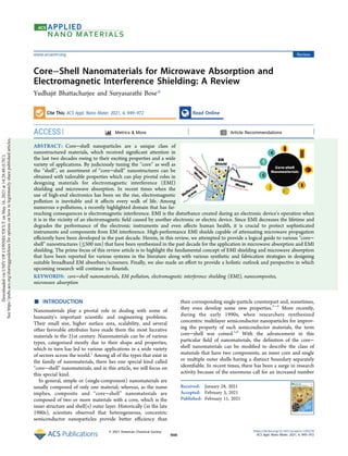
- 7. mismatch among shielding materials and free space. According to transmission line theory, intrinsic surface impedance can be written as65 πμ σ πε = | | | | = + Z E H fj fj 2 2 in (22) and reflection loss can be written as70 = − + z z z z RL (dB) 20 log in 0 in 0 (23) The maximum absorption of EM waves implies minimum reflection loss (RLmin), and this happens when the impedance of free space and composite material is matched. Impedance matching conditions in the ideal situation is when Zin = Z0 = 377 Ω.20 Here impedance of air is denoted by Z0, and Zin represents the input impedance of the composite (absorber material). The above condition is satisfied at a definite matching thickness (tm) and the corresponding matching frequency (fm). An effective EM absorber is supposed to make the absorption bandwidth as broad as possible, which is controlled by the quarter-wavelength theory discussed earlier and given by the equation92 εμ = t nc f 4 m m (24) Here n is the refractive index and c the speed of light. ■ DISCUSSION OF EMI SHIELDING/MICROWAVE ABSORPTION OF VARIOUS CORE−SHELL MATERIALS 1. Ferrites as a Core. 1.a. Primitive Ferrite (Fe3O4/Fe2O3) as a Core. Iron oxide nanoparticles are one of the primitive classes of magnetic nanomaterials which existed in the literature. In the last two decades, various synthetic strategies of its multidimensional shapes and sizes came into prominence because of their multifarious applications.94 This system (Fe3O4/Fe2O3) under an alternating magnetic field (AMF) can generate heat which makes magnetic iron oxide nano- particles an ideal heat source for biomedical applications including cancer thermoablative therapy, tissue preservation, and remote control of cell function.95−100 In various cases, this particular system has been used as a nanofluid coolant for modern engines.101 Due to the presence of magnetic dipoles in the system, it generates a substantial amount of magnetic heating when interacted with the external EM field.75,102 This particular trait makes these systems lucrative for designing EM screeners.24,75 In the following section, we will discuss about various systems where these primitive ferrites act as a "core" structure. 1.a.i. Carbon/Polymer as a Shell. Chen et al. reported a facile three-step synthesis (hydrothermal followed by annealing at 360 °C) strategy to make porous Fe3O4@C core−shell nanorods having ferromagnetic characteristics at room temper- ature. Here glucose was chosen as a source of carbon, which acts as a shell. In this system, effective complementarities among the dielectric loss that originates from carbon shells and the magnetic loss that originates from the magnetic core enable Figure 5. (a) Schematic illustration of the synthesis scheme of Fe3O4@C. (b) Electron micrograph of nanomaterials.104 (c) Reflection loss profile of the composite. Reproduced with permission from ref 104. Copyright 2020 Elsevier. ACS Applied Nano Materials www.acsanm.org Review https://dx.doi.org/10.1021/acsanm.1c00278 ACS Appl. Nano Mater. 2021, 4, 949−972 955
- 8. the porous core−shell nanorods to screen an electromagnetic wave frequency region over 2−18 GHz. They achieved a maximum reflection loss of 27.9 dB at 14.96 GHz for the composite made with wax (55 wt % filler) with a thickness of 2 mm.103 Meng et al. reported a 3D foam using an Fe3O4@C core−shell structure. They used resorcinol as a carbon source in this work. Synthesis is done by in situ polymerization and subsequent carbothermal reduction in a tube furnace, where Fe2O3 was converted to Fe3O4, and the final foam-like structure was obtained as illustrated in Figure 5a,b. Here they have adjusted the amount of polymeric precursor to perfectly control the outer carbon layer with an average thickness range of 9.1−34.8 nm. Due to the synergistic contribution of the core and shell, it helps in impedance matching, which in turns produces a minimum RL value of −55.5 dB with a 2.5 mm absorber thickness and 28.3 nm shell thickness. Especially, on reduction of the thickness from 5.5 to 1.4 mm, the Fe3O4@C exhibits efficient absorption (RL ≤ −20 dB) in an ultrawide band (14.9 GHz), as illustrated in Figure 5c.104 Magnetic vortex core−shell (Fe3O4@C) nanorings were synthesized by Wang et al. and composited with wax to make a composite which showed a significant reflection loss of 61.54 dB, for 1.5 mm thickness. The outstanding attenuation was mainly due to the eddy loss enhanced by a combination of confinement vortex and strain-driven vortex.105 For the Fe3O4@PANI system, Bhattacharjee et al. reported a PVDF-based flexible composite of it for EMI shielding application. In this work, the author reported a core−shell system with a core of 400 nm diameter and a PANI shell thickness of 20−25 nm. Along with 3 wt % of carbon nanotube and 10 wt % of core−shell filler materials when added to the PVDF matrix, this composite showed superior performance of total shielding effectiveness of 19.5 dB at a thickness of only 300 μm.24 Manna et al. reported a trilaminar (core−shell) nanostructure comprised of Fe3O4@C@PANI. For ease of understanding, this ternary composite was synthesized by varying the anile and Fe3O4@C content, as illustrated in Figure 6a. They have reported a significantly high value of EMI shielding, and it could be attributed to the presence of dual interfaces and dielectric−magnetic integration Fe3O4@C@ PANI. The authors mentioned that higher dielectric loss through interfacial polarization and spin relaxation in Fe3O4@ C@PANI could also contribute toward enhanced microwave absorption ability of Fe3O4@C@PANI compared to Fe3O4@C and Fe3O4/PANI binary composites. They have reported an EMI shielding value of 65 dB in the 2−8 GHz band for the composition (Fe3O4@C:aniline = 9:1).106 Wu et al. reported a core−shell structure comprised of iron oxide and polypyrrole (PPy). This core−shell nanostructure was prepared by sequential etching, polymerization, and replication. They varied the etching time to design various combinations to study their effect systematically. Here, the author discussed how ferric ions from Fe3O4 were released from the skin layer, which helps oxidative pyrrole polymerization, as illustrated in Figure 6b. A maximum reflection loss of −41.9 dB is obtained at 13.3 GHz with a matching layer thickness of 2.00 mm and an etching time of 30 min.107 1.a.ii. Dielectric Materials as a Shell. Dielectric coating on magnetic nanoparticles can generate significant magneto- dielectric loss. These magneto-dielectric systems are highly desirable systems for EM attenuation due to their synergistic property enhancement. Using this idea, Bhattacharjee et al. designed a core−shell system comprised of Fe3O4 as a core and SiO2 as a shell material (Fe3O4@SiO2). They have synthesized this core−shell nanostructure by using the hydrothermal method and followed by SiO2 coating by Stober’s method. As a result, material, when composited with PVDF along with carbon nanotube, gives rise to significant shielding efficiency. The author reported an EMI shielding effectiveness of 15 dB for a low thickness of 300 Figure 6. (a) Schematic representation of synthesis of core dual shell@Fe3O4@C@ PANI. (b) Schematic representation of synthesis of Fe3O4@ PPy.106,107 Reproduced with permission from refs 106 and 107. Copyright 2017 American Chemical Society. ACS Applied Nano Materials www.acsanm.org Review https://dx.doi.org/10.1021/acsanm.1c00278 ACS Appl. Nano Mater. 2021, 4, 949−972 956
- 9. μm.24 Guo et al. reported a different shell of SiO2 around the Fe3O4 core. In this article, the author reported a design where two layers of SiO2 shells were made by a different method. The transitional nonporous silica layer was first coated via a sol−gel process, and then, by a surfactant-assembly method, the mesoporous silica structure was coated as the outer shell layer, resulting in the formation of uniform core−shell mesoporous silica FO@nSiO2@mSiO2. To examine the microwave- absorption properties, epoxide resin was chosen as the matrix, and to it, presynthesized FO, FO@nSiO2, and FO@nSiO2@ mSiO2 composite materials were dispersed in 1:3 weight ratio. A very low maximum reflection loss of 5 dB was reported at 16 GHz frequency with a composite thickness of 2 mm.108 Bhattacharjee et al. reported a unique strategy to synthesis of a core−multishell heterostructure where Fe3O4 was coated with SiO2 and finally wrapped with a multiwalled carbon nanotube (MWCNT), resulting in the formation of an Fe3O4@SiO2@ MWCNT heterostructure. In this heterostructure, SiO2 acts as a spacer on which MWCNTs were effectively wrapped. When this unique nanostructure (10 wt %) was composited with PVDF along with additional MWCNT (3 wt %), the final composite showed an excellent EMI shielding effectiveness of around −40 dB for 600 μm thickness, and moreover, these composites were fairly flexible in nature. The authors have reached the commercial limit of 20 dB at only 100 μm thickness. Multiple loss consisting of conduction loss, eddy current loss, and contributing Snoek’s limit109,110 helps in achieving high EMI shielding effectiveness.24,111 Yuan et al. reported an rGO coated Fe3O4@SiO2@polypyrrole (FSPG) core−shell nonwoven composite film for EMI shielding application. In this work, electrospun Fe3O4@SiO2 nonwoven fabrics act as the framework to fabricate Fe3O4@SiO2@ polypyrrole core−shell fibrous network structures by oxidation. Subsequently, the graphene oxide sheets were coated on the fibrous network to construct a sandwich structure film, followed by the reduction with hydrazine hydrate. This composite shows an average EMI shielding effectiveness of 32 dB (the specific EMI shielding effectiveness can be ∼12,608.4 dB cm2 g−1 ) for a 0.27 mm thick film. The reason for the shielding effectiveness can be attributed to the relatively high electrical conductivity of FSPG films (0.71 S/cm) and multiple internal reflections which were generated due to interconnected core−shell and sandwich microstructure in the free-standing films.112 Zhu et al. synthesized core−shell nanotubes, where dielectric TiO2 acts as a shell around Fe3O4. In this synthetic route, authors initially obtained an Fe2O3 nanotube and TiO2 coating was done using Ti(SO4)2 as a Ti source by a wet chemical approach. Initially, the thickness of the amorphous layers was around 20 nm, but after the hydrogen deoxidation process, the amorphous TiO2 was converted to a crystalline structure comprised of TiO2 nanoparticles (with 2.5 nm average diameter), and subsequently, the layer thickness was reduced to 18 nm. At the same time, Fe2O3 was also transformed into cubic Fe3O4. Authors have concluded that eddy current loss was the main factor in reducing the anisotropy energy and subsequently increasing the composite’s shielding efficiency. They reported a reflection loss of 20.6 dB at 17.28 GHz with a composite thickness of 5 mm.113 Yu et al. reported a synthesis of a highly dispersed yolk−shell structure comprised of Fe3O4 and ZrO2 (Fe3O4@ZrO2). Here, a homogeneous shell has been synthesized using a polymer surfactant [hydroxypropyl cellulose (HPC)] assisted sol−gel method. They have successfully achieved 25−30 nm uniform thickness over the Fe3O4 core. SiO2 plays an important role in this synthesis which provided a hollow intermediate shell of 500 nm, as illustrated in Figure 7a,b. They have observed that at higher temperatures a hollowing transformation occurs for Fe3O4 cores and a crystalline phase change occurs for the ZrO2 shell but particles are thermostable under temperatures of 700 Figure 7. (a, b) Transmission electron micrograph of various morphologies of Fe3O4@SiO2 and Fe3O4@ZrO2 core−shell nanostructures.114 Reproduced with permission from ref 114. Copyright 2014 Royal Society of Chemistry. ACS Applied Nano Materials www.acsanm.org Review https://dx.doi.org/10.1021/acsanm.1c00278 ACS Appl. Nano Mater. 2021, 4, 949−972 957
- 10. °C. They have made several combinations ranging from a thick integrated shell to an unintegrated shell and finally made one composition where gold nanoparticles were dispersed between ZrO2 shells and SiO2 shells. To assess the microwave absorption property of the material as a function of temperature, a series of materials at temperatures of 20, 250, and 500 °C was taken into consideration. Composites were made using epoxy resins (1:5 by weight), and RL = 26 dB was reported for the composite where the filler has a gold nanoparticle dispersion around the SiO2 shell at a 6 GHz frequency range for a thickness of 2 mm at a varied temperature from 20 to 500 °C.114 Meng et al. reported a novel double core−shell (Fe3O4/ZnO)@C nanostructure prepared through a four-step process (solution self-propagating combustion, heat treatment, phenolic polymerization, and subsequent carbothermal reduction). Different molar ratios of Fe and Zn atoms were taken, and consequently, four different samples were prepared. The idea behind designing this double core−shell nanostructure for microwave absorption was that multiple interfaces present inside the system lead to an enhancement of multiple interface polarization behavior. Precisely, since a considerable portion of Fe3O4 and ZnO is gradually obtained in situ from ZnFe2O4, the subsequent double cores can ensure effective uniform dispersion to increase the mutual contact area, which provides good interfacial polarization conditions. When the molar ratio of Zn to Fe was taken is 1:1 and composited with wax, the composite shows a minimum RL value of 40 dB at 15.31 GHz with 2 mm thickness and has an effective wideband absorption of 6.5 GHz and an efficient absorption (RL < 20 dB) bandwidth of 3.4 GHz.115 Xu et al. reported different morphology nanostructures with Fe3O4 and CuSiO3. They have synthesized ellipsoidal Fe3O4@ CuSiO3 nanorattles. Various templates having varied SiO2 layer thickness and different aspect ratio have been designed on which the CuSiO3 shell has been deposited, as illustrated in Figure 8. Authors have investigated their microwave absorption properties. The results demonstrated that the ellipsoidal nanorattles with an aspect ratio of 3−4 exhibited about 20% enhancement of microwave absorption intensity compared with spherical Fe3O4@CuSiO3. There was a reflection loss value of 25 dB at 3 GHz with a 4 mm thickness of composite (made from 1:5 proportions of filler to epoxy ratio) having 1.2 mm thickness.22 1.a.iii. 2D Chalcogenides as a Shell. Transition metal dichalcogenides (TMDCs) are semiconductor materials of the type MX2, where M is a transition metal atom (such as Mo or W) and X is a chalcogen atom (such as S, Se, or Te), that provide a likely substitute to 2D graphene materials and their derivatives. Due to its robustness, MoS2 is the most explored material in this family. TMDCs exhibit a unique blend of several important properties such as atomic-scale thickness, direct bandgap, very strong spin−orbit coupling, fairly good mechanical and electrical properties, and these attributes make TMDCs extremely lucrative for applications in high-end electronics, optoelectronics, flexible electronics, DNA sequenc- ing, personalized medicine, and energy storage.116−118 More- over, the laminar structure of MoS2, which has a similarity with graphene, can generate strong electronic polarization that is useful for enhanced dielectric loss and efficient microwave absorption.119−121 Pan et al. reported a synthesis of porous coin-like Fe2O3@ MOS2 microsheets which was done via a solvothermal route followed by heat treatment (annealing) at different temper- atures. The morphology and structure analysis indicates that MoS2 nanosheets are coated on the surface uniformly to form Figure 8. (a) Schematic representation of the synthesis route for Fe3O4@CuSiO3 nanorattles. (b) Electron micrograph of Fe3O4@CuSiO3 nanorattles.22 Reproduced with permission from ref 22. Copyright 2014 Royal Society of Chemistry. ACS Applied Nano Materials www.acsanm.org Review https://dx.doi.org/10.1021/acsanm.1c00278 ACS Appl. Nano Mater. 2021, 4, 949−972 958
- 11. the core−shell structure. The authors investigated their microwave absorption properties after the filler was compos- ited with wax, and from the permeability study, the authors concluded that efficient microwave absorption properties are shown by the composite with a maximum effective absorption bandwidth (reflection loss below −10 dB) of about 4.73 GHz (11.13−15.86 GHz) for a composite thickness of 2.0 mm, accompanied by the minimum reflection loss of about −37.02 dB. When they vary the calcination temperature and increase it to 650 °C, the effective microwave absorption frequency band shifts to the lower frequency (9.91−14.19 GHz) with the minimum reflection loss −35.5 dB under the similar thickness of 2.0 mm. Magnetic resonance frequency loss and impedance matching between layers are understood to be a predominant factor for microwave absorption.122 Li et al. showed the excellent synergy between the Fe3O4 and MoS2 systems by theoretical calculations. To effectively utilize the synergistic effect and morphology, Fe3O4@MoS2 and MoS2@Fe3O4 nanocomposites (NCs) were constructed. They have shown by controlling the reaction time that different morphologies can be designed. They have measured the EM attenuation of the composites made with 30 wt % of the filler with paraffin. The composite shows the optimal RL values (∼50 dB) with an absorption bandwidth (5.0 GHz) and high chemical stability. Impressively, the Fe3O4@MoS2 obtained at 200 °C exhibited a minimum RL value of −50.75 dB with a matching thickness of 2.90 mm. Here, enhanced impedance matching was respon- sible for the absorption.123 Table 1 lists the EMI shielding/microwave absorption properties of all of the primitive ferrite-based core−shell materials discussed above. 1.b. Other Non-Primitive Transitional Metal Ferritic Structures as a Core. As the traditional microwave absorption materials, hexagonal ferrite materials have great application prospects due to their magneto-crystalline anisotropy in the C- axis direction124 such as M-type ferrite125,126 and Z-type Table 1. EMI Shielding/Microwave Absorption of Various Primitive-Ferrite-Based Core−Shell Materials Sn filler materials matrix EMI SE/RL (dB) thickness (d, mm) bands (GHz) ref 1. Fe3O4@C core−shell nanorods wax (55 wt % filler) 27.9 2 14.96 103 2. 3D Fe3O4@C foam wax (50 wt % filler) 55.5 2.5 8.2 104 3. Fe3O4@C nanorings wax (25 wt % filler) 61.5 1.50 16.8 105 4. Fe3O4@PANI PVDF (Fe3O4; 10 wt % + MWCNT 3 wt %) 19.5 0.3 12−18 24 5. Fe3O4@C@PANI wax (50 wt % filler) 65 1 2−8 106 6. Fe3O4@C@PPy wax (50 wt % filler) 41.9 2 13.3 107 7. Fe3O4@SiO2 PVDF (Fe3O4@SiO2; 10 wt % + MWCNT 3 wt %) 15 0.3 12−18 24 8. Fe3O4@nSiO2@mSiO2 epoxy (1:3) filler to matrix 5 2 16 108 9. Fe3O4@SiO2@MWCNT PVDF (Fe3O4@SiO2@MWCNT; 10 wt % + MWCNT 3 wt %) 40 0.6 12−18 24 10. Fe3O4@SiO2@PPy@rGo 32 0.27 8−12 112 11. Fe3O4@TiO2 wax (50 wt % filler) 20.6 5 17.3 113 12. Fe3O4@SiO2−Au@ZrO2 epoxy (1:5) filler to matrix 26 2 6 114 13. (Fe3O4/ZnO)@C wax (50 wt % filler) 40 2 15.3 115 14. Fe3O4@CuSiO3 ellipsoidal nanorattle epoxy (1:5) filler to matrix 25 4 3 22 15. Fe2O3@MoS2 wax (50 wt % filler) 37 2 12.8 122 16. Fe3O4@MoS2 wax (30 wt % filler) 50.7 2.9 12 123 Figure 9. (a, b) Schematic representation of the synthesis route for hollow core−shell ZnFe2O4@C130 and core−shell CoFe2O4@1T/2H-MoS2.131 (c) Microwave absorption profile with respect to frequency. Reproduced with permission from refs 130 and 131. Copyright 2020 Elsevier and American Chemical Society. ACS Applied Nano Materials www.acsanm.org Review https://dx.doi.org/10.1021/acsanm.1c00278 ACS Appl. Nano Mater. 2021, 4, 949−972 959
- 12. ferrite.127 Similarly tetragonal ferrites and other ferritic structures are also widely studied for various applications.128 Liu et al. reported a porous core−shell nanostructure comprised of BaFe2O4 as a core and a carbon layer as a shell. They have synthesized this core−shell system by a hydro- thermal process, and glucose was used to coat the ferrite. They have tuned the hydrothermal temperatures (185, 190, 195, and 200 °C) as well as barium ferrite and glucose mass ratio (1:1 and 1:2, respectively). The authors investigated the microwave absorption properties of the composite made out of this nanostructure which showed an optimum reflection loss of −73.42 dB which was synthesized at 200 °C hydrothermal temperature and with 1:2 proportions having a thickness of 1.40 mm at 17.84 GHZ in the frequency bandwidth of 3.80 GHz. For 1:1 proportion, the RL value reached about 87 dB at 10 GHz with a thickness of 2.95 mm and a bandwidth of 3.80 GHz.129 Huang et al. reported a hollow core−shell structure consisting of ZnFe2O4 as the core and a carbon layer as the shell. They have opted for a simple and efficient hydrothermal procedure followed by precursor coating using resorcinol and finally by calcinating it at a higher temperature to get the hollow ZnFe2O4@C core−shell nanostructure, as illustrated in Figure 9a. The composites show excellent microwave absorption properties in terms of the minimum reflection Table 2. EMI Shielding/Microwave Absorption of Various Transition-Metal-Ferrite-Based Core−Shell Materials Sn filler materials matrix EMI SE/RL (dB) thickness (d, mm) bands (GHz) ref 1. BaFe2O4@C wax (30 wt % filler) 87 3 10 129 2. ZnFe2O4@C wax (50 wt % filler) 51.4 2 15.4 130 3. CoFe2O4@1T/2H-MoS2 wax (40 wt % filler) 68.5 1.8 13.2 131 4. Co0.6Fe2.4O4@MoS2 wax (50 wt % filler) 79.9 2.7 11.2 132 Figure 10. (a) Schematic illustration of the synthesis route and (b) microscopic characterization for CoNi@GC. (c) Schematic illustration of the mechanism of shielding in the system.135 Reproduced with permission from ref 135. Copyright 2019 American Chemical Society. ACS Applied Nano Materials www.acsanm.org Review https://dx.doi.org/10.1021/acsanm.1c00278 ACS Appl. Nano Mater. 2021, 4, 949−972 960
- 13. loss, thickness, and effective absorption bandwidth. The minimum reflection loss of hollow ZnFe2O4@C composites is −51.38 dB at 15.39 GHz with a thickness of 2.0 mm, and the absorption bandwidth below −10 dB is up to 4.10 GHz (12.56−16.66 GHz) with a thickness of 2.2 mm.130 Wang et al. reported a facile synthesis of a core−shell structure containing CoFe2O4 as a core and the 1T/2H phase of MoS2 as a shell. In this framework, CoFe2O4 nanospheres were completely embedded in a special three-dimensional (3D) nest-like 1T/2H phase MoS2, as illustrated in Figure 9b. They also mentioned that, in comparison with CoFe2O4 nanospheres, the coercivities of the synthesized CoFe2O4@ 1T/2H-MoS2 core−shell system greatly increase. Furthermore, they mentioned 1T/2H-MoS2 exhibits ferromagnetism super- imposed onto large diamagnetism. The authors tuned the microwave absorption properties by adjusting the content of 1T/2H-phase MoS2. The combination of 1T/2H-MoS2 with CoFe2O4 helps adjust the permittivity and optimize the composites’ impedance matching. The microwave absorption study revealed that a reflection loss (RLmin) of −68.5 dB for the composites with a thickness of 1.81 mm is at 13.2 GHz, as illustrated in Figure 9c.131 On a similar note, Long et al. reported similar ferrite systems with different stoichiometric amounts. Co0.6Fe2.4O4@MoS2 nanocomposites were made by a two-step hydrothermal method. The result showed that Co0.6Fe2.4O4@MoS2 nano- composites showed greater EM absorption performances with low RLmin value (79.9 dB at 11.2 GHz) and broad absorption bandwidth at very low matching thicknesses (2.34 and 2.98 mm).132 Table 2 lists the EMI shielding/microwave absorption properties of all of the transition metal ferrite-based core−shell materials discussed above. 2. Metal Alloys as a Core. Lately, binary ferromagnetic alloys are proved to be a prevalent choice for EMI shielding materials. A few recent advances were reported discussing CoNi and FeNi alloy-based soft composites for significantly high reflection loss and shielding effectiveness.49,111,133 Among them, FeCo and CoNi nanoalloys are very promising because of their remarkably high magnetic saturation. The excellent tunability of these nanostructures in the wet chemical approach makes them suitable for various other applications as well.83,111 Some of the early reports include where Wang et al. reported CoNi@C nanocapsules as an efficient microwave absorber. An arc-discharge technique prepared these nanocapsules. They have selected an ingot with an atomic Co:Ni ratio of 60:40. This is because of the proper magneto-crystalline anisotropy possessed by nanocapsules with such core compositions which lead to generation of magnetic resonances in the 2−18 GHz frequency range. They have varied dielectric loss of the composite made from wax and CoNi@C nanocapsules as filler, responsible for microwave absorption. They reported an optimal RL value of 34 dB at 16.2 GHz for the composite Figure 11. (a) Illustration of the preparation of 3D urchin-like CoNi@G@NCNT. (b) Microwave absorption profile for 3D urchin-like CoNi@ G@NCNT. (c) Structural characterizations of 3D urchin-like CoNi@G@NCNT.136 Reproduced with permission from ref 136. Copyright 2020 American Chemical Society. ACS Applied Nano Materials www.acsanm.org Review https://dx.doi.org/10.1021/acsanm.1c00278 ACS Appl. Nano Mater. 2021, 4, 949−972 961
- 14. thickness of 2 mm.134 Liu et al. reported the synthesis of a core−shell structure where CoNi was decorated with graphitic carbon (CoNi@graphitic carbon) decorated on B, N co-doped hollow carbon polyhedra. This synthesis has been done using pyrolysis of the metal−organic framework as a precursor. The B, N co-doped hollow carbon polyhedra, originated from the calcination of Co-Ni-ZIF-67, are composed of carbon nanocages and BN domains, and graphitic carbon layers encapsulate the CoNi alloy, as illustrated in Figure 10a,b. A filler loading of 30 wt % provides the absorber with a maximum RL of −62.8 dB at 7.2 GHz at a thickness of 3 mm, and the effective absorption bandwidth below −10 dB remarkably reaches as strong as 8 GHz when the thickness is only 2 mm. The possible mechanism of shielding is depicted in Figure 10c.135 Guo et al. reported three-dimensional (3D) urchin-like amorphous nitrogen-doped carbon nanotube (NCNT) arrays with embedded cobalt−nickel@graphene core−shell nano- particles (NPs) in the inner parts of NCNTs (CoNi@G@ NCNTs). The CoNi NPs are covered with about seven layers of graphene shell, resulting in the formation of CoNi@G core−shell structures. CoNi@G core−shell NPs are further encapsulated with carbon nanotube (NCNTs), as illustrated in Figure 11a,c. This unique 3D architecture helps in generating multiple scattering of incoming microwaves. Due to the synergistic effect between magnetic and dielectric loss and additional interfacial polarization, the 3D urchin-like CoNi@ G@NCNTs exhibit excellent microwave (MW) energy attenuation ability. 3D urchin-like CoNi@G@NCNTs exhibit excellent MW attenuation property with a reflection loss of −54.0 dB at 5.2 GHz with a composite thickness of 2.5 mm, as illustrated in Figure 11b.136 Wang et al. reported a synthesis of FeCo@C core−shell structure with FeCo Prussian blue analogues (FeCo PBAs) as the nucleation sites and polymerize dopamine on the surface to produce core−shell FeCo PBAs@ polydopamine (PDA) nanocubes. Finally, high-temperature pyrolysis transforms the precursor into desirable magnetic carbon-based composites with the microstructure feature of core−shell FeCo@C nanoparticles encapsulated in PDA- derived carbon nanocages (FeCo@C@CNGs). The strongest reflection loss was observed to be 67.8 dB at 15.8 GHz, and the effective absorption bandwidth covers 11.0−16.3 GHz with a thickness of 2.00 mm.137 Zhu et al. reported a similar material having a similar dielectric spacer but altered the shell to TiO2. They got some interesting results using it.138 Kuang et al. reported a similar composition where the dielectric spacer is altered and amorphous carbon was introduced. They have observed high RL values of 79.2 for 2 mm thickness.139 Jiang et al. reported a study of core−double shell FeCo/C/ (x)BaTiO3 nanocomposites on microwave absorption in the 1−18 GHz frequency range. They showed that enhanced relative permittivity provided better impedance matching of the core−double shell FeCo@C@BaTiO3 than that of an FeCo@C and BaTiO3 mixture. Reflection loss (RL) values observed for the FeCo@C@BaTiO3 composite (20 wt %) were almost double those of the FeCo@C composite at the matching absorber thickness from 2 to 7.5 mm. This was attributed to the enhanced interfacial effects. They have reported an RL value of the composite of ∼41.7 dB at 11.3 GHz at the absorbent thickness of 2 mm.140 Guo et al. reported a synthesis of multistrata core−shell structure comprised of a tricomponent ceramic alloy FeSiAl as a core and aluminum and silicon dioxide as a shell (FeSiAl@Al2O3@ SiO2) by a plasma-induced method. These dense ceramic layers effectually decrease the permittivity of FeSiAl without losing permeability. Furthermore, these microstructures were enriched with multiple interfaces to favor the interfacial polarization and multiple internal reflection probabilities. Due to the strong synergistic magneto-dielectric contribution, the multistrata core−shell structure showed minimum reflection loss of −46.29 dB at 16.93 GHz for the composite thickness of 2 mm.141 Table 3 lists the EM absorption/shielding properties of all of the metal-alloy-based core−shell materials discussed earlier. 3. Carbonaceous Materials as a Core. Carbonaceous derivatives in the last decades have generated tremendous attention toward the design of functional composites due to their tunable surface properties, ultrathin structural feature, significantly high strength-to-weight ratio, anticorrosion properties, superior carrier mobility (∼200,000 cm2 /V·s), and very high thermal conductivity (∼5300 W/m·K).142−147 Hybrid composites containing carbonaceous inclusions often act as better shielding materials for their light weight, high specific surface area, and flexibility along with previously mentioned electronic traits.25,93 Carbon nanospheres, carbon nanotubes, graphene, and graphene derivatives are widely studied,67,148−151 and here in this section, we will discuss how in core−shell systems they influence EM absorption/EMI shielding properties. Wang et al. report a carbon-nanosphere (CNS)-based core− shell composite where CNS acts as the core and MnO2 nanoflakes uniformly distributed around the CNS to coat it as a shell material. These nanostructures were synthesized by a water-bathing method. The incorporation of the CNS with MnO2 enhances the electrical conductivity. Furthermore, here in this work, impendence matching of EM waves has been significantly improved. In addition, increasing interfaces between the CS and MnO2 facilitate the EMI shielding performance. A high dielectric loss value and electromagnetic Table 3. EMI Shielding/Microwave Absorption of Various Metal-Alloy-Based Core−Shell Materials Sn filler materials matrix EMI SE/RL (dB) thickness (d, mm) bands (GHz) ref 1. CoNi@C wax (50 wt % filler) 34 2 16.2 134 2. CoNi@graphitic carbon wax (30 wt% filler) 62.8 3 7.2 135 3. CoNi@C@NCNT wax (45 wt % filler) 54 2.5 5.2 136 4. FeCo@C@CNGs wax (50 wt % filler) 67.8 2 15.8 137 5. FeCo@C@CNT wax (20 wt % filler) 79.2 2 14 139 6. FeCo@SiO2 wax (30 wt % filler) 38.49 2 11 138 7. FeCo@TiO2 wax (30 wt % filler) 36.53 5 3 138 8. FeCo@SiO2@TiO2 wax (30 wt % filler) 33.7 3 5.8 138 9. FeCo@C@BaTiO3 wax (20 wt % filler) 41.7 11.3 2 140 10. FeSi@Al2O3@SiO2 wax (80 wt % filler) 46.29 2 16.93 141 ACS Applied Nano Materials www.acsanm.org Review https://dx.doi.org/10.1021/acsanm.1c00278 ACS Appl. Nano Mater. 2021, 4, 949−972 962
- 15. shielding effectiveness of 16−23 dB were observed for the CS@MnO2 in the X and Ku band, which is mainly ascribed to the improved absorption loss.152 Bhattacharjee et al. reported several core−shell architectures where carbon nanospheres (CNS) acts as the core material and dielectric silicon dioxide (SiO2), magnetic iron oxide (Fe3O4), and a combination of both SiO2 and Fe3O4 act as the shell materials. These nanostructured materials were synthesized by hydrothermal and solvothermal methods. Three different core−shell systems, such as, CNS@SiO2 (conducto-dielectric), CNS@SiO2@ Fe3O4 (conducto-dielectric-magnetic), as illustrated in Figure 12a, and another type CNS@ Fe3O4 (conducto-magnetic), showed different properties, which lead to different shielding effectiveness when composited with PVDF along with multiwalled carbon nanotubes. They have reported a maximum total shielding effectiveness of ∼ −42 dB in the X and Ku band for the CNS@SiO2@Fe3O4 heterostructure for the signifi- cantly low composite thickness of 600 μm, as illustrated in Figure 12b. Here in this article, they have also conducted real life antenna tests that reveal that this composite attenuates EM and is an effective coating on an antenna. It does not hamper antenna performance.19 Jio et al. reported a two-step facile and scalable method (including pyrolysis and magnetron sputtering) to synthesize a core−shell nanostructure consisting of cotton-derived carbon fibers (CDCFs) as the core and nanocopper as the shell. They have used a low-cost and commonly available biomass material (cotton cloth) as raw material. In this case, the cotton fibers were pyrolyzed into a conductive and hydrophobic cotton- derived carbon fiber, and then, a thin layer of nanocopper was deposited on the surface of carbon fibers by magnetron sputtering. This composite with high electrical conductivity induces interfacial polarization and conduction loss, which in turn helps them achieve a high electromagnetic interference (EMI) shielding effectiveness of 29.3 dB in the X band.153 Lu et al. reported the synthesis of carbon-nanotube-based core− shell materials where carbon nanotubes (MWCNTs) were coated with CdS nanocrystals (CdS-MWCNTs) and MWCNTs were coated with different-thickness CdS sheaths. These syntheses were done through a mild solution-process technique. The influence of CdS amount, external temperature, loading concentration, and sample thickness was investigated on EM absorption performance. The composite with 6 vol % CdS-MWCNTs exhibited the strongest absorption of −47 dB at 473 K with an absorber thickness of 2.6 mm in the X band. Absorption performance is ascribed to effective impedance matching, benefiting from interfacial polarization loss from the CdS nanocrystals and the tunable dielectric property at higher temperature.154 Zhang et al. reported a promising core−shell nanostructure where the carbon nanosphere acts as a core and the MoS2 sheet wrapped around it acts as a shell. This material showed interesting results which exhibited 52.6 GHz for 1.4 mm thickness at 15.2 GHz, showing an effective absorption bandwidth of 6.2 GHz.155 Wang et al. replaced the core with Figure 12. (a) Synthesis scheme for CNS@SiO2@Fe3O4 19 . (b) Three-dimensional depiction of the total shielding effectiveness (SET) w.r.t. thickness of PVDF composites at the Ku band.19 Reproduced with permission from ref 19. Copyright 2020 Royal Society of Chemistry. ACS Applied Nano Materials www.acsanm.org Review https://dx.doi.org/10.1021/acsanm.1c00278 ACS Appl. Nano Mater. 2021, 4, 949−972 963
- 16. CNT instead of the carbon nanosphere and got slightly better shielding effectiveness.156 Table 4 lists the EMI shielding/ microwave absorption properties of all carbonaceous-material- based core−shell structures discussed above. 4. Metals and Metal Derivatives (Oxide, Sulfide, Selenide) as a Core. Metals and metallic architectures are considered as the oldest known EM screening materials. We have discussed in the earlier sections that metals, which have abundant mobile charge carriers and thus have good electrical conductivity, interact explicitly with the incoming fields and show high electromagnetic shielding performance.157−159 Wang et al. reported core−shell cobalt (Co)@cobalt oxide (CoO) nanomaterials directly synthesized by annealing of Co nanocrystals in the air at 300 °C. Here, the authors synthesized flake-shaped assemblies composed of Co nanocrystals and annealed them at 300 °C in the air to produce mixtures of CoO and Co3O4 on the Co nanocrystals. The insulated CoOx shells improved the electrical resistivity and subsequently generate eddy current loss, which helps in effective suppression of EM interference in X band and Ku band. Besides, the appropriate thickness of CoOx shells can adjust the permittivity of Co−CoO composites by inducing interfacial polarization. Nanocomposite powders were dispersed in wax to make composites and microwave absorption properties of the prepared composite were investigated in the frequency range of 2−18 GHz. The sample which was annealed for 1 h shows a maximum reflection loss of ∼30.5 dB. At the same thickness, the sample annealed for 3 h shows a maximum reflection loss of ∼24 dB.160 Kuchi et al. reported a synthesis of honeycomb- like core−shell nickel@copper silicate (Ni@CuSiO3) nano- structure with controlled shell (CuSiO3) thickness to modulate impedance matching for enhancing microwave absorption properties. The nanospheres with a shell thickness of about 30 nm significantly enhanced microwave absorption performance when composited with wax. The wax composite showed strong reflection loss of −39.5 dB at 9.6 GHz for the absorber thickness of 2.5 mm, having an effective absorbing bandwidth of 4.8 GHz (7.8−12.6 GHz).161 Liu et al. reported hierarchical hollow CuS@CoS2 nanoboxes with double shells. These unique nanostructures were designed by a template-assisted process inspired by Pearson’s hard and soft acid−base (HSAB) principle. In this case, the hollow nanoboxes were composed of a CuS core and a CoS2 nanosheet outer shell. The formation of outer Co(OH)2 nanosheets is key to achieving double shells by using “coordinating etching and precipitating”, and the etching of the cubic Cu2O precursor plays an important role in stabilizing the hollow nanoboxes, as illustrated in Figure 13a,b. When EM absorption of this composite was investigated, this hierarchical hollow nanobox exhibited strong microwave absorption attenuation due to the synergistic effects of dipolar and interfacial polarization, multiple scatterings, and matched impedance between interfaces. Typically, the minimum Table 4. EMI Shielding/Microwave Absorption of Various Carbonaceous-Material-Based Core−Shell Nanostructures Sn filler materials Matrix EMI SE/RL (dB) thickness (d, mm) bands (GHz) ref 1. CNS@MnO2 wax (30 wt % filler) 23 2 18 152 2. CNS@SiO2 PVDF (10 wt % filler + 3 wt % MWCNT) 30 0.6 12−18 19 3. CNS@Fe3O4 PVDF (10 wt % filler + 3 wt % MWCNT) 39 0.6 12−18 19 4 CNS@SiO2@Fe3O4 PVDF (10 wt % filler + 3 wt % MWCNT) 42 0.6 12−18 19 5. CDCF@nanoCu 29.3 2 8−12 153 6. CdS@MWCNT wax (30 wt % filler) 47 2.6 8−12 154 7. CNTs@MoS2 wax (40 wt % filler) 54.75 1.49 2−18 156 8. CS@MoS2 wax (40 wt % filler) 52.6 1.40 15.2 155 Figure 13. (a) Schematic illustration for the formation process of the hierarchical hollow CuS@CoS2 nanoboxes. (b) SEM and TEM images of Cu2O nanocubes.21 Reproduced with permission from ref 21. Copyright 2020 Elsivier. ACS Applied Nano Materials www.acsanm.org Review https://dx.doi.org/10.1021/acsanm.1c00278 ACS Appl. Nano Mater. 2021, 4, 949−972 964
- 17. reflection loss is up to 58.6 dB at 2.5 mm when the filler loading is 20 wt %.21 Zhu et al. reported a paramagnetic core−shell composite comprised of CoS2 as a core and MoS2 as a shell (CoS2@ MoS2) and graphene oxide. This 3D structure is formed with an rGO nanosheet coated on the surface of CoS2@MoS2. When composited with wax with 20% filler loading, it exhibits 58 dB of minimum RL for 2.4 mm thickness.162 Zhang et al. reported a core−shell nanostructure comprised of NiS2 as a core and MoS2 as a shell (NiS2@MoS2). These nanospheres were synthesized by a hydrothermal route. Finally, these nanostructures were composited with PVDF, and the micro- wave absorption performance was investigated. This is mainly attributed to a characteristic impedance match, dipole polarization, interface polarization, and multiple reflections. They have reported a minimum reflection loss of 41.05 dB at 12.08 GHz, and the absorption bandwidth exceeding 10 dB is 4.4 GHz with a composite thickness of 2.2 mm.163 Singh et al. reported CdSe@V2O5 core−shell quantum dots with reduced graphene oxide (rGO-V-CdSe) for the designing of lightweight electromagnetic wave shielding material. A solvothermal approach was used to synthesize this core−shell system. The high dielectric loss and shielding effectiveness of this system was attributed to various defects which were present in it which led to dipolar and interfacial polarization. An overall Table 5. EMI Shielding/Microwave Absorption of Various Metal- and Metal-Derivative-Based Core−Shell Nanostructures Sn filler materials matrix EMI SE/RL (dB) thickness (d, mm) bands (GHz) ref 1. Co@CoO wax (50 wt % filler) 30.5 1.7 14.5 160 2. Ni@CuSiO3 wax (30 wt % filler) 39.5 2.5 9.6 161 3. CuS@CoS2 wax (20 wt % filler) 58.6 2.5 7.1 21 4. CoS2@MoS2@rGO wax (20 wt % filler) 58 2.4 11 162 5. NiS2@MoS2 PVDF (20 wt % filler) 41 2.2 12 163 6. CdSe@V2O5 38 1 8.2−12.4 164 Figure 14. (a) Schematics and mechanism showing the preparation of HSS by a biological template.166 (b) Frequency dependence of EMI SE for the doped BF/PANI, BF/PANI0.5, and the mixture. (c) Schematic EMI shielding mechanism for the BF/PANI composite.167 Reprinted with permission from refs 166 and 167. Copyright 2020 and 2017 Elsevier and American Chemical Society, respectively. ACS Applied Nano Materials www.acsanm.org Review https://dx.doi.org/10.1021/acsanm.1c00278 ACS Appl. Nano Mater. 2021, 4, 949−972 965
- 18. shielding effectiveness up to ∼38 dB has been recorded in the X band.164 Table 5 lists EMI shielding/microwave absorption proper- ties of metal- and metal-derivative-based core−shell materials discussed in this section. 5. Other Relevant Systems. Apart from the various systems we have discussed until now, there are some minor yet important systems that are left, which mostly consist of polymers, fibers, and some carbide systems. We will discuss these systems in this section. Dong et al. reported a synthesis of core−shell SiC whiskers@carbon heterostructure via chemical vapor deposi- tion followed by a hydrothermal and carbonization process using glucose as a carbon precursor. These heterostructures’ EM absorption properties concerning thickness were evaluated in the X band and also in the Ku band. The authors have modulated the thickness of the carbon shell from 10 to 100 nm just by regulating glucose concentration. A significant enhancement in absorption performance concerning pristine SiCw was realized after the SiCw was coated with carbon shells. The minimum reflection loss of −5.3 dB was obtained for SiCw coated with about 10 nm carbon shell and −61.2 dB for SiCw coated with about 70 nm carbon shell and to −59.4 dB when SiCw was coated with about 100 nm carbon shell. SiCw@C heterostructures coated with about 70 or 100 nm carbon cover the whole X band and Ku band just by regulating the sample thickness.165 Wei et al. reported nano-Ni coated hollow silicon carbide core−shell spheres where β-SiC with yeast morphology was prepared by sol−gel and carbon thermal reduction methods, as illustrated in Figure 14a. After that, the magnetic nickel nanoparticle layer was coated on the surface using Pd activated alkaline electroless plating. When these particles were composited with paraffin, it was observed that the structure possesses excellent microwave absorbing proper- ties at the frequency bandwidth of 2−18 GHz, where a maximum reflection loss of −50.75 dB was obtained at the absorber layer thickness of 4.2 mm.166 Zhang et al. reported a facile route for synthesizing a polyaniline (PANI) coated bagasse fiber (BF) via a one-step in situ polymerization of aniline in the dispersed system of BF. The BF core plays a significant part by inducing a high degree of doping and a high crystalline phase of PANI shell in the final composite, and as a result, the electrical conductivity of the composite was higher than that of the pristine PANI. The composite exhibits a shielding effectiveness of 28.8 dB for a thickness of only 0.4 mm, as illustrated in Figure 14b; the mechanism of shielding is depicted in Figure 14c. Shielding traits are mainly attributed to the increased electrical conductivity and the effective multiple reflections induced by core−shell structure.167 Table 6 lists the EMI shielding/microwave absorption properties of various core−shell nanostructures discussed in this section. ■ MECHANISTIC INSIGHTS OF EMI SHIELDING USING CORE−SHELL MATERIALS: GENERALIZED UNDERSTANDING In this review article, we have seen various core−shell nanostructures tuned and tailored in a way to absorb EM radiations. These nanostructures attenuate EM radiation by different mechanistic pathways. In this section, we will try to provide a generalist understanding that will help us in designing newer materials. The most important factor which is responsible for EM absorption in core−shell materials is the creation of multiple interfaces to generate multiple scattering/reflection among an individual nanostructure, which in turn helps in reducing and ultimately attenuating the power of the incoming EM waves, which attributed as EM absorption. Multiple reflection occurs when the particle size is bigger than that of the wavelength of EM wave, and if the dimensions of a particle are comparable with, or smaller than, the wavelength, scattering occurs. In a polymer composite system, it is no longer possible to separate the contributions of reflection and scattering. So, both phenomena occur and overlap. The next important factor for EM attenuation/absorption is impedance matching/mismatch- ing among core and shell layers. The basic underlying principle is more impedance matching; a higher fraction of EM waves will penetrate through the system and ultimately dies down inside after multiple scattering and internal reflections, leading to higher absorption phenomenon. In core−shell and multi- layered system, impedance matching leads to strong absorption of EM waves which in turn suggests that there is loss due to absorption. On the other hand, impedance mismatch between two layers facilitates reflection in between layers, which in turn helps in generating loss due to multiple reflection/scattering. Another mechanism of EM absorption which is prevalent is interfacial polarization. As we know, more layers and interfaces maximize the interfacial polarization loss (a type of dielectric loss). From highly conducting (MWCNT) to partially conducting, magnetic/semiconducting materials (Fe3O4/ CdS/SiC, etc.) contribute to an important loss mechanism known as eddy current loss. Eddy current loss is the Joule loss due to the eddy current induced by the alternating magnetic field. Eddy currents are generated whenever there is a relative motion between a conducting material and a varying external magnetic field exists.168,169 As we know, when an alternating magnetic field is applied to a magnetic system (conducting in nature), an emf is induced in the material itself according to Faraday’s law of electromagnetic induction. As magnetic materials are conducting in nature, these EMFs circulate current within the body of the material. These circulating currents are called eddy currents. This will occur when the conductor experiences a changing magnetic field. In other words, to counter the change in the magnetic field and maintain the symmetry in the system, materials try to generate resistance to nullify the changing magnetic field and subsequently a circular loop of currents (known as eddy currents) is generated. These currents are not responsible for doing any useful work, and it produces a loss (I2 R loss) in the Table 6. EMI Shielding/Microwave Absorption of Various Core−Shell Nanostructures Sn filler materials matrix EMI SE/RL (dB) thickness (d, mm) bands (GHz) ref 1. SiC whiskers@carbon wax (30 wt % filler) 59.4 2.5 14.2 165 2. SiC spheres@nano Ni wax (50 wt % filler) 50.75 4.2 2−18 166 3. Bagasse fiber@PANI wax (40 wt % filler 28.8 0.4 8.2−12.4 167 ACS Applied Nano Materials www.acsanm.org Review https://dx.doi.org/10.1021/acsanm.1c00278 ACS Appl. Nano Mater. 2021, 4, 949−972 966
- 19. magnetic material known as an eddy current loss. Due to this (resistance), a significant amount of heat is generated which translated to EM loss (absorption) in a system. The eddy current density can be expressed as J = σE, where σ is the electric conductivity and E is the electric field induced by the alternating H field. One final mechanism which is prevalent in most magnetic materials is natural/ferromagnetic resonance. Magnetic resonance losses also have contributions to micro- wave heating of some metal oxides such as ferrites and other magnetic materials. Such losses are induced by electron spin resonance in the GHz frequency and domain wall resonance in lower frequencies.170,171 From the literature, we know that residual losses are originating from various magnetic resonances and relaxations, which occur mainly as rotational resonance and domain wall resonance.172 Accordingly, the magnetic resonance loss can be regarded as the residual loss or its components. All of these loss factors cumulatively or individually contribute to the shielding efficiency for different materials. A schematic depiction of different contributing factors (various losses) are provided below (Figure 15). ■ OUTLOOK AND PERSPECTIVES This review has introduced various synthesis methods and fabrication techniques to prepare core−shell heterostructures for designing highly efficient EM absorbing materials. These heterostructures have emerged as one of the most powerful and strategic materials for attenuating EM waves in the past decade. However, still, not much effort has been made to attenuate EM signals using these architectures. Among all divisions we have discussed here, ferrite- and metal-alloy-based core−shell structures are the most researched division. The bulk amount of work deals with making composites with wax where the filler material content is sometimes as high as 60− 80%, which makes them mechanically unstable and not fit for various applications. Another persisting problem with wax composites is that they are mostly thick (2−6 mm) and this restricts them for use in high-end wearable electronics. However, in some literature, we also encounter that high shielding effectiveness with very little filler content (around 10−15%) along with heterogeneous conducting filler (viz., carbon nanotube, graphene oxide, etc.). These techniques, in our view, upcoming material designers should focus on to develop a multipronged coherent strategy to design custom- ized solutions. Tweaking the structures and making them more conducting and incorporation of magnetic domains in the polymer matrix will hopefully enable us to design thin and high-performance EM shielding materials. In several cases throughout the article, we have seen how interfaces play a pivotal role in EM absorption and shielding, as these interfaces generate a significant amount of interfacial polarization and matching and mismatching of different impedances at different levels will help in attenuation. Thus, generating multiple interfaces will play a pivotal part in designing modern-day shielding materials. Therefore, we anticipate that the develop- ment of various core−shell composite architectures will open up a new direction soon for conventional and new-age materials for ultraefficient EMI shielding. ■ AUTHOR INFORMATION Corresponding Author Suryasarathi Bose − Department of Materials Engineering, Indian Institute of Science, Bangalore 560012, India; orcid.org/0000-0001-8043-9192; Email: sbose@ iisc.ac.in Figure 15. Schematic depiction of various losses in materials responsible for EM absorption. ACS Applied Nano Materials www.acsanm.org Review https://dx.doi.org/10.1021/acsanm.1c00278 ACS Appl. Nano Mater. 2021, 4, 949−972 967
- 20. Author Yudhajit Bhattacharjee − Department of Materials Engineering, Indian Institute of Science, Bangalore 560012, India; orcid.org/0000-0001-9079-7516 Complete contact information is available at: https://pubs.acs.org/10.1021/acsanm.1c00278 Notes The authors declare no competing financial interest. ■ ACKNOWLEDGMENTS Y.B. and S.B. would like to thank DST, India (DST/NM/NS/ 2018/157), for financial support. The authors would also like to thank Ms. Suravi Sengupta for her contribution in graphics. ■ REFERENCES (1) Jeevanandam, J.; Barhoum, A.; Chan, Y. S.; Dufresne, A.; Danquah, M. K. Review on nanoparticles and nanostructured materials: history, sources, toxicity and regulations. Beilstein J. Nanotechnol. 2018, 9 (1), 1050−1074. (2) Henglein, A. Small-particle research: physicochemical properties of extremely small colloidal metal and semiconductor particles. Chem. Rev. 1989, 89 (8), 1861−1873. (3) Spanhel, L.; Weller, H.; Henglein, A. Photochemistry of semiconductor colloids. 22. Electron ejection from illuminated cadmium sulfide into attached titanium and zinc oxide particles. J. Am. Chem. Soc. 1987, 109 (22), 6632−6635. (4) Youn, H. C.; Baral, S.; Fendler, J. H. Dihexadecyl phosphate, vesicle-stabilized and in situ generated mixed cadmium sulfide and zinc sulfide semiconductor particles: preparation and utilization for photosensitized charge separation and hydrogen generation. J. Phys. Chem. 1988, 92 (22), 6320−6327. (5) Hoener, C. F.; Allan, K. A.; Bard, A. J.; Campion, A.; Fox, M. A.; Mallouk, T. E.; Webber, S. E.; White, J. M. Demonstration of a shell- core structure in layered cadmium selenide-zinc selenide small particles by x-ray photoelectron and Auger spectroscopies. J. Phys. Chem. 1992, 96 (9), 3812−3817. (6) Zhou, H.; Sasahara, H.; Honma, I.; Komiyama, H.; Haus, J. W. Coated semiconductor nanoparticles: the CdS/PbS system’s photo- luminescence properties. Chem. Mater. 1994, 6 (9), 1534−1541. (7) Ghosh Chaudhuri, R.; Paria, S. Core/shell nanoparticles: classes, properties, synthesis mechanisms, characterization, and applications. Chem. Rev. 2012, 112 (4), 2373−2433. (8) Gawande, M. B.; Goswami, A.; Asefa, T.; Guo, H.; Biradar, A. V.; Peng, D.-L.; Zboril, R.; Varma, R. S. Core−shell nanoparticles: synthesis and applications in catalysis and electrocatalysis. Chem. Soc. Rev. 2015, 44 (21), 7540−7590. (9) Lauhon, L. J.; Gudiksen, M. S.; Wang, D.; Lieber, C. M. Epitaxial core−shell and core−multishell nanowire heterostructures. Nature 2002, 420 (6911), 57−61. (10) Jiang, H.-L.; Akita, T.; Ishida, T.; Haruta, M.; Xu, Q. Synergistic catalysis of Au@ Ag core− shell nanoparticles stabilized on metal− organic framework. J. Am. Chem. Soc. 2011, 133 (5), 1304−1306. (11) Douvalis, A. P.; Zboril, R.; Bourlinos, A. B.; Tucek, J.; Spyridi, S.; Bakas, T. A facile synthetic route toward air-stable magnetic nanoalloys with Fe−Ni/Fe−Co core and iron oxide shell. J. Nanopart. Res. 2012, 14 (9), 1130. (12) Maity, D.; Zoppellaro, G.; Sedenkova, V.; Tucek, J.; Safarova, K.; Polakova, K.; Tomankova, K.; Diwoky, C.; Stollberger, R.; Machala, L. Surface design of core−shell superparamagnetic iron oxide nanoparticles drives record relaxivity values in functional MRI contrast agents. Chem. Commun. 2012, 48 (93), 11398−11400. (13) Pang, X.; Zhao, L.; Han, W.; Xin, X.; Lin, Z. A general and robust strategy for the synthesis of nearly monodisperse colloidal nanocrystals. Nat. Nanotechnol. 2013, 8 (6), 426−431. (14) Wang, D.; Li, Y. Bimetallic nanocrystals: liquid-phase synthesis and catalytic applications. Adv. Mater. 2011, 23 (9), 1044−1060. (15) Kitchin, J. R.; Nørskov, J. K.; Barteau, M. A.; Chen, J. Role of strain and ligand effects in the modification of the electronic and chemical properties of bimetallic surfaces. Phys. Rev. Lett. 2004, 93 (15), 156801. (16) Cha, W.; Jeong, N. C.; Song, S.; Park, H.-j.; Pham, T. C. T.; Harder, R.; Lim, B.; Xiong, G.; Ahn, D.; McNulty, I. Core−shell strain structure of zeolite microcrystals. Nat. Mater. 2013, 12 (8), 729−734. (17) Adijanto, L.; Bennett, D. A.; Chen, C.; Yu, A. S.; Cargnello, M.; Fornasiero, P.; Gorte, R. J.; Vohs, J. M. Exceptional thermal stability of Pd@ CeO2 core−shell catalyst nanostructures grafted onto an oxide surface. Nano Lett. 2013, 13 (5), 2252−2257. (18) Wang, H.; Guo, H.; Dai, Y.; Geng, D.; Han, Z.; Li, D.; Yang, T.; Ma, S.; Liu, W.; Zhang, Z. Optimal electromagnetic-wave absorption by enhanced dipole polarization in Ni/C nanocapsules. Appl. Phys. Lett. 2012, 101 (8), No. 083116. (19) Bhattacharjee, Y.; Bapari, S.; Bose, S. Mechanically robust, UV screener core−double-shell nanostructures provide enhanced shield- ing for EM radiations over wide angle of incidence. Nanoscale 2020, 12 (29), 15775−15790. (20) Shukla, V. Review of electromagnetic interference shielding materials fabricated by iron ingredients. Nanoscale. Adv. 2019, 1 (5), 1640−1671. (21) Liu, P.; Gao, S.; Liu, X.; Huang, Y.; He, W.; Li, Y. Rational construction of hierarchical hollow CuS@ CoS2 nanoboxes with heterogeneous interfaces for high-efficiency microwave absorption materials. Composites, Part B 2020, 192, 107992. (22) Xu, J.; Liu, J.; Che, R.; Liang, C.; Cao, M.; Li, Y.; Liu, Z. Polarization enhancement of microwave absorption by increasing aspect ratio of ellipsoidal nanorattles with Fe 3 O 4 cores and hierarchical CuSiO 3 shells. Nanoscale 2014, 6 (11), 5782−5790. (23) Wang, M.; Zhang, Y.; Dong, C.; Chen, G.; Guan, H. Preparation and electromagnetic shielding effectiveness of cobalt ferrite nanoparticles/carbon nanotubes composites. Nanomater. Nanotechnol. 2019, 9, 1847980419837821. (24) Bhattacharjee, Y.; Chatterjee, D.; Bose, S. Core−multishell heterostructure with excellent heat dissipation for electromagnetic interference shielding. ACS Appl. Mater. Interfaces 2018, 10 (36), 30762−30773. (25) Bhattacharjee, Y.; Arief, I.; Bose, S. Recent trends in multi- layered architectures towards screening electromagnetic radiation: challenges and perspectives. J. Mater. Chem. C 2017, 5 (30), 7390− 7403. (26) Bhattacharjee, Y.; Biswas, S.; Bose, S. Thermoplastic polymer composites for EMI shielding applications. Materials for Potential EMI Shielding Applications; Elsevier: 2020; pp 73−99. (27) Laurent, S.; Forge, D.; Port, M.; Roch, A.; Robic, C.; Vander Elst, L.; Muller, R. N. Magnetic iron oxide nanoparticles: synthesis, stabilization, vectorization, physicochemical characterizations, and biological applications. Chem. Rev. 2008, 108 (6), 2064−2110. (28) Gong, X.; Peng, S.; Wen, W.; Sheng, P.; Li, W. Design and fabrication of magnetically functionalized core/shell microspheres for smart drug delivery. Adv. Funct. Adv. Funct. Mater. 2009, 19 (2), 292−297. (29) Seo, W. S.; Lee, J. H.; Sun, X.; Suzuki, Y.; Mann, D.; Liu, Z.; Terashima, M.; Yang, P. C.; McConnell, M. V.; Nishimura, D. G. FeCo/graphitic-shell nanocrystals as advanced magnetic-resonance- imaging and near-infrared agents. Nat. Mater. 2006, 5 (12), 971−976. (30) Zhang, J.; Tang, Y.; Lee, K.; Ouyang, M. Tailoring light− matter−spin interactions in colloidal hetero-nanostructures. Nature 2010, 466 (7302), 91−95. (31) Yu, X.; Wan, J.; Shan, Y.; Chen, K.; Han, X. A facile approach to fabrication of bifunctional magnetic-optical Fe3O4@ ZnS micro- spheres. Chem. Mater. 2009, 21 (20), 4892−4898. (32) Wang, L.; Clavero, C.; Huba, Z.; Carroll, K. J.; Carpenter, E. E.; Gu, D.; Lukaszew, R. A. Plasmonics and enhanced magneto-optics in core− shell Co− Ag nanoparticles. Nano Lett. 2011, 11 (3), 1237− 1240. (33) She, H.; Chen, Y.; Chen, X.; Zhang, K.; Wang, Z.; Peng, D.-L. Structure, optical and magnetic properties of Ni@ Au and Au@ Ni ACS Applied Nano Materials www.acsanm.org Review https://dx.doi.org/10.1021/acsanm.1c00278 ACS Appl. Nano Mater. 2021, 4, 949−972 968