SlideShare a Scribd company logo
1 of 14
Download to read offline
Beam shape of uniform strength.•	
What is leaf spring and where it is used?•	
Stress and deformation analyses of leaf spring.•	
Designing of a leaf spring in terms of deter-•	
mination of the leaf’s requisite cross-sectional
dimension.
Leaf Springs
Leaf springs (sometimes also known as laminated springs) are made up of beams of uniform strength
and are normally used in automobiles to absorb the shock and vibration produced by road undula-
tions, thereby providing comfort to passengers. Figure 17.1 shows a general arrangement of a typical
semi-elliptical leaf spring.
The figure also shows the different components of a typical leaf spring1
. Figure 17.2 shows a typical
application of the spring in an automobile.
Span 2L
Camber
Eye
Master leaf Central clamp
Graduated leaves
Rebound clip
Figure 17.1 Laminated semi-elliptical spring.
1
An interested reader is further directed to refer to Reference (24) in the Bibliography section of the book to know
further details of a leaf spring.
Learning goaLS
After completing this chapter, you will be able to understand the following:
17
Chapter
SOM_Chapter 17.indd 741 4/24/2012 8:51:36 PM
742  •  Chapter 17—Leaf SpringS
17.1 Beams of Uniform Strength
Let us consider a cantilever beam of a rectangular cross-section loaded at its free-end as shown in Figure 17.3.
Now, we know that for such beams, the bending stress is same throughout the length of the beam.
If we consider a section at a distance of x from the free-end of the beam as shown in Figure 17.3(a)
and show its free-body diagram in Figure 17.3(b), we can find out the magnitude of the bending
moment Mx prevailing at that section according to the equation:
Mx = −Px (17.1)
Obviously, the magnitude of the maximum bending stress is given by:
σ = =



MC
I
Px
t
bt
( )
2
1
12
3
Figure 17.2 Leaf spring in an automobile.
Figure 17.3 (a) Cantilever beam, (b) free-body diagram of any section.
(a)
(b)
P
x
Vx
Mx
x
P
b
t
L
SOM_Chapter 17.indd 742 4/24/2012 8:51:37 PM
 17.2  DefLeCtion of Beam of Uniform Strength  •  743
or σ =
6
2
Px
bt
(17.2)
If we keep the thickness t of the beam section constant and vary the section width b along the beam
length in such a way that everywhere the stress is same, say equal to so, then Eq. (17.2) can be used to
define b as:
b
P
t
x=






6
2
σo
or b = lx (17.3)
For a given value of P, the parameter λ σ= 6 2
P t/ o is constant and evidently the above Eq. (17.3)
suggests that b must then vary linearly with x as shown in the Figure 17.4(a).
However, practically, absence of any material at the cantilever tip as shown in Figure 17.4(a) is
unacceptable as load P (at the tip of the beam) then cannot be borne by it. This above design of beam
is the basic element of a leaf spring.
17.2 Deflection of Beam of Uniform Strength
As is evident from the previous Figure 17.4(a), the width of the section at a distance x from the free-end
of the beam is given by:
b x
b
L
x( ) =




o
(a)
L
b(x)
x
bo
(b)
A
P
b(x)
t
L
A
y
x O
A–A section
Figure 17.4 Beam of uniform strength: (a) Top view of beam, (b) front view of beam.
SOM_Chapter 17.indd 743 4/24/2012 8:51:38 PM
744  •  Chapter 17—Leaf SpringS
and centroidal area moment of inertia is given by:
I x b x t( ) ( )=
1
12
3
=






1
12
3
b t
L
x0
or I x
I
L
x( ) =




0
(17.4)
To compute the bending deflection y, we use the flexure equation, Eq. (7.6) of Chapter 7 as:
EI
y
x
Mx
d
d
2
2
= −
Although in Chapter 7, we mostly used the above equation for a prismatic beam (i.e., beam with
constant EI), now we use it for a non-prismatic beam as well. From Eq. (17.1), as Mx = −Px, we get
EI
L
x
y
x
Pxo d
d
2
2
=
or
EI
L
y
x
Po d
d



 =
2
2
Integrating successively with respect to x:
EI
L
y
x
Px Co d
d



 = + 1 (17.5)
and
EI
L
y
Px
C x Co


 = + +
2
1 2
2
(17.6)
Putting the boundary conditions of y = 0 and dy/dx = 0 at x = L in the above equations, we obtain:
C PL C
PL
1 2
2
2
= − =and
Thus, putting x = 0 in Eq. (17.6) we get the maximum deflection, which is the deflection of the beam
at its free end as:
EI
L
Px
PLx
PL
x
o


 = − +
=
δmax
2 2
0
2 2
SOM_Chapter 17.indd 744 4/24/2012 8:51:39 PM
 17.3  Leaf Spring  •  745
or
EI
L
PLo
δmax =
2
2
or δmax =
PL
EI
3
2 o
(17.7)
Comparing the free-end deflection of a prismatic cantilever beam with area moment of inertia equal
to Io, we note that the above deflection is 1.5 times more. This large deflection under load P is used to
make the beam to act as a spring. If instead of a cantilever beam had we considered a simply supported
beam, the uniform strength would have led to the geometry known as Lozenge-shaped geometry as
shown in Figure 17.5.
As each half of the above beam can be modelled as a cantilever beam of uniform strength, we get
from Eqs. (17.2) and (17.5) by putting L/2 in place of L and P/2 in place of P, the following relations
for the lozenge-shaped beam:
σo
o
=
3
2
PL
b t
(17.8)
δmax =
PL
LEI
3
3 o
17.3 Leaf Spring
A leaf spring or a laminated spring is made up from a beam of uniform strength by cutting, say ng
equal strips from the original beam of uniform strength and stacking them one on top of the other.
The construction is shown in Figure 17.6.
This arrangement of stacked plates produces cantilever-type leaf spring as shown in Figure 17.6(b).
In Figure 17.6(a), a triangular plate of width bo (which is a cantilever of uniform strength) is cut into ng
equal strips of width b of the central strip (1) where bo = ngb and stacked on as shown in Figure 17.6(b)
t t
b(x)
P
bo
P/2 P/2
L/2L/2
Figure 17.5 Lozenge-shaped beam.
SOM_Chapter 17.indd 745 4/24/2012 8:51:40 PM
746  •  Chapter 17—Leaf SpringS
to form a cantilever-type leaf spring. In practice, one or more number of extra full-length plates of uniform
width are used to place on top of the graduated plate (1). This is done because to carry the load at the tip
of plate (1) we need sufficient material to provide the necessary shear force. However, as plate (1) has a
pointed tip, it is not possible to do so if no extra top plate(s) is/are used. This extra plate is known as the
master leaf.
Yet another variation of the laminated spring, known as the semi-elliptic spring as shown in
Figure 17.1. It is used in practice, where a favourable curvature known as cambering is provided to
the entire assembly of plates to carry more loads with uniform stress distribution using favourable
conditions of residual stresses. The load on the beam due to which this initial curvature can be reduced
to zero is called proof load.
In the following sections, we provide the analysis of the cantilever-type leaf springs, which is appli-
cable also for the semi-elliptic leaf springs.
Stress Deformation Analysis for Leaf Springs
Let us assume that to the top of the assembly of the ng number of graduated plates of width b, we
use nm number of extra full-length master leaf each of uniform width b [i.e., width of the topmost
graduated plate (1)]. Thus, essentially, we have a cantilever beam of width nmb and length L connected
parallel to the other cantilever beam of uniform strength of width ngb and length L as shown in the
Figure 17.7. Clearly, through this arrangement, the applied load P is shared by both the beams. The
parallel connectivity of the two beams is modelled as if the beams are connected by a massless rigid link
connected at the free ends of the beams. Let Pm and Pg be the loads shared by the master leaf and the
graduated leaf, respectively. Clearly,
P = Pm + Pg (17.9)
Also, we note that the free-end deflections of the beams are equal as they are connected by a rigid link.
Hence,
P L
EI
P L
EI
m
m
g
g
3 3
3 2
=
L
(a)
b1
2
3
(b)
3
2
1
bo = ngb
bg/2
Figure 17.6 Cantilever leaf spring.
SOM_Chapter 17.indd 746 4/24/2012 8:51:41 PM
 17.3  Leaf Spring  •  747
or
P
P
I
I
m
g
m
g
= ⋅
3
2
where Im and Ig are second moments of area of the master leaf and graduated leaf, respectively.
Therefore,
P
P
n bt
n bt
m
g
m
g
=








3
2
1
12
1
12
3
3
or
P
P
n
n
m
g
m
g
=
3
2
(17.10)
Solving Eqs. (17.9) and (17.10), we get
P
n
n n
Pm
m
m g
Load carried by master leaf=
+
=
3
3 2
(17.11)
Beam of uniform strength
Beam of uniform width
Massless rigid link
Master leaf
P
t
t
L
nmb
ngb
LGraduated leaf
Figure 17.7 Parallel assembly of cantilever leaf springs.
SOM_Chapter 17.indd 747 4/24/2012 8:51:41 PM
748  •  Chapter 17—Leaf SpringS
and P
n
n n
Pg
g
m g
Load carried by the graduated leaf=
+
=
2
3 2
(17.12)
Now, maximum stress developed in the beams’ master and graduated leaves are as follows:
σm
m
m
=
6
2
P L
n bt
in the master leaf as it is a rectangular section. Putting Pm from Eq. (17.11), we get
σm
m g
=
+
18
3 2 2
( )n n
PL
bt
(17.13)
The above equation gives us the maximum stress developed in the master leaf. Similarly, by putting the
expression of Pg in the stress equation, we get the maximum stress in the graduated leaf as
σg
m g
=
+
12
3 2 2
n n
PL
bt
(17.14)
Comparing Eqs. (17.13) and (17.14), we observe that the stress developed in the master leaf is 50%
more than that of the laminated plates. Obviously, this limits the load-carrying capacity of the entire
assembly. Hence, in practice, the master leaf is given a different radius of curvature, thereby putting
favourable residual stress in it in such a way that when the load is applied to the assembly, an equal
stress distribution exists and the system can carry more load. Let us now focus on the deflection of the
entire assembly. If dmax is the maximum free-end deflection of the assembly, then from Eq. (17.7):
δmax =
P L
EI
g
g
3
2
Now from Eq. (17.12) and noting I n btg g= 3
12/ , we get
δmax =
+
6 2
3 2
3
3
L
n bt E
n
n n
P
g
g
m g
or δmax
( )
=
+
12
3 2
3
3
PL
Ebt n nm g
(17.15)
Equations (17.13) and (17.14) indicate the strength of the spring and Eq. (17.15) gives the rigidity of the
assembly. We have to note that the above modelling is approximate, and hence the foregoing equations
SOM_Chapter 17.indd 748 4/24/2012 8:51:42 PM
 17.3  Leaf Spring  •  749
approximately depict the strength and deformation analysis of the cantilever-type of laminated springs.
Recall that these equations are also applicable to the semi-elliptic springs.
exampLe 17.1
A cantilever leaf spring is designed to meet the following specifications:
Load on the spring = 2 kN
Total number of leaves = 8
Number of extra full-length leaves = 2
Width of each leaf = 50 mm
Length of spring = 500 mm
Design stress in tension = 350 MPa
What is the thickness of leaf required to meet the above requirements?
Solution
Assuming no pre-stressing, we observe that stress in the master leaf is the deciding factor as its stress
is 50% more than that in the graduated leaves. From Eq. (17.13), we get
σm
m g
=
+
18 1
3 22
PL
bt n n
So, the thickness of the leaf is given by
or t
PL
b n n
=
+
18 1
3 2σm m g
Putting the necessary values, we get
t =
+
×
=
⋅ −( )( )( )( . )
( )( )( . ) ( ) ( )
.
18 2 10 0 5
350 10 0 05
1
3 2 2 8
10
6 84
3
6
3
mm
mm
Thus, the required thickness of the plates is 6.84 mm. [Answer]
exampLe 17.2
A laminated semi-elliptic spring under a central load of 12 kN is to have an effective length of 1 m and
is not allowed to deflect more than 75 mm. The spring has 10 leaves, 2 of which are of full length and are
pre-stressed so that all leaves have the same stress after the full load is applied. All leaves have the same width
and thickness. The maximum stress in the leaves is not to exceed 350 MPa. Find the width and thickness of
the plates. Assume that for the spring material, E = 200 GPa.
SOM_Chapter 17.indd 749 4/24/2012 8:51:43 PM
750  •  Chapter 17—Leaf SpringS
Solution
In the given condition, the stresses are all equal in the leaves. We thus, consider the semi-elliptic
spring as two cantilever-type leaf springs connected as shown in Figure 17.8.
A C
B P/2 = 6 × 10³
NP/2 = 6 × 10³
N
P = 12 × 103
N
500 mm = L/2
1000 mm = L
Figure 17.8 Arrangement of beams in Example 17.2.
As shown in the figure, we consider the portion BC of the beam as the cantilever-type leaf spring with
load P/2 and length L/2. Applying the stress and deflection equations, and by noting that stresses are
all equal in the leaves, we get
σmax = =




=
6
6
4 3
22 2 2
M
nbt
PL
nbt
PL
nbt
where n is the total number of leaves, b denotes plate width and t is plate thickness. (Note that the
above equation is applied as the stresses in the leaves are all equal because of pre-stressing.)
3
2
12 10 10
10
350
3 12 10
2 10 350
3 3
2
2
6
( )( )
( )
( )( )
( )( )bt
bt= ⇒ =
or bt2 3
5142 86= . mm (1)
Again, in Eq. (17.15) by putting P/2 and L/2 in place of P and L, respectively, we get
δmax
( )
=








+
12
2 2
3 2
3
3
P L
Ebt n nm g
=
+
3
4 3 2
3
3
PL
Ebt n nm g( )
or bt
PL
E n nm g
3
3
3
4 3 2
=
+δmax ( )
=
× + ×
3
4
12 10 1000
200 10 75 3 2 2 8
3 3
3
( )( )
( )( )( )
SOM_Chapter 17.indd 750 4/24/2012 8:51:44 PM
 17.3  Leaf Spring  •  751
or bt3 4
27272 73= . mm (2)
Now from Eqs. (1) and (2), we get
b = 183.1 mm and t = 5.30 mm
Thus, the required width and thickness of the plates are 183.1 mm and 5.30 mm, respectively.
[Answer]
exampLe 17.3
A 100 mm outer diameter steel coil spring having 10 active coils of 2.5 mm diameter wire is in contact
with a 750 mm long steel cantilever spring having 6 graduated leaves, 100 mm wide and 6.5 mm thick as
shown in Figure 17.9. Assume for steel, E = 200 GPa.
(a) Calculate force F, which when gradually applied to the top of the coil spring will cause the cantilever
spring to deflect by 25 mm.
(b) What will be the maximum shear stress in the coil spring?
750 mm
F
Figure 17.9 Problem 17.3.
Solution
We observe from the figure that the coiled spring and the graduated leaf spring are in series arrange-
ment and carry the same axial load F.
(a) By applying deflection equation, Eq. (17.15) for the leaf spring, we get
δmax
( )
=
+
12
3 2
3
3
FL
Ebt n nm g
or F
Ebt n n
L
=
+( ) ( )max
3
3
3 2
12
δ m g
SOM_Chapter 17.indd 751 4/24/2012 8:51:44 PM
752  •  Chapter 17—Leaf SpringS
Now putting the given values in the above expression, we get
F =
× + ×200 10 100 6 5 25 3 0 2 6
12 750
3 3
3
( )( )( . ) ( )( )
( )
N
or F = 325.5 N [Answer]
(b) Recalling our Eqs. (2.15) and (2.16) from Section 2.5, we get the following results. The maxi-
mum shear stress in the coiled spring considering Wahl’s correction factor is
τ
π
max
.
=
−
−
+




8 4 1
4 4
0 615
3
FD
d
C
C C
Putting C D d= = =/ / .100 12 5 8
τ
π
max
( )( . )( )
( . )
( )
( )
.
=
−
−
+






8 325 5 100
12 5
4 8 1
4 8 4
0 615
83 2
N
mm
or τmax .= 50 25 MPa [Answer]
and considering theoretical stress equation, we get
τ
π
max = +




8
1
23
FD
d
d
D
= +




8
1
0 5
3
FD
d Cπ
.
= +




( )( . )( )
( . )
.8 325 5 100
12 5
1
0 5
83 2
π
N
mm
or τmax .= 45 1 MPa [Answer]
Summary
In this chapter, we have carefully introduced the
concept of beam of uniform strength. From that
concept, we went on discussing the use of such
beams with constant thickness as spring elements,
as they suffer more deflection than their ordi-
nary counterparts. These designs (two of which
SOM_Chapter 17.indd 752 4/24/2012 8:51:45 PM
 nUmeriCaL proBLemS  •  753
have been considered – cantilever type, simply
supported type) find their useful practical applica-
tions especially in the case of automobiles.
A preliminary approximate stress analy-
sis of these springs, known as leaf springs, have
been presented along with their deformation
characteristics also. This chapter will surely be
able to introduce the students to a complex design
analysis of leaf springs, which they will take up in
their Machine Design course.
Key terms
Leaf spring
Laminated spring
Uniform strength beam
Semi-elliptical leaf spring
Rectangular cross-section
Cantilever beam
Prismatic beam
Lozenge-shaped beam
Cantilever-type leaf spring
Master leaf
Graduated leaf
Coiled spring
Wahl’s correction factor
review Questions
1. What is a leaf spring?
2. Explain the function of a leaf spring.
3. Why is a leaf spring used?
4. What is proof load?
5. What do you mean by beam of uniform
strength?
6. Discuss the construction of a leaf spring.
7. Derive the stress deformation theory of leaf
springs.
numerical problems
1. A 1 m long cantilever spring is composed of
8 graduated leaves and 1 additional full-
length leaf. The leaves are 45 mm wide.
A load of 2000 N at the free-end of the
spring causes a deflection of 75 mm.
Assuming no pre-stressing, calculate the
maximum bending stress developed in the
spring. Assume that for the spring material,
E = 200 GPa.
2. Repeat the above problem assuming pre-
stressing of the additional full-length leaf.
3. For Problem 1, calculate the thickness of the
leaf required.
SOM_Chapter 17.indd 753 4/24/2012 8:51:46 PM
754  •  Chapter 17—Leaf SpringS
answers
Numerical Problems
1. 277 MPa
2. 195 MPa
3. 12.3 mm
SOM_Chapter 17.indd 754 4/24/2012 8:51:46 PM

More Related Content

What's hot

4 shaft problems on shaft bending moment only
4 shaft   problems on shaft bending moment only4 shaft   problems on shaft bending moment only
4 shaft problems on shaft bending moment onlyDr.R. SELVAM
 
Se prod thermo_examples_compressor
Se prod thermo_examples_compressorSe prod thermo_examples_compressor
Se prod thermo_examples_compressorVJTI Production
 
Thermodynamic assignment 2
Thermodynamic assignment 2Thermodynamic assignment 2
Thermodynamic assignment 2Lahiru Dilshan
 
ME6601 - DESIGN OF TRANSMISSION SYSTEM NOTES AND QUESTION BANK
ME6601 - DESIGN OF TRANSMISSION SYSTEM NOTES AND QUESTION BANK ME6601 - DESIGN OF TRANSMISSION SYSTEM NOTES AND QUESTION BANK
ME6601 - DESIGN OF TRANSMISSION SYSTEM NOTES AND QUESTION BANK ASHOK KUMAR RAJENDRAN
 
Solucionario faires
Solucionario fairesSolucionario faires
Solucionario fairesjuan02468
 
Numerical problems on spur gear (type i)
Numerical problems on spur gear (type i)Numerical problems on spur gear (type i)
Numerical problems on spur gear (type i)taruian
 
Lecture 13 torsion in solid and hollow shafts 1
Lecture 13 torsion in solid and hollow shafts 1Lecture 13 torsion in solid and hollow shafts 1
Lecture 13 torsion in solid and hollow shafts 1Deepak Agarwal
 
Design of machine elements - V belt, Flat belt, Flexible power transmitting e...
Design of machine elements - V belt, Flat belt, Flexible power transmitting e...Design of machine elements - V belt, Flat belt, Flexible power transmitting e...
Design of machine elements - V belt, Flat belt, Flexible power transmitting e...Akram Hossain
 
Module 2 instantenous center method
Module 2 instantenous center methodModule 2 instantenous center method
Module 2 instantenous center methodtaruian
 
Theory of machines by rs. khurmi_ solution manual _ chapter 11
Theory of machines by rs. khurmi_ solution manual _ chapter 11Theory of machines by rs. khurmi_ solution manual _ chapter 11
Theory of machines by rs. khurmi_ solution manual _ chapter 11Darawan Wahid
 
5 shaft shafts subjected to combined twisting moment and bending moment
5 shaft   shafts subjected to combined twisting moment and bending moment5 shaft   shafts subjected to combined twisting moment and bending moment
5 shaft shafts subjected to combined twisting moment and bending momentDr.R. SELVAM
 
Thin and Thick Cylinders
Thin and Thick CylindersThin and Thick Cylinders
Thin and Thick CylindersDhiraj Bhaskar
 

What's hot (20)

4 shaft problems on shaft bending moment only
4 shaft   problems on shaft bending moment only4 shaft   problems on shaft bending moment only
4 shaft problems on shaft bending moment only
 
Se prod thermo_examples_compressor
Se prod thermo_examples_compressorSe prod thermo_examples_compressor
Se prod thermo_examples_compressor
 
Thermodynamic assignment 2
Thermodynamic assignment 2Thermodynamic assignment 2
Thermodynamic assignment 2
 
Unit 5 threaded joint
Unit 5 threaded jointUnit 5 threaded joint
Unit 5 threaded joint
 
Thin and thick cylinders
Thin and thick cylindersThin and thick cylinders
Thin and thick cylinders
 
Mechanical Springs
Mechanical SpringsMechanical Springs
Mechanical Springs
 
ME6601 - DESIGN OF TRANSMISSION SYSTEM NOTES AND QUESTION BANK
ME6601 - DESIGN OF TRANSMISSION SYSTEM NOTES AND QUESTION BANK ME6601 - DESIGN OF TRANSMISSION SYSTEM NOTES AND QUESTION BANK
ME6601 - DESIGN OF TRANSMISSION SYSTEM NOTES AND QUESTION BANK
 
Design coaching22
Design coaching22Design coaching22
Design coaching22
 
Solucionario faires
Solucionario fairesSolucionario faires
Solucionario faires
 
Velocity and acceleration of mechanisms
Velocity and acceleration of mechanismsVelocity and acceleration of mechanisms
Velocity and acceleration of mechanisms
 
Numerical problems on spur gear (type i)
Numerical problems on spur gear (type i)Numerical problems on spur gear (type i)
Numerical problems on spur gear (type i)
 
Lecture 13 torsion in solid and hollow shafts 1
Lecture 13 torsion in solid and hollow shafts 1Lecture 13 torsion in solid and hollow shafts 1
Lecture 13 torsion in solid and hollow shafts 1
 
Design of machine elements - V belt, Flat belt, Flexible power transmitting e...
Design of machine elements - V belt, Flat belt, Flexible power transmitting e...Design of machine elements - V belt, Flat belt, Flexible power transmitting e...
Design of machine elements - V belt, Flat belt, Flexible power transmitting e...
 
Module 2 instantenous center method
Module 2 instantenous center methodModule 2 instantenous center method
Module 2 instantenous center method
 
Gear train
Gear trainGear train
Gear train
 
Balancing of reciprocating masses
Balancing of reciprocating masses Balancing of reciprocating masses
Balancing of reciprocating masses
 
Theory of machines by rs. khurmi_ solution manual _ chapter 11
Theory of machines by rs. khurmi_ solution manual _ chapter 11Theory of machines by rs. khurmi_ solution manual _ chapter 11
Theory of machines by rs. khurmi_ solution manual _ chapter 11
 
5 shaft shafts subjected to combined twisting moment and bending moment
5 shaft   shafts subjected to combined twisting moment and bending moment5 shaft   shafts subjected to combined twisting moment and bending moment
5 shaft shafts subjected to combined twisting moment and bending moment
 
Design of Springs
Design of SpringsDesign of Springs
Design of Springs
 
Thin and Thick Cylinders
Thin and Thick CylindersThin and Thick Cylinders
Thin and Thick Cylinders
 

Similar to Chapter 17(leaf springs)

Lesson 03, simple stress and strain
Lesson 03, simple stress and strainLesson 03, simple stress and strain
Lesson 03, simple stress and strainMsheer Bargaray
 
Eccentrically loaded welded group
Eccentrically loaded welded groupEccentrically loaded welded group
Eccentrically loaded welded groupAtlas Zhang
 
Stress in Beams (solid Mechanics)
Stress in Beams (solid Mechanics)Stress in Beams (solid Mechanics)
Stress in Beams (solid Mechanics)SahariazzamanRahi
 
Method of Moment analysis of a printed Archimedian Spiral antenna
Method of Moment analysis of a printed Archimedian Spiral antenna Method of Moment analysis of a printed Archimedian Spiral antenna
Method of Moment analysis of a printed Archimedian Spiral antenna Piyush Kashyap
 
base plate in bending and anchor bolts in tension
base plate in bending and anchor bolts in tensionbase plate in bending and anchor bolts in tension
base plate in bending and anchor bolts in tensionabdul latief
 
Fracture mechanics
Fracture mechanicsFracture mechanics
Fracture mechanicsbeerappa143
 
chapter seven.pptx
chapter seven.pptxchapter seven.pptx
chapter seven.pptxhaymanot16
 
Lacing, battening
Lacing, battening Lacing, battening
Lacing, battening Yash Patel
 
Shearing stress distribution_in_typical_cross
Shearing stress distribution_in_typical_crossShearing stress distribution_in_typical_cross
Shearing stress distribution_in_typical_crossMD RUKHASAR ALAM
 

Similar to Chapter 17(leaf springs) (20)

Chapter 18(beams of composite materials)
Chapter 18(beams of composite materials)Chapter 18(beams of composite materials)
Chapter 18(beams of composite materials)
 
Lesson 03, simple stress and strain
Lesson 03, simple stress and strainLesson 03, simple stress and strain
Lesson 03, simple stress and strain
 
Pv
PvPv
Pv
 
Mos unit ii
Mos unit iiMos unit ii
Mos unit ii
 
Mos unit ii
Mos unit iiMos unit ii
Mos unit ii
 
Eccentrically loaded welded group
Eccentrically loaded welded groupEccentrically loaded welded group
Eccentrically loaded welded group
 
Mm210(2)
Mm210(2)Mm210(2)
Mm210(2)
 
Stress in Beams (solid Mechanics)
Stress in Beams (solid Mechanics)Stress in Beams (solid Mechanics)
Stress in Beams (solid Mechanics)
 
Paper no. 2
Paper no. 2Paper no. 2
Paper no. 2
 
Paper sanjay tiwari
Paper sanjay tiwariPaper sanjay tiwari
Paper sanjay tiwari
 
Method of Moment analysis of a printed Archimedian Spiral antenna
Method of Moment analysis of a printed Archimedian Spiral antenna Method of Moment analysis of a printed Archimedian Spiral antenna
Method of Moment analysis of a printed Archimedian Spiral antenna
 
base plate in bending and anchor bolts in tension
base plate in bending and anchor bolts in tensionbase plate in bending and anchor bolts in tension
base plate in bending and anchor bolts in tension
 
Mm210(7)
Mm210(7)Mm210(7)
Mm210(7)
 
Fracture mechanics
Fracture mechanicsFracture mechanics
Fracture mechanics
 
chapter seven.pptx
chapter seven.pptxchapter seven.pptx
chapter seven.pptx
 
Mm210(6b)
Mm210(6b)Mm210(6b)
Mm210(6b)
 
Chapter 19(statically indeterminate beams continuous beams)
Chapter 19(statically indeterminate beams continuous beams)Chapter 19(statically indeterminate beams continuous beams)
Chapter 19(statically indeterminate beams continuous beams)
 
Strength of materials
Strength of materialsStrength of materials
Strength of materials
 
Lacing, battening
Lacing, battening Lacing, battening
Lacing, battening
 
Shearing stress distribution_in_typical_cross
Shearing stress distribution_in_typical_crossShearing stress distribution_in_typical_cross
Shearing stress distribution_in_typical_cross
 

More from himachal pradesh technical university (13)

List of corrections_to_is800_2007
List of corrections_to_is800_2007List of corrections_to_is800_2007
List of corrections_to_is800_2007
 
Is 800 2007_with_latest_ammendment
Is 800 2007_with_latest_ammendmentIs 800 2007_with_latest_ammendment
Is 800 2007_with_latest_ammendment
 
Is456 reinforcements fullinfo _slideup
Is456 reinforcements fullinfo _slideupIs456 reinforcements fullinfo _slideup
Is456 reinforcements fullinfo _slideup
 
Gate 2021 syllabus change
Gate 2021 syllabus changeGate 2021 syllabus change
Gate 2021 syllabus change
 
Flat slabs 2
Flat slabs 2Flat slabs 2
Flat slabs 2
 
Flat slabs 1
Flat slabs 1Flat slabs 1
Flat slabs 1
 
Design and analysis of slabs
Design and analysis of slabsDesign and analysis of slabs
Design and analysis of slabs
 
Som formula
Som formulaSom formula
Som formula
 
The stephen timoshenko collection
The stephen timoshenko collectionThe stephen timoshenko collection
The stephen timoshenko collection
 
4 business process reengineering
4 business process reengineering4 business process reengineering
4 business process reengineering
 
3 lean thinking & jit
3 lean thinking & jit3 lean thinking & jit
3 lean thinking & jit
 
2 six sigma
2  six sigma2  six sigma
2 six sigma
 
1 quality & tqm
1 quality & tqm1 quality & tqm
1 quality & tqm
 

Recently uploaded

Gurgaon ✡️9711147426✨Call In girls Gurgaon Sector 51 escort service
Gurgaon ✡️9711147426✨Call In girls Gurgaon Sector 51 escort serviceGurgaon ✡️9711147426✨Call In girls Gurgaon Sector 51 escort service
Gurgaon ✡️9711147426✨Call In girls Gurgaon Sector 51 escort servicejennyeacort
 
DATA ANALYTICS PPT definition usage example
DATA ANALYTICS PPT definition usage exampleDATA ANALYTICS PPT definition usage example
DATA ANALYTICS PPT definition usage examplePragyanshuParadkar1
 
Heart Disease Prediction using machine learning.pptx
Heart Disease Prediction using machine learning.pptxHeart Disease Prediction using machine learning.pptx
Heart Disease Prediction using machine learning.pptxPoojaBan
 
Call Girls Narol 7397865700 Independent Call Girls
Call Girls Narol 7397865700 Independent Call GirlsCall Girls Narol 7397865700 Independent Call Girls
Call Girls Narol 7397865700 Independent Call Girlsssuser7cb4ff
 
INFLUENCE OF NANOSILICA ON THE PROPERTIES OF CONCRETE
INFLUENCE OF NANOSILICA ON THE PROPERTIES OF CONCRETEINFLUENCE OF NANOSILICA ON THE PROPERTIES OF CONCRETE
INFLUENCE OF NANOSILICA ON THE PROPERTIES OF CONCRETEroselinkalist12
 
Sachpazis Costas: Geotechnical Engineering: A student's Perspective Introduction
Sachpazis Costas: Geotechnical Engineering: A student's Perspective IntroductionSachpazis Costas: Geotechnical Engineering: A student's Perspective Introduction
Sachpazis Costas: Geotechnical Engineering: A student's Perspective IntroductionDr.Costas Sachpazis
 
Internship report on mechanical engineering
Internship report on mechanical engineeringInternship report on mechanical engineering
Internship report on mechanical engineeringmalavadedarshan25
 
Decoding Kotlin - Your guide to solving the mysterious in Kotlin.pptx
Decoding Kotlin - Your guide to solving the mysterious in Kotlin.pptxDecoding Kotlin - Your guide to solving the mysterious in Kotlin.pptx
Decoding Kotlin - Your guide to solving the mysterious in Kotlin.pptxJoão Esperancinha
 
pipeline in computer architecture design
pipeline in computer architecture  designpipeline in computer architecture  design
pipeline in computer architecture designssuser87fa0c1
 
Software and Systems Engineering Standards: Verification and Validation of Sy...
Software and Systems Engineering Standards: Verification and Validation of Sy...Software and Systems Engineering Standards: Verification and Validation of Sy...
Software and Systems Engineering Standards: Verification and Validation of Sy...VICTOR MAESTRE RAMIREZ
 
CCS355 Neural Networks & Deep Learning Unit 1 PDF notes with Question bank .pdf
CCS355 Neural Networks & Deep Learning Unit 1 PDF notes with Question bank .pdfCCS355 Neural Networks & Deep Learning Unit 1 PDF notes with Question bank .pdf
CCS355 Neural Networks & Deep Learning Unit 1 PDF notes with Question bank .pdfAsst.prof M.Gokilavani
 
Application of Residue Theorem to evaluate real integrations.pptx
Application of Residue Theorem to evaluate real integrations.pptxApplication of Residue Theorem to evaluate real integrations.pptx
Application of Residue Theorem to evaluate real integrations.pptx959SahilShah
 
What are the advantages and disadvantages of membrane structures.pptx
What are the advantages and disadvantages of membrane structures.pptxWhat are the advantages and disadvantages of membrane structures.pptx
What are the advantages and disadvantages of membrane structures.pptxwendy cai
 
Biology for Computer Engineers Course Handout.pptx
Biology for Computer Engineers Course Handout.pptxBiology for Computer Engineers Course Handout.pptx
Biology for Computer Engineers Course Handout.pptxDeepakSakkari2
 
complete construction, environmental and economics information of biomass com...
complete construction, environmental and economics information of biomass com...complete construction, environmental and economics information of biomass com...
complete construction, environmental and economics information of biomass com...asadnawaz62
 

Recently uploaded (20)

Gurgaon ✡️9711147426✨Call In girls Gurgaon Sector 51 escort service
Gurgaon ✡️9711147426✨Call In girls Gurgaon Sector 51 escort serviceGurgaon ✡️9711147426✨Call In girls Gurgaon Sector 51 escort service
Gurgaon ✡️9711147426✨Call In girls Gurgaon Sector 51 escort service
 
Exploring_Network_Security_with_JA3_by_Rakesh Seal.pptx
Exploring_Network_Security_with_JA3_by_Rakesh Seal.pptxExploring_Network_Security_with_JA3_by_Rakesh Seal.pptx
Exploring_Network_Security_with_JA3_by_Rakesh Seal.pptx
 
DATA ANALYTICS PPT definition usage example
DATA ANALYTICS PPT definition usage exampleDATA ANALYTICS PPT definition usage example
DATA ANALYTICS PPT definition usage example
 
young call girls in Rajiv Chowk🔝 9953056974 🔝 Delhi escort Service
young call girls in Rajiv Chowk🔝 9953056974 🔝 Delhi escort Serviceyoung call girls in Rajiv Chowk🔝 9953056974 🔝 Delhi escort Service
young call girls in Rajiv Chowk🔝 9953056974 🔝 Delhi escort Service
 
Heart Disease Prediction using machine learning.pptx
Heart Disease Prediction using machine learning.pptxHeart Disease Prediction using machine learning.pptx
Heart Disease Prediction using machine learning.pptx
 
Call Girls Narol 7397865700 Independent Call Girls
Call Girls Narol 7397865700 Independent Call GirlsCall Girls Narol 7397865700 Independent Call Girls
Call Girls Narol 7397865700 Independent Call Girls
 
INFLUENCE OF NANOSILICA ON THE PROPERTIES OF CONCRETE
INFLUENCE OF NANOSILICA ON THE PROPERTIES OF CONCRETEINFLUENCE OF NANOSILICA ON THE PROPERTIES OF CONCRETE
INFLUENCE OF NANOSILICA ON THE PROPERTIES OF CONCRETE
 
Sachpazis Costas: Geotechnical Engineering: A student's Perspective Introduction
Sachpazis Costas: Geotechnical Engineering: A student's Perspective IntroductionSachpazis Costas: Geotechnical Engineering: A student's Perspective Introduction
Sachpazis Costas: Geotechnical Engineering: A student's Perspective Introduction
 
Internship report on mechanical engineering
Internship report on mechanical engineeringInternship report on mechanical engineering
Internship report on mechanical engineering
 
Decoding Kotlin - Your guide to solving the mysterious in Kotlin.pptx
Decoding Kotlin - Your guide to solving the mysterious in Kotlin.pptxDecoding Kotlin - Your guide to solving the mysterious in Kotlin.pptx
Decoding Kotlin - Your guide to solving the mysterious in Kotlin.pptx
 
9953056974 Call Girls In South Ex, Escorts (Delhi) NCR.pdf
9953056974 Call Girls In South Ex, Escorts (Delhi) NCR.pdf9953056974 Call Girls In South Ex, Escorts (Delhi) NCR.pdf
9953056974 Call Girls In South Ex, Escorts (Delhi) NCR.pdf
 
pipeline in computer architecture design
pipeline in computer architecture  designpipeline in computer architecture  design
pipeline in computer architecture design
 
Software and Systems Engineering Standards: Verification and Validation of Sy...
Software and Systems Engineering Standards: Verification and Validation of Sy...Software and Systems Engineering Standards: Verification and Validation of Sy...
Software and Systems Engineering Standards: Verification and Validation of Sy...
 
POWER SYSTEMS-1 Complete notes examples
POWER SYSTEMS-1 Complete notes  examplesPOWER SYSTEMS-1 Complete notes  examples
POWER SYSTEMS-1 Complete notes examples
 
CCS355 Neural Networks & Deep Learning Unit 1 PDF notes with Question bank .pdf
CCS355 Neural Networks & Deep Learning Unit 1 PDF notes with Question bank .pdfCCS355 Neural Networks & Deep Learning Unit 1 PDF notes with Question bank .pdf
CCS355 Neural Networks & Deep Learning Unit 1 PDF notes with Question bank .pdf
 
Application of Residue Theorem to evaluate real integrations.pptx
Application of Residue Theorem to evaluate real integrations.pptxApplication of Residue Theorem to evaluate real integrations.pptx
Application of Residue Theorem to evaluate real integrations.pptx
 
What are the advantages and disadvantages of membrane structures.pptx
What are the advantages and disadvantages of membrane structures.pptxWhat are the advantages and disadvantages of membrane structures.pptx
What are the advantages and disadvantages of membrane structures.pptx
 
Biology for Computer Engineers Course Handout.pptx
Biology for Computer Engineers Course Handout.pptxBiology for Computer Engineers Course Handout.pptx
Biology for Computer Engineers Course Handout.pptx
 
Design and analysis of solar grass cutter.pdf
Design and analysis of solar grass cutter.pdfDesign and analysis of solar grass cutter.pdf
Design and analysis of solar grass cutter.pdf
 
complete construction, environmental and economics information of biomass com...
complete construction, environmental and economics information of biomass com...complete construction, environmental and economics information of biomass com...
complete construction, environmental and economics information of biomass com...
 

Chapter 17(leaf springs)

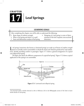
  • 1. Beam shape of uniform strength.• What is leaf spring and where it is used?• Stress and deformation analyses of leaf spring.• Designing of a leaf spring in terms of deter-• mination of the leaf’s requisite cross-sectional dimension. Leaf Springs Leaf springs (sometimes also known as laminated springs) are made up of beams of uniform strength and are normally used in automobiles to absorb the shock and vibration produced by road undula- tions, thereby providing comfort to passengers. Figure 17.1 shows a general arrangement of a typical semi-elliptical leaf spring. The figure also shows the different components of a typical leaf spring1 . Figure 17.2 shows a typical application of the spring in an automobile. Span 2L Camber Eye Master leaf Central clamp Graduated leaves Rebound clip Figure 17.1 Laminated semi-elliptical spring. 1 An interested reader is further directed to refer to Reference (24) in the Bibliography section of the book to know further details of a leaf spring. Learning goaLS After completing this chapter, you will be able to understand the following: 17 Chapter SOM_Chapter 17.indd 741 4/24/2012 8:51:36 PM
  • 2. 742  •  Chapter 17—Leaf SpringS 17.1 Beams of Uniform Strength Let us consider a cantilever beam of a rectangular cross-section loaded at its free-end as shown in Figure 17.3. Now, we know that for such beams, the bending stress is same throughout the length of the beam. If we consider a section at a distance of x from the free-end of the beam as shown in Figure 17.3(a) and show its free-body diagram in Figure 17.3(b), we can find out the magnitude of the bending moment Mx prevailing at that section according to the equation: Mx = −Px (17.1) Obviously, the magnitude of the maximum bending stress is given by: σ = =    MC I Px t bt ( ) 2 1 12 3 Figure 17.2 Leaf spring in an automobile. Figure 17.3 (a) Cantilever beam, (b) free-body diagram of any section. (a) (b) P x Vx Mx x P b t L SOM_Chapter 17.indd 742 4/24/2012 8:51:37 PM
  • 3.  17.2  DefLeCtion of Beam of Uniform Strength  •  743 or σ = 6 2 Px bt (17.2) If we keep the thickness t of the beam section constant and vary the section width b along the beam length in such a way that everywhere the stress is same, say equal to so, then Eq. (17.2) can be used to define b as: b P t x=       6 2 σo or b = lx (17.3) For a given value of P, the parameter λ σ= 6 2 P t/ o is constant and evidently the above Eq. (17.3) suggests that b must then vary linearly with x as shown in the Figure 17.4(a). However, practically, absence of any material at the cantilever tip as shown in Figure 17.4(a) is unacceptable as load P (at the tip of the beam) then cannot be borne by it. This above design of beam is the basic element of a leaf spring. 17.2 Deflection of Beam of Uniform Strength As is evident from the previous Figure 17.4(a), the width of the section at a distance x from the free-end of the beam is given by: b x b L x( ) =     o (a) L b(x) x bo (b) A P b(x) t L A y x O A–A section Figure 17.4 Beam of uniform strength: (a) Top view of beam, (b) front view of beam. SOM_Chapter 17.indd 743 4/24/2012 8:51:38 PM
  • 4. 744  •  Chapter 17—Leaf SpringS and centroidal area moment of inertia is given by: I x b x t( ) ( )= 1 12 3 =       1 12 3 b t L x0 or I x I L x( ) =     0 (17.4) To compute the bending deflection y, we use the flexure equation, Eq. (7.6) of Chapter 7 as: EI y x Mx d d 2 2 = − Although in Chapter 7, we mostly used the above equation for a prismatic beam (i.e., beam with constant EI), now we use it for a non-prismatic beam as well. From Eq. (17.1), as Mx = −Px, we get EI L x y x Pxo d d 2 2 = or EI L y x Po d d     = 2 2 Integrating successively with respect to x: EI L y x Px Co d d     = + 1 (17.5) and EI L y Px C x Co    = + + 2 1 2 2 (17.6) Putting the boundary conditions of y = 0 and dy/dx = 0 at x = L in the above equations, we obtain: C PL C PL 1 2 2 2 = − =and Thus, putting x = 0 in Eq. (17.6) we get the maximum deflection, which is the deflection of the beam at its free end as: EI L Px PLx PL x o    = − + = δmax 2 2 0 2 2 SOM_Chapter 17.indd 744 4/24/2012 8:51:39 PM
  • 5.  17.3  Leaf Spring  •  745 or EI L PLo δmax = 2 2 or δmax = PL EI 3 2 o (17.7) Comparing the free-end deflection of a prismatic cantilever beam with area moment of inertia equal to Io, we note that the above deflection is 1.5 times more. This large deflection under load P is used to make the beam to act as a spring. If instead of a cantilever beam had we considered a simply supported beam, the uniform strength would have led to the geometry known as Lozenge-shaped geometry as shown in Figure 17.5. As each half of the above beam can be modelled as a cantilever beam of uniform strength, we get from Eqs. (17.2) and (17.5) by putting L/2 in place of L and P/2 in place of P, the following relations for the lozenge-shaped beam: σo o = 3 2 PL b t (17.8) δmax = PL LEI 3 3 o 17.3 Leaf Spring A leaf spring or a laminated spring is made up from a beam of uniform strength by cutting, say ng equal strips from the original beam of uniform strength and stacking them one on top of the other. The construction is shown in Figure 17.6. This arrangement of stacked plates produces cantilever-type leaf spring as shown in Figure 17.6(b). In Figure 17.6(a), a triangular plate of width bo (which is a cantilever of uniform strength) is cut into ng equal strips of width b of the central strip (1) where bo = ngb and stacked on as shown in Figure 17.6(b) t t b(x) P bo P/2 P/2 L/2L/2 Figure 17.5 Lozenge-shaped beam. SOM_Chapter 17.indd 745 4/24/2012 8:51:40 PM
  • 6. 746  •  Chapter 17—Leaf SpringS to form a cantilever-type leaf spring. In practice, one or more number of extra full-length plates of uniform width are used to place on top of the graduated plate (1). This is done because to carry the load at the tip of plate (1) we need sufficient material to provide the necessary shear force. However, as plate (1) has a pointed tip, it is not possible to do so if no extra top plate(s) is/are used. This extra plate is known as the master leaf. Yet another variation of the laminated spring, known as the semi-elliptic spring as shown in Figure 17.1. It is used in practice, where a favourable curvature known as cambering is provided to the entire assembly of plates to carry more loads with uniform stress distribution using favourable conditions of residual stresses. The load on the beam due to which this initial curvature can be reduced to zero is called proof load. In the following sections, we provide the analysis of the cantilever-type leaf springs, which is appli- cable also for the semi-elliptic leaf springs. Stress Deformation Analysis for Leaf Springs Let us assume that to the top of the assembly of the ng number of graduated plates of width b, we use nm number of extra full-length master leaf each of uniform width b [i.e., width of the topmost graduated plate (1)]. Thus, essentially, we have a cantilever beam of width nmb and length L connected parallel to the other cantilever beam of uniform strength of width ngb and length L as shown in the Figure 17.7. Clearly, through this arrangement, the applied load P is shared by both the beams. The parallel connectivity of the two beams is modelled as if the beams are connected by a massless rigid link connected at the free ends of the beams. Let Pm and Pg be the loads shared by the master leaf and the graduated leaf, respectively. Clearly, P = Pm + Pg (17.9) Also, we note that the free-end deflections of the beams are equal as they are connected by a rigid link. Hence, P L EI P L EI m m g g 3 3 3 2 = L (a) b1 2 3 (b) 3 2 1 bo = ngb bg/2 Figure 17.6 Cantilever leaf spring. SOM_Chapter 17.indd 746 4/24/2012 8:51:41 PM
  • 7.  17.3  Leaf Spring  •  747 or P P I I m g m g = ⋅ 3 2 where Im and Ig are second moments of area of the master leaf and graduated leaf, respectively. Therefore, P P n bt n bt m g m g =         3 2 1 12 1 12 3 3 or P P n n m g m g = 3 2 (17.10) Solving Eqs. (17.9) and (17.10), we get P n n n Pm m m g Load carried by master leaf= + = 3 3 2 (17.11) Beam of uniform strength Beam of uniform width Massless rigid link Master leaf P t t L nmb ngb LGraduated leaf Figure 17.7 Parallel assembly of cantilever leaf springs. SOM_Chapter 17.indd 747 4/24/2012 8:51:41 PM
  • 8. 748  •  Chapter 17—Leaf SpringS and P n n n Pg g m g Load carried by the graduated leaf= + = 2 3 2 (17.12) Now, maximum stress developed in the beams’ master and graduated leaves are as follows: σm m m = 6 2 P L n bt in the master leaf as it is a rectangular section. Putting Pm from Eq. (17.11), we get σm m g = + 18 3 2 2 ( )n n PL bt (17.13) The above equation gives us the maximum stress developed in the master leaf. Similarly, by putting the expression of Pg in the stress equation, we get the maximum stress in the graduated leaf as σg m g = + 12 3 2 2 n n PL bt (17.14) Comparing Eqs. (17.13) and (17.14), we observe that the stress developed in the master leaf is 50% more than that of the laminated plates. Obviously, this limits the load-carrying capacity of the entire assembly. Hence, in practice, the master leaf is given a different radius of curvature, thereby putting favourable residual stress in it in such a way that when the load is applied to the assembly, an equal stress distribution exists and the system can carry more load. Let us now focus on the deflection of the entire assembly. If dmax is the maximum free-end deflection of the assembly, then from Eq. (17.7): δmax = P L EI g g 3 2 Now from Eq. (17.12) and noting I n btg g= 3 12/ , we get δmax = + 6 2 3 2 3 3 L n bt E n n n P g g m g or δmax ( ) = + 12 3 2 3 3 PL Ebt n nm g (17.15) Equations (17.13) and (17.14) indicate the strength of the spring and Eq. (17.15) gives the rigidity of the assembly. We have to note that the above modelling is approximate, and hence the foregoing equations SOM_Chapter 17.indd 748 4/24/2012 8:51:42 PM
  • 9.  17.3  Leaf Spring  •  749 approximately depict the strength and deformation analysis of the cantilever-type of laminated springs. Recall that these equations are also applicable to the semi-elliptic springs. exampLe 17.1 A cantilever leaf spring is designed to meet the following specifications: Load on the spring = 2 kN Total number of leaves = 8 Number of extra full-length leaves = 2 Width of each leaf = 50 mm Length of spring = 500 mm Design stress in tension = 350 MPa What is the thickness of leaf required to meet the above requirements? Solution Assuming no pre-stressing, we observe that stress in the master leaf is the deciding factor as its stress is 50% more than that in the graduated leaves. From Eq. (17.13), we get σm m g = + 18 1 3 22 PL bt n n So, the thickness of the leaf is given by or t PL b n n = + 18 1 3 2σm m g Putting the necessary values, we get t = + × = ⋅ −( )( )( )( . ) ( )( )( . ) ( ) ( ) . 18 2 10 0 5 350 10 0 05 1 3 2 2 8 10 6 84 3 6 3 mm mm Thus, the required thickness of the plates is 6.84 mm. [Answer] exampLe 17.2 A laminated semi-elliptic spring under a central load of 12 kN is to have an effective length of 1 m and is not allowed to deflect more than 75 mm. The spring has 10 leaves, 2 of which are of full length and are pre-stressed so that all leaves have the same stress after the full load is applied. All leaves have the same width and thickness. The maximum stress in the leaves is not to exceed 350 MPa. Find the width and thickness of the plates. Assume that for the spring material, E = 200 GPa. SOM_Chapter 17.indd 749 4/24/2012 8:51:43 PM
  • 10. 750  •  Chapter 17—Leaf SpringS Solution In the given condition, the stresses are all equal in the leaves. We thus, consider the semi-elliptic spring as two cantilever-type leaf springs connected as shown in Figure 17.8. A C B P/2 = 6 × 10³ NP/2 = 6 × 10³ N P = 12 × 103 N 500 mm = L/2 1000 mm = L Figure 17.8 Arrangement of beams in Example 17.2. As shown in the figure, we consider the portion BC of the beam as the cantilever-type leaf spring with load P/2 and length L/2. Applying the stress and deflection equations, and by noting that stresses are all equal in the leaves, we get σmax = =     = 6 6 4 3 22 2 2 M nbt PL nbt PL nbt where n is the total number of leaves, b denotes plate width and t is plate thickness. (Note that the above equation is applied as the stresses in the leaves are all equal because of pre-stressing.) 3 2 12 10 10 10 350 3 12 10 2 10 350 3 3 2 2 6 ( )( ) ( ) ( )( ) ( )( )bt bt= ⇒ = or bt2 3 5142 86= . mm (1) Again, in Eq. (17.15) by putting P/2 and L/2 in place of P and L, respectively, we get δmax ( ) =         + 12 2 2 3 2 3 3 P L Ebt n nm g = + 3 4 3 2 3 3 PL Ebt n nm g( ) or bt PL E n nm g 3 3 3 4 3 2 = +δmax ( ) = × + × 3 4 12 10 1000 200 10 75 3 2 2 8 3 3 3 ( )( ) ( )( )( ) SOM_Chapter 17.indd 750 4/24/2012 8:51:44 PM
  • 11.  17.3  Leaf Spring  •  751 or bt3 4 27272 73= . mm (2) Now from Eqs. (1) and (2), we get b = 183.1 mm and t = 5.30 mm Thus, the required width and thickness of the plates are 183.1 mm and 5.30 mm, respectively. [Answer] exampLe 17.3 A 100 mm outer diameter steel coil spring having 10 active coils of 2.5 mm diameter wire is in contact with a 750 mm long steel cantilever spring having 6 graduated leaves, 100 mm wide and 6.5 mm thick as shown in Figure 17.9. Assume for steel, E = 200 GPa. (a) Calculate force F, which when gradually applied to the top of the coil spring will cause the cantilever spring to deflect by 25 mm. (b) What will be the maximum shear stress in the coil spring? 750 mm F Figure 17.9 Problem 17.3. Solution We observe from the figure that the coiled spring and the graduated leaf spring are in series arrange- ment and carry the same axial load F. (a) By applying deflection equation, Eq. (17.15) for the leaf spring, we get δmax ( ) = + 12 3 2 3 3 FL Ebt n nm g or F Ebt n n L = +( ) ( )max 3 3 3 2 12 δ m g SOM_Chapter 17.indd 751 4/24/2012 8:51:44 PM
  • 12. 752  •  Chapter 17—Leaf SpringS Now putting the given values in the above expression, we get F = × + ×200 10 100 6 5 25 3 0 2 6 12 750 3 3 3 ( )( )( . ) ( )( ) ( ) N or F = 325.5 N [Answer] (b) Recalling our Eqs. (2.15) and (2.16) from Section 2.5, we get the following results. The maxi- mum shear stress in the coiled spring considering Wahl’s correction factor is τ π max . = − − +     8 4 1 4 4 0 615 3 FD d C C C Putting C D d= = =/ / .100 12 5 8 τ π max ( )( . )( ) ( . ) ( ) ( ) . = − − +       8 325 5 100 12 5 4 8 1 4 8 4 0 615 83 2 N mm or τmax .= 50 25 MPa [Answer] and considering theoretical stress equation, we get τ π max = +     8 1 23 FD d d D = +     8 1 0 5 3 FD d Cπ . = +     ( )( . )( ) ( . ) .8 325 5 100 12 5 1 0 5 83 2 π N mm or τmax .= 45 1 MPa [Answer] Summary In this chapter, we have carefully introduced the concept of beam of uniform strength. From that concept, we went on discussing the use of such beams with constant thickness as spring elements, as they suffer more deflection than their ordi- nary counterparts. These designs (two of which SOM_Chapter 17.indd 752 4/24/2012 8:51:45 PM
  • 13.  nUmeriCaL proBLemS  •  753 have been considered – cantilever type, simply supported type) find their useful practical applica- tions especially in the case of automobiles. A preliminary approximate stress analy- sis of these springs, known as leaf springs, have been presented along with their deformation characteristics also. This chapter will surely be able to introduce the students to a complex design analysis of leaf springs, which they will take up in their Machine Design course. Key terms Leaf spring Laminated spring Uniform strength beam Semi-elliptical leaf spring Rectangular cross-section Cantilever beam Prismatic beam Lozenge-shaped beam Cantilever-type leaf spring Master leaf Graduated leaf Coiled spring Wahl’s correction factor review Questions 1. What is a leaf spring? 2. Explain the function of a leaf spring. 3. Why is a leaf spring used? 4. What is proof load? 5. What do you mean by beam of uniform strength? 6. Discuss the construction of a leaf spring. 7. Derive the stress deformation theory of leaf springs. numerical problems 1. A 1 m long cantilever spring is composed of 8 graduated leaves and 1 additional full- length leaf. The leaves are 45 mm wide. A load of 2000 N at the free-end of the spring causes a deflection of 75 mm. Assuming no pre-stressing, calculate the maximum bending stress developed in the spring. Assume that for the spring material, E = 200 GPa. 2. Repeat the above problem assuming pre- stressing of the additional full-length leaf. 3. For Problem 1, calculate the thickness of the leaf required. SOM_Chapter 17.indd 753 4/24/2012 8:51:46 PM
  • 14. 754  •  Chapter 17—Leaf SpringS answers Numerical Problems 1. 277 MPa 2. 195 MPa 3. 12.3 mm SOM_Chapter 17.indd 754 4/24/2012 8:51:46 PM