Downloaded 936 times
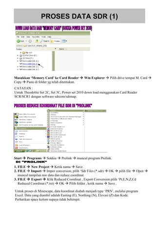
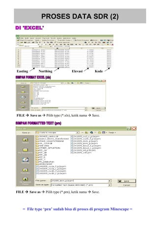
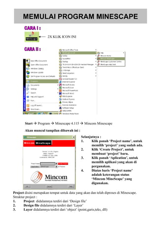


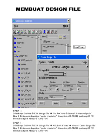

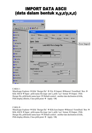
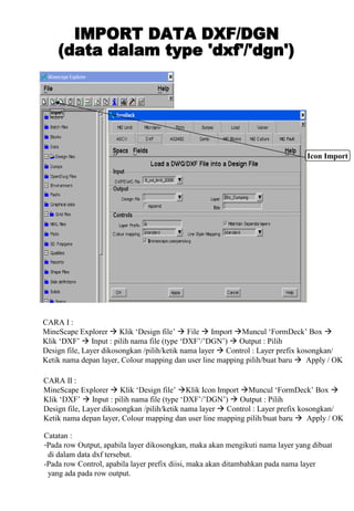

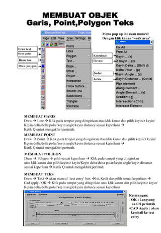
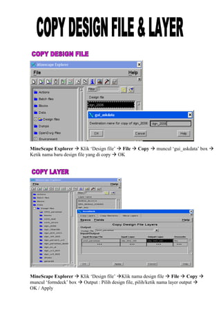
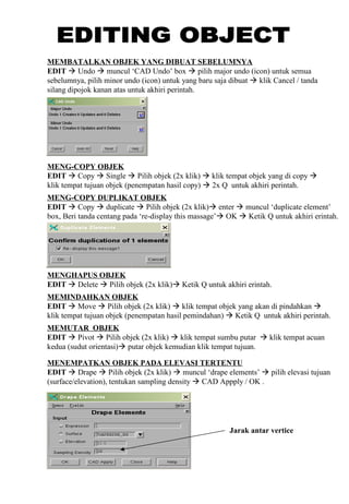
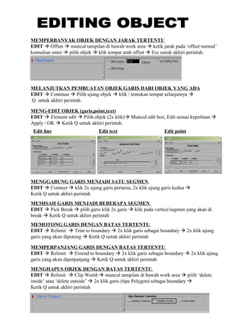
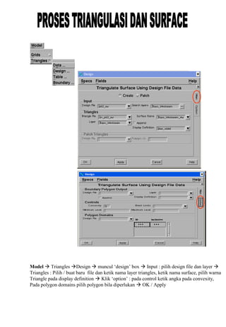

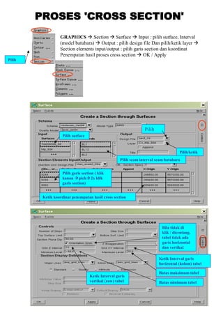
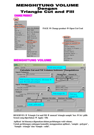

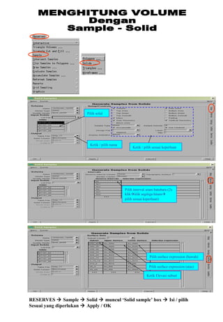


Dokumen tersebut memberikan instruksi langkah-langkah untuk melakukan proses data survei digital (SDR) menggunakan perangkat lunak Minescape untuk keperluan pemetaan tambang, mulai dari pengambilan data SDR, konversi format datanya, pembuatan proyek dan layer di Minescape, hingga proses analisis seperti pembuatan kontur dan potongan-potongan.


![Modul Ajar Kurikulum Berbasis Cinta (KBC) Bahasa Arab Kelas 4 [modulguruku.com]](https://cdn.slidesharecdn.com/ss_thumbnails/modulajarkurikulumberbasiscintakbcbahasaarabkelas4modulguruku-260111161038-33bb50cf-thumbnail.jpg?width=640&height=640&fit=bounds)


![Modul Ajar Kurikulum Berbasis Cinta (KBC) Fikih Kelas 3 [modulguruku.com]](https://cdn.slidesharecdn.com/ss_thumbnails/modulajarkurikulumberbasiscintakbcfikihkelas3modulguruku-260111063151-97bae4f2-thumbnail.jpg?width=640&height=640&fit=bounds)


