Download as PDF, PPTX
![Architecture Week, (2010). Bechtler Museum. [image] Available at: http://www.architectureweek.com/2010/0407/design_4-3.html [Accessed
14 Jun. 2014].
Architecture Week, (2010). Bechtler Museum by Botta. [image] Available at: http://www.architectureweek.com/2010/0217/design_1-2.html
[Accessed 13 Jun. 2014].
ArchwebDWG, (2014). Bechtler Museum of Modern Art. [image] Available at:
http://www.archweb.it/dwg/arch_arredi_famosi/mario_botta/Bechtler_Museum/Bechtler_museum_dwg.htm [Accessed 10 Jun. 2014].
Bechtler Museum of Modern Art. (n.d.). 1st ed. [ebook] Available at: http://www.kingguinn.com/libraries/portfolio/publications/317.pdf
[Accessed 13 Jun. 2014].
Boston Valley Terra Cotta. (2014). 1st ed. [ebook] Institute. Available at:
http://www.swrionline.org/UserFiles/File/Fall09/Project%20Showcase%20Presentations/Architectural%20Terra%20Cotta%20Ventilated%20
Ceramic%20Screen%20Wall%20Systems%20by%20Sheri%20Carter.pdf [Accessed 14 Jun. 2014].
Innovative Manufacturing in Architectural Ceramics. (n.d.). 1st ed. [ebook] New York: Boston Valley. Available at: http://www.triton-
ca.com/pdf_files/BV_TerraClad%20Design%20Guide.pdf [Accessed 13 Jun. 2014].
Steelconstruction.info, (2014). Acoustic performance of floors. [online] Available at:
http://www.steelconstruction.info/Acoustic_performance_of_floors [Accessed 15 Jun. 2014].
Worldarchitecturemap.org, (2014). WAM | Bechtler Museum of Modern Art | Charlotte. [online] Available at:
http://www.worldarchitecturemap.org/buildings/bechtler-museum-of-modern-art [Accessed 15 Jun. 2014].
Reference
20](https://image.slidesharecdn.com/bechtlerconstruction2-140719052004-phpapp02/85/Bechtler-Museum-Construction-20-320.jpg)

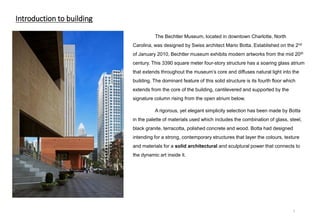
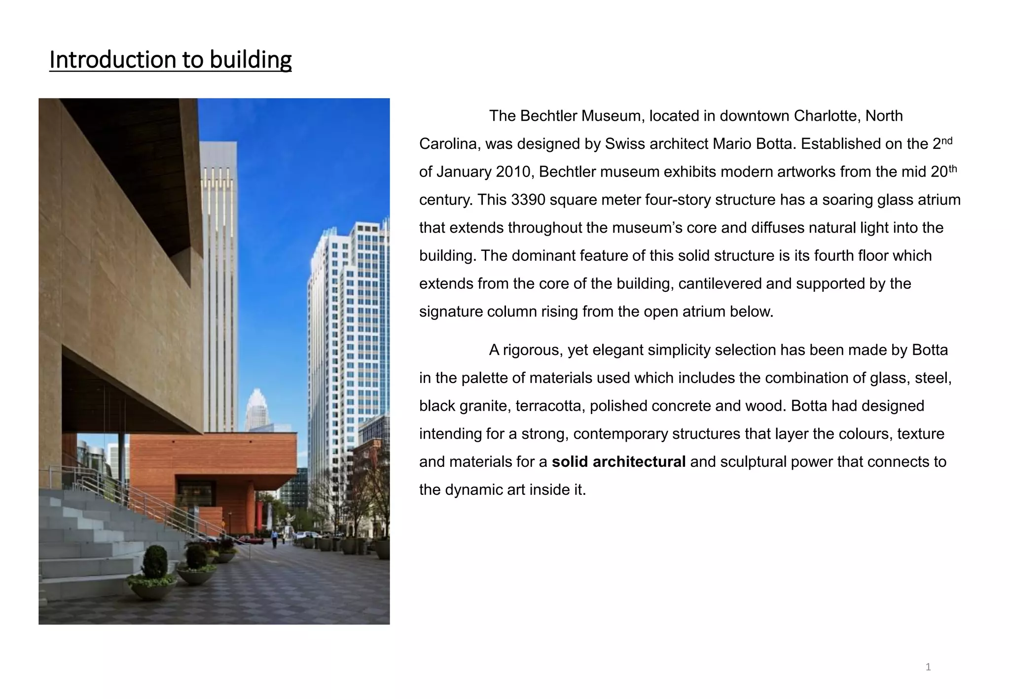
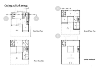
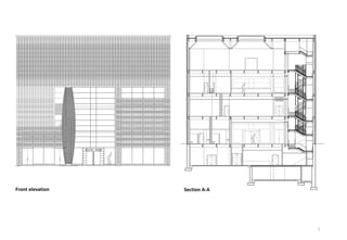
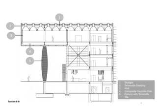
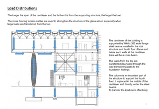
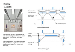
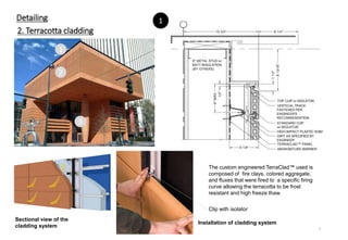
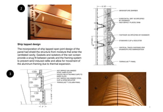
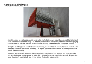
This document provides details on the construction of the Bechtler Museum building in Charlotte, North Carolina. It was designed by Swiss architect Mario Botta and features a soaring glass atrium. The dominant feature is the cantilevered fourth floor, supported by steel beams and a signature column. Materials used include glass, steel, granite, concrete, and terracotta tile cladding. Orthographic drawings and sections show the building plans and structural systems, including the composite concrete slabs, steel beams, and load distributions supporting the cantilever. Construction details are provided for the skylight, terracotta cladding, walls, and load-bearing column.
![Bechtler Museum Report [BCON2]](https://cdn.slidesharecdn.com/ss_thumbnails/bechtlerconstruction2-140718020052-phpapp02-thumbnail.jpg?width=640&height=640&fit=bounds)


