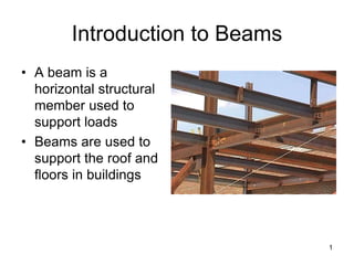
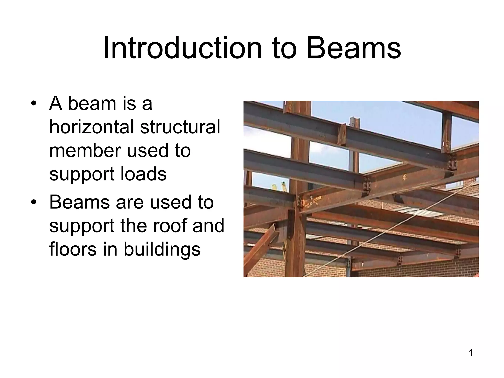
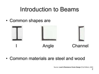
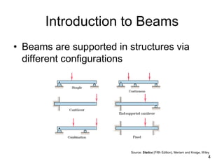
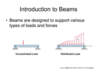
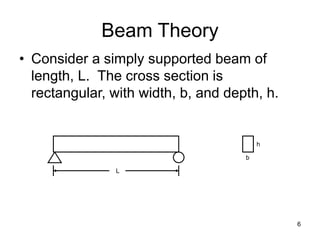
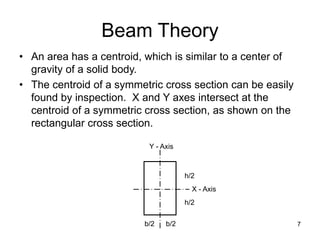
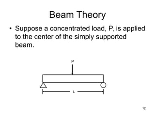
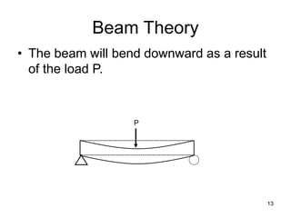
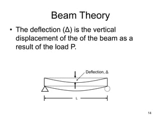
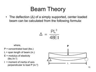
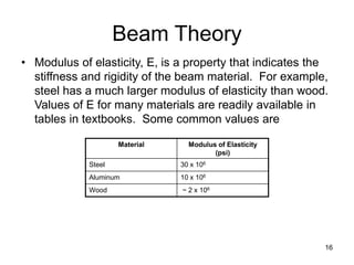
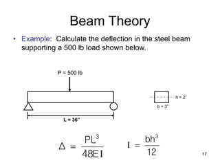
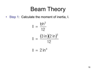
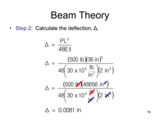
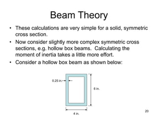
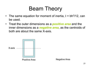
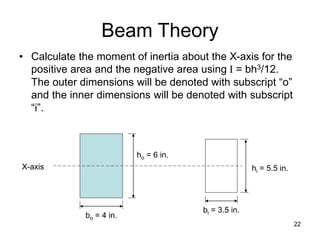
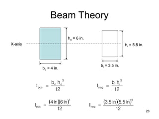
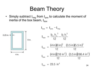
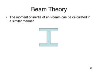
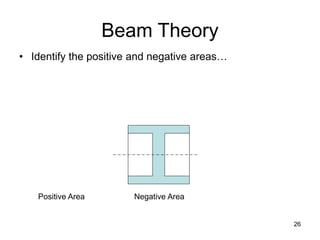
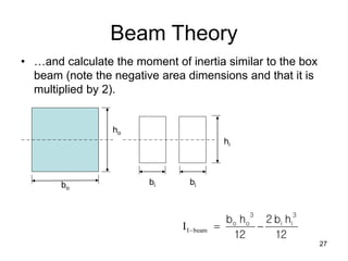
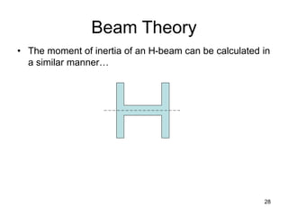
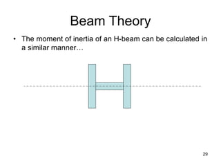
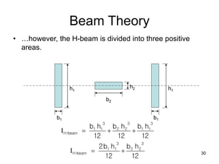
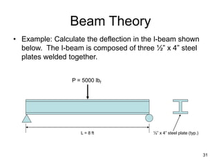
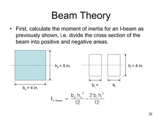
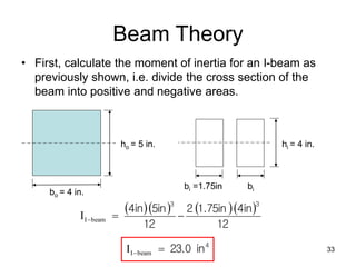
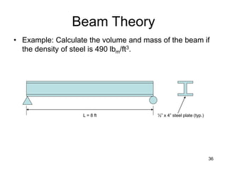
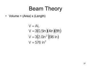
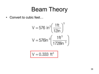
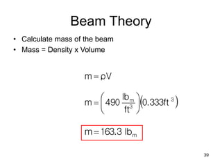
A beam is a horizontal structural member used to support loads in buildings by spanning between supports. Common beam shapes include I-beams, angle beams, and channel beams, which are usually made of steel or wood. The key parts of a beam are the flanges and web. Beams can support concentrated or distributed loads. Beam theory involves calculating the beam's moment of inertia and deflection under loads using properties like the modulus of elasticity. More complex beam shapes like box beams and H-beams calculate moment of inertia by dividing the cross-section into positive and negative areas.