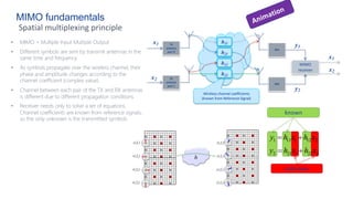
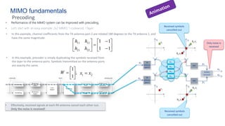
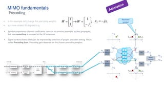
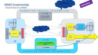
1. Precoding improves MIMO performance by applying weighting to symbols transmitted from each antenna port. This changes the effective channel between transmit antennas and receive antennas.
2. By properly selecting precoding weights, signals from different transmit antennas can add constructively at the receiver, improving signal strength. Weights can also be selected to cancel out interference between streams.
3. Common precoding techniques include maximum ratio transmission, which maximizes received power, and zero forcing, which cancels interference between streams at the cost of reduced power. Precoding weights are selected based on channel state information obtained from reference signals.
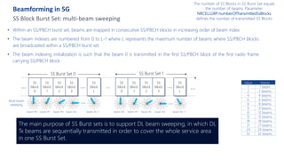
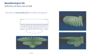
Ultra-Wide Band (UWB) is a communication technology used in wireless networking to achieve high bandwidth connections with low power spectral density.
- What is UWB?
- Why UWB?
- How it works?
- Conclusion
Ultra-Wide Band (UWB) is a communication technology used in wireless networking to achieve high bandwidth connections with low power spectral density.
- What is UWB?
- Why UWB?
- How it works?
- Conclusion
Technology Manager Andreas Roessler covers 5G basics in this keynote presentation at the RF Lumination 2019 conference in February 2019.
RF Lumination 2019
"Meet 158+ years of RF design & test expertise at one event. If they can't answer your question, it must be a really good question!"
Watch all the presentations here:
https://www.rohde-schwarz-usa.com/RFLuminationContent.html
Andreas Roessler is the Rohde & Schwarz Technology Manager focused on UMTS Long Term Evolution (LTE) and LTE-Advanced. With responsibility for the strategic marketing and product portfolio development for LTE/LTE-Advanced, Andreas follows the standardization process in 3GPP very closely, particularly on core specifications as well as protocol conformance, RRM and RF conformance specifications for device and base stations testing. He graduated from Otto-von-Guericke University in Magdeburg, Germany, and received a Master's Degree in communication engineering.
Frequency Independent Antennas:
Wide band antennas
Frequency independent bandwidth in octave range
Broadband antennas
Frequency independent bandwidth in the range 40:1
Multiband antennas
Antenna resonate at different frequencies.
This thesis focuses on mobile phones antenna design with brief description about the historical development, basic parameters and the types of antennas which are used in mobile phones. Mobile phones antenna design section consists of two proposed PIFA antennas. The first design concerns a single band antenna with resonant frequency at GPS frequency (1.575GHz). The first model is designed with main consideration that is to have the lower possible PIFA single band dimensions with reasonable return loss (S11) and the efficiencies. Second design concerns in a wideband PIFA antenna which cover the range from 1800MHz to 2600MHz. This range covers certain important bands: GSM (1800MHz & 1900MHz), UMTS (2100MHz), Bluetooth & Wi-Fi (2.4GHz) and LTE system (2.3GHz, 2.5GHz, and 2.6GHz). The wideband PIFA design is achieved by using slotted ground plane technique. The simulations for both models are performed in COMSOL Multiphysics.
The last two parts of the thesis present the problems of mobile phones antenna. Starting with Specific absorption rate (SAR) problem, efficiency of Mobile phones antenna, and hand-held environment.
ULTRA WIDE BAND TECHNOLOGY
BODY AREA NETWORKS
BW ³ 500 MHz regardless of fractional BW
UWB is a form of extremely wide spread spectrum where RF energy is spread over gigahertz of spectrum
Wider than any narrowband system by orders of magnitude
Power seen by a narrowband system is a fraction of the total UWB power
UWB signals can be designed to look like imperceptible random noise to conventional radios
Frequency-independent (FI) antennas are radiating structures capable of maintaining consistent impedance and pattern characteristics over multiple-decade bandwidths. Their finite size limits the lowest frequency of operation, and the finite precision of the center region bounds the highest frequency of operation.
An overview of 5G NR key technical features and enhancements for massive MIMO, mmWave, etc.
Presented by Yinan Qi, Samsung Electronics R&D Institute UK at Cambridge Wireless event Radio technology for 5G – making it work
*** SHARED WITH PERMISSION ***
This slide describe the techniques of digital modulation and Bandwidth Efficiency:
The first null bandwidth of M-ary PSK signals decrease as M increases while Rb is held constant.
Therefore, as the value of M increases, the bandwidth efficiency also increases.
Bandwidth enhancement of rectangular microstrip patch antenna using slotsIOSR Journals
In this paper, a new design of rectangular microstrip patch antenna (RMPA) without slot, with slots
and array is proposed and analyzed. The designed antenna has been simulated using HFSS software. The
simulated results for return loss, radiation pattern and gain are presented and discussed. The bandwidth of
proposed antenna is 2.4GHz-5.9GHz for VSWR(voltage standing wave ratio)<2><-
10dB return loss as an acceptable reference in wireless applications which cover worldwide interoperability for
microwave access (WiMAX) and wireless local area network (WLAN) and other applications. Gain of 10dB is
achieved for antenna array.
Bandwidth enhancement of rectangular microstrip patch antenna using slotsIOSR Journals
Abstract : In this paper, a new design of rectangular microstrip patch antenna (RMPA) without slot, with slots and array is proposed and analyzed. The designed antenna has been simulated using HFSS software. The simulated results for return loss, radiation pattern and gain are presented and discussed. The bandwidth of proposed antenna is 2.4GHz-5.9GHz for VSWR(voltage standing wave ratio)<2><-10dB return loss as an acceptable reference in wireless applications which cover worldwide interoperability for microwave access (WiMAX) and wireless local area network (WLAN) and other applications. Gain of 10dB is achieved for antenna array. Keywords- Array, Microstrip antenna, WLAN, WiMAX
A Compact Reconfigurable Dual Band-notched Ultra-wideband Antenna using Varac...TELKOMNIKA JOURNAL
In this paper, a reconfigurable dual band-notched ultra-wideband (UWB) antenna is presented.
The antenna design consists of a circular shape with two pairs of the L-resonator. To realize the notch
characteristics in WLAN at 5.2 GHz and 5.8 GHz bands, the half wavelength of the L-resonator is
introduced in the design. The T-shaped notch is etched in the ground to enhance the bandwidth which
covers the UWB operating frequency range from 3.219–10.863 GHz. The proposed reconfigurable dual
band-notched UWB antenna shows good impedance matching for the simulated in the physical layout.
Furthermore, the proposed antenna has a compact size of 37.6x28 mm2. This proposed reconfigurable
design can provide an alternative solution for the wireless system in the designing of a band-notched
antenna with a good tuning capability.
Low-Power D-Band CMOS Amplifier for Ultrahigh-Speed Wireless CommunicationsIJECEIAES
This paper presents a low-power D-Band amplifier suitable for ultrahigh-speed wireless communications. The three-stage fully differential amplifier with capacitive neutralization is fabricated in 40 nm CMOS provided by TSMC. Measurement results show that the Dband amplifier obtains a peak gain of 9.6 dB over a -3 dB bandwidth from 138 GHz to 164.5 GHz. It exhibits an output 1 dB compression point (OP1dB) of 1.5 dBm at the center frequency of 150 GHz. The amplifier consumes a low power of 27.3 mW from a 0.7 V supply voltage while its core occupies a chip area of 0.06 mm 2 .
IJRET : International Journal of Research in Engineering and Technology is an international peer reviewed, online journal published by eSAT Publishing House for the enhancement of research in various disciplines of Engineering and Technology. The aim and scope of the journal is to provide an academic medium and an important reference for the advancement and dissemination of research results that support high-level learning, teaching and research in the fields of Engineering and Technology. We bring together Scientists, Academician, Field Engineers, Scholars and Students of related fields of Engineering and Technology.
Triple Band Integrated Microstrip-Fed UWB Antenna for GSM, Radar and Satellit...theijes
A triple band integrated ultra-wideband (UWB) antenna is proposed in this paper. This proposed antenna covers UWB frequency spectrum of 3.1 – 10.6 GHz as well as other three frequencies bands namely 2 GHz, 11 GHz and 15 GHz for GSM, radar and satellite communication applications respectively. The antenna consists of circular patch, substrate and ground structures. The circular patch is circularly etched on the top surface of substrate with appropriate dimension to achieve UWB spectrum. A thin strip is connected to the rectangular feed line with circular patch. The rectangular ground plane is designed on the back side of antenna with small slots. The proposed antenna is small in dimension and square type. The antenna is designed with the help of FR4 epoxy substrate with relative permittivity of 4.4. The dimension of proposed antenna is 30 mm × 30 mm × 1.6 mm. A 50 Ω microstrip feed line is used to feed the proposed antenna. The simulated results of the proposed antenna are under the standard parameters from 1.8 GHz - 16 GHz frequency bandwidth having return loss < - 10 dB and VSWR ≤ 2. The return losses are -26 dB, -29 dB and -17 dB at 2 GHz, 11 GHz and 15 GHz respectively. Ansoft high frequency structure simulator (HFSS) tool is used for the designing and analysis of the proposed antenna.
DUAL BAND F-ANTENNA FOR EUROPE AND NORTH AMERICAijwmn
A single antenna for multiple bands are always beneficial from the design point of view. Here a single antenna which is fundamentally inverted F antenna is used, the uniqueness of the design is that , it uses trap technique to produce dual resonance from a single inverted F antenna . The trap used to block the current due to some frequencies and passes the current contributed by other frequencies. So in short , this trap is like a RF filter which has some passband as well as stop band. This trap approach uses a LC network to achieve this design goal .The two bands of interest are 865-870 MHz and 902-928 MHz .. The challenge of this design is that the frequency separation of the two bands is very small. In this case, and also the extra section for low frequency band is too small. Then, the influence of trap LC component variation due to tolerance to the two resonant frequencies is big, and so it is difficult to achieve good in band return loss within the LC tolerance. This is the main difficulty of this design. This issue is resolved by placing the low band section away from the end of the antenna. The antenna is designed on FR4 substrate material having thickness of 1.6 mm and hence it is a low cost solution which could use in various commercial applications which follows these bands.
2009 IEEE AP-S-Compact Coaxial-Line-Fed Printed Monopole Antenna for Lower-Ba...Saou-Wen Su
A compact, printed, ultrawideband (UWB) monopole antenna suitable to be as an internal antenna attractive for future UWB applications is demonstrated. The proposed antenna is of a small form factor with the dimensions 6 mm × 33 mm and can easily be fed by 50-ohms mini-cable line. The antenna mainly comprises a monopole antenna, a feeding strip and a ground plane, all printed on a small FR4 substrate. The monopole antenna is printed on both layers of the substrate with an end portion on the back for control of the first/lower resonant mode of the antenna. The feeding strip in between the monopole antenna and the ground plane is further offset to achieve better impedance matching and proper upper-edge operating frequency. With the proposed antenna structure, which provides an operating bandwidth of larger than 2.7 GHz, the impedance bandwidth by 10-dB return loss can easily cover the 3.1–4.85 GHz band, the lower band of the UWB operation.
A Multiband Printed Antenna Suitable for Wireless ApplicationsTELKOMNIKA JOURNAL
This study deals with a new research work on a low cost multiband printed antenna
which can be used for three operating frequency bands GSM900/PCS/WIFI/Bluetooth. The
achieved antenna is mounted on an FR-4 substrate. In this study, the solts technique is used to
obtain the multiband behavior. The different solts are inserted in the radiator face and the back
face that is the ground. The whole circuit is optimized taking into account the good matching of
the input impedance in the operating frequency bands with a stable radiation pattern. In order to
optimize the proposed antenna structure we have used CST-MW and to compare the obtained
simulation results we have conducted another electromagnetic simulation by using HFSS
solver. The final circuit validated into simulation has been fabricated and tested which permits to
validate the proposed multiband antenna.
Connector Corner: Automate dynamic content and events by pushing a buttonDianaGray10
Here is something new! In our next Connector Corner webinar, we will demonstrate how you can use a single workflow to:
Create a campaign using Mailchimp with merge tags/fields
Send an interactive Slack channel message (using buttons)
Have the message received by managers and peers along with a test email for review
But there’s more:
In a second workflow supporting the same use case, you’ll see:
Your campaign sent to target colleagues for approval
If the “Approve” button is clicked, a Jira/Zendesk ticket is created for the marketing design team
But—if the “Reject” button is pushed, colleagues will be alerted via Slack message
Join us to learn more about this new, human-in-the-loop capability, brought to you by Integration Service connectors.
And...
Speakers:
Akshay Agnihotri, Product Manager
Charlie Greenberg, Host
Key Trends Shaping the Future of Infrastructure.pdfCheryl Hung
Keynote at DIGIT West Expo, Glasgow on 29 May 2024.
Cheryl Hung, ochery.com
Sr Director, Infrastructure Ecosystem, Arm.
The key trends across hardware, cloud and open-source; exploring how these areas are likely to mature and develop over the short and long-term, and then considering how organisations can position themselves to adapt and thrive.
Kubernetes & AI - Beauty and the Beast !?! @KCD Istanbul 2024Tobias Schneck
As AI technology is pushing into IT I was wondering myself, as an “infrastructure container kubernetes guy”, how get this fancy AI technology get managed from an infrastructure operational view? Is it possible to apply our lovely cloud native principals as well? What benefit’s both technologies could bring to each other?
Let me take this questions and provide you a short journey through existing deployment models and use cases for AI software. On practical examples, we discuss what cloud/on-premise strategy we may need for applying it to our own infrastructure to get it to work from an enterprise perspective. I want to give an overview about infrastructure requirements and technologies, what could be beneficial or limiting your AI use cases in an enterprise environment. An interactive Demo will give you some insides, what approaches I got already working for real.
Generating a custom Ruby SDK for your web service or Rails API using Smithyg2nightmarescribd
Have you ever wanted a Ruby client API to communicate with your web service? Smithy is a protocol-agnostic language for defining services and SDKs. Smithy Ruby is an implementation of Smithy that generates a Ruby SDK using a Smithy model. In this talk, we will explore Smithy and Smithy Ruby to learn how to generate custom feature-rich SDKs that can communicate with any web service, such as a Rails JSON API.
Securing your Kubernetes cluster_ a step-by-step guide to success !KatiaHIMEUR1
Today, after several years of existence, an extremely active community and an ultra-dynamic ecosystem, Kubernetes has established itself as the de facto standard in container orchestration. Thanks to a wide range of managed services, it has never been so easy to set up a ready-to-use Kubernetes cluster.
However, this ease of use means that the subject of security in Kubernetes is often left for later, or even neglected. This exposes companies to significant risks.
In this talk, I'll show you step-by-step how to secure your Kubernetes cluster for greater peace of mind and reliability.
JMeter webinar - integration with InfluxDB and GrafanaRTTS
Watch this recorded webinar about real-time monitoring of application performance. See how to integrate Apache JMeter, the open-source leader in performance testing, with InfluxDB, the open-source time-series database, and Grafana, the open-source analytics and visualization application.
In this webinar, we will review the benefits of leveraging InfluxDB and Grafana when executing load tests and demonstrate how these tools are used to visualize performance metrics.
Length: 30 minutes
Session Overview
-------------------------------------------
During this webinar, we will cover the following topics while demonstrating the integrations of JMeter, InfluxDB and Grafana:
- What out-of-the-box solutions are available for real-time monitoring JMeter tests?
- What are the benefits of integrating InfluxDB and Grafana into the load testing stack?
- Which features are provided by Grafana?
- Demonstration of InfluxDB and Grafana using a practice web application
To view the webinar recording, go to:
https://www.rttsweb.com/jmeter-integration-webinar
Essentials of Automations: Optimizing FME Workflows with ParametersSafe Software
Are you looking to streamline your workflows and boost your projects’ efficiency? Do you find yourself searching for ways to add flexibility and control over your FME workflows? If so, you’re in the right place.
Join us for an insightful dive into the world of FME parameters, a critical element in optimizing workflow efficiency. This webinar marks the beginning of our three-part “Essentials of Automation” series. This first webinar is designed to equip you with the knowledge and skills to utilize parameters effectively: enhancing the flexibility, maintainability, and user control of your FME projects.
Here’s what you’ll gain:
- Essentials of FME Parameters: Understand the pivotal role of parameters, including Reader/Writer, Transformer, User, and FME Flow categories. Discover how they are the key to unlocking automation and optimization within your workflows.
- Practical Applications in FME Form: Delve into key user parameter types including choice, connections, and file URLs. Allow users to control how a workflow runs, making your workflows more reusable. Learn to import values and deliver the best user experience for your workflows while enhancing accuracy.
- Optimization Strategies in FME Flow: Explore the creation and strategic deployment of parameters in FME Flow, including the use of deployment and geometry parameters, to maximize workflow efficiency.
- Pro Tips for Success: Gain insights on parameterizing connections and leveraging new features like Conditional Visibility for clarity and simplicity.
We’ll wrap up with a glimpse into future webinars, followed by a Q&A session to address your specific questions surrounding this topic.
Don’t miss this opportunity to elevate your FME expertise and drive your projects to new heights of efficiency.
State of ICS and IoT Cyber Threat Landscape Report 2024 previewPrayukth K V
The IoT and OT threat landscape report has been prepared by the Threat Research Team at Sectrio using data from Sectrio, cyber threat intelligence farming facilities spread across over 85 cities around the world. In addition, Sectrio also runs AI-based advanced threat and payload engagement facilities that serve as sinks to attract and engage sophisticated threat actors, and newer malware including new variants and latent threats that are at an earlier stage of development.
The latest edition of the OT/ICS and IoT security Threat Landscape Report 2024 also covers:
State of global ICS asset and network exposure
Sectoral targets and attacks as well as the cost of ransom
Global APT activity, AI usage, actor and tactic profiles, and implications
Rise in volumes of AI-powered cyberattacks
Major cyber events in 2024
Malware and malicious payload trends
Cyberattack types and targets
Vulnerability exploit attempts on CVEs
Attacks on counties – USA
Expansion of bot farms – how, where, and why
In-depth analysis of the cyber threat landscape across North America, South America, Europe, APAC, and the Middle East
Why are attacks on smart factories rising?
Cyber risk predictions
Axis of attacks – Europe
Systemic attacks in the Middle East
Download the full report from here:
https://sectrio.com/resources/ot-threat-landscape-reports/sectrio-releases-ot-ics-and-iot-security-threat-landscape-report-2024/
Accelerate your Kubernetes clusters with Varnish CachingThijs Feryn
A presentation about the usage and availability of Varnish on Kubernetes. This talk explores the capabilities of Varnish caching and shows how to use the Varnish Helm chart to deploy it to Kubernetes.
This presentation was delivered at K8SUG Singapore. See https://feryn.eu/presentations/accelerate-your-kubernetes-clusters-with-varnish-caching-k8sug-singapore-28-2024 for more details.
Epistemic Interaction - tuning interfaces to provide information for AI supportAlan Dix
Paper presented at SYNERGY workshop at AVI 2024, Genoa, Italy. 3rd June 2024
https://alandix.com/academic/papers/synergy2024-epistemic/
As machine learning integrates deeper into human-computer interactions, the concept of epistemic interaction emerges, aiming to refine these interactions to enhance system adaptability. This approach encourages minor, intentional adjustments in user behaviour to enrich the data available for system learning. This paper introduces epistemic interaction within the context of human-system communication, illustrating how deliberate interaction design can improve system understanding and adaptation. Through concrete examples, we demonstrate the potential of epistemic interaction to significantly advance human-computer interaction by leveraging intuitive human communication strategies to inform system design and functionality, offering a novel pathway for enriching user-system engagements.
2. Beamforming in 5G
Internal
Frequency vs. Pathloss vs Beamwidth
Free Space Propagation
( )2
2
4 r
P
G
G
P t
t
r
r
p
l
=
Pathloss proportional to the square of wave lenght
• Where does the power go?
Effective area of radiating element is proportional to square wavelength
Solution : Increase number of radiators per polarization, when going to higher
frequencies.
Drawback: beamwidth becomes smaller with higher antenna gain (higher number of
radiators)
Antenna does not cover whole sector at once anymore.
Special methods are needed for Broadcast (BCH) and Random Access (RACH).
Adaptive user tracking needed.
3. Beamforming in 5G
Internal
Beamforming Principle
Waves transmitted from multiple antennas will add constructively/destructively in space. By changing the phases and amplitudes
of the individual antennas we can change the azimuths of these specific areas → beam pattern
4. Beamforming in 5G
Internal
Beamforming Principle
Waves transmitted from multiple antennas will add constructively/destructively in space. By changing the phases and amplitudes
of the individual antennas we can change the azimuths of these specific areas → beam pattern
5. Beamforming in 5G
Internal
Grid of Beams principle
gNB operates on a set of predefined beams in UL and DL.
Sets of beam weights are stored in the RU and beam
synthesis is taken over by RU.
Beam selection is done by RAU and is indicated to RU by
beam index.
One benefit is reduction of baseband capacity requirement
as calculation of beamforming weights on the fly is very
demanding on the computation power.
The drawback of this solution is non-optimal
beamforming towards users.
Beam weights are shared by orthogonal degree antenna
polarizations, i.e. each beam is cross-polarized and can send
two multiplexed streams.
(RU)
(RF part of gNB-DU)
CPRI/eCPRI One beam
AirScale System Module
ASIK+ABIL
System Module (RAU)
(gNB-DU excl. RF part)
Antenna
elements
MAC scheduler, adapt rank,
MCS, beam, PMI
UE data
Rank,
PMI,
MCS
GoB
Beam_1: {w1,w2… wn}
Beam_2: {w1,w2… wn}
…
Beam_n: {w1,w2… wn}
6. The continuous coverage of the cell area is not there
anymore. The problem is: how to provide common control
channels. These channels need to be heard by all UEs in
the coverage area of the given cell.
The answer is: sweeping. At predefined amounts
of time, the broadcast information is being sent
sequentially across all beams – think about a
lighthouse for a real-world reference.
Beamforming in 5G
Beamforming - common channels coverage
Internal Use
7. Beamforming in 5G
Beamforming
Internal Use
The transmission of
data (& control
information) to any
individual UE is done
with the help of the
narrow beams.
Each individual beam is a signal limited in space (narrow beam), that is intended to reach the user (or
users) placed in the coverage zone of that specific beam but that is not visible to other users (it’s still
detected by others, but with low level)
time
8. Beamforming in 5G
Beamforming – Downlink and uplink
Internal Use
The TDD transmission mode means that there could be DL or UL frames at the same carrier frequency.
The DL and, respectively, UL scheduler will choose the beam direction that will be used during the
incoming TTI, according to the frame type (direction)
time
Downlink transmisson,
followed by uplink
transmission. The
switching can be done
on slot basis, or on
symbol basis
9. Beamforming in 5G
Broadcast transmission - summary
Internal Use
PSS SSS PBCH
PSS PBCH
SSS
PBCH
PBCH
PSS PBCH
SSS
PBCH
PBCH
PSS PBCH
SSS
PBCH
PBCH
PSS PBCH
SSS
PBCH
PBCH
PSS PBCH
SSS
PBCH
PBCH
Below
6GHz
Above
6GHz
2 x
4 x
3 to
6GHz 8 x
64 x*
SS Block
SS Burst SS Burst Set
PSS, SSS and PBCH (carrying
MIB) are time and frequency
multiplexed
That set compose SS Block
in four consecutive OFDM
symbols
Above
6GHz
SS Blocks form SS Burst that is a
set of consecutive SS blocks
SS Bursts compose SS Burst set used
for multi beam sweeping
*Up to 32 according to
NRCELLGRP:numberOfTransmittedSsBlocks
parameter range
10. Beamforming in 5G
SS Block Burst Set: multi-beam sweeping
SS
block
0
SS
block
1
SS
block
2
SS
block
3
SS
block
L
… …
Multi-beam
sweeping
…
• Within an SS/PBCH burst set, beams are mapped in consecutive SS/PBCH blocks in increasing order of beam index
• The beam indexes are numbered from 0 to L-1 where L represents the maximum number of beams where SS/PBCH blocks
are broadcasted within a SS/PBCH burst set
• The beam indexing initialization is such that the beam 0 is transmitted in the first SS/PBCH block of the first radio frame
carrying SS/PBCH block
SS
block
0
SS
block
1
SS
block
2
SS
block
3
SS
block
L
…
The number of SS Blocks in SS Burst Set equals
the number of beams. Parameter
NRCELLGRP:numberOfTransmittedSsBlocks
defines the number of transmitted SS Blocks
…
SS Burst Set 0 SS Burst Set 1
beam #0 beam #1 beam #2 beam #3 beam #L-1 beam #0 beam #1 beam #2 beam #3 beam #L-1
… …
Value Name
1 1 beam
2 2 beams
4 4 beams
6 6 beams
8 8 beams
9 9 beams
12 12 beams
15 15 beams
18 18 beams
21 21 beams
24 24 beams
32 32 beams
The main purpose of SS Burst sets is to support DL beam sweeping, in which DL
Tx beams are sequentially transmitted in order to cover the whole service area
in one SS Burst Set.
11. Beamforming in 5G
Definition of basic sets of SSB
Beam sets and basic beam sets
The basic beam sets shall be defined using the nomenclature #k#l#m ...
the number of columns in a row is given by the respective integer, preceded by the
character '#'
rows are counted from top to bottom, i.e., the first row is the one with highest
pointing beams, the last row is the one with lowest pointing beams
Examples:
• basic beam set #4#4 denotes a beam set with 2 rows and 4 columns in each row
• basic beam set #3#3#2 denotes a beam set with 3 rows, most upper row and
middle row with 3 beams each, lowest row with 2 beams only
Internal Use
basic beam set #4#4
basic beam set #3#3#2
azimuth
elevation
Number of beams in basic beam set must match with number of
transmitted SS blocks set by NRCELLGRP-
numberOfTransmittedSsBlocks parameter
12. Beamforming in 5G
Supported beamsets
Internal
basicBeamSet Beam pattern # of
panel
s
# of
bea
ms
Azimuth
opening
[deg]
Elevation
opening
[deg]
Note
beamSetAbf_32A ooooooooooooooo
oooooooooooooo
O
1 32 -60, 60 87, 123 Valid only for single panel radios
beamSetAbf_32B oooooooooo
ooooooooo
oooooooooo
1 32 -40, 40 72, 108 Valid only for single panel radios
beamSetAbf_32C oooooooooo
ooooooooo
oooooooooo
1 32 -40, 40 72, 108 Valid only for single panel radios
Legacy beam sets defined in 5G19 Analog Beamforming for CPRI
RUs are supported by 1-panel RUs.
Note: Final beamsets may be subject to further optimizations
13. Beamforming in 5G
Definition of basic sets of SSB
Internal
Basic beam set beamSetAbf_32A from different perspectives
14. Beamforming in 5G
Radio Units ‘example’
400 MHz 3 GHz 30 GHz
10 GHz 90 GHz
6 GHz
cmWave mmWave
Carrier BW n * n * 100 MHz 1-2GHz
Duplexing * TDD
Cell size Macro Small Ultra small
higher capacity and massive throughput, noise limitation à
ß continuous coverage, high mobility and reliability, interference limitation
28 GHz 39 GHz
3.5GHz Radio Unit
3.5 GHz 3.7 GHz
3.7GHz Radio Unit
28GHz Radio Unit 39GHz Radio Unit
DIGITAL
Beamforming
• UL/DL 2x2 SU-MIMO
• UL/DL 2x2 SU-MIMO
• DL: 4x4 SU-MIMO / UL: 2x2 SU-MIMO
• 16UL/16DL MU-MIMO
ANALOG
Beamforming
Internal Use
15. Beamforming in 5G
Difference between Analog and Digital Beamforming
Internal Use
• In Analog Beamforming, there is a single TRX per polarization. Beam pattern is obtained by modification of the RF signal
between the TRX and the antenna elements.
• A planar array of 16x16 radiating elements is used. RF signal is modified by an RF Integrated Circuit (RFIC) in the RU.
• This is applicable for FR2 (frequencies above 6 GHz).
…
w1 w3
w2 wn
TRX1
UE data
stream
16. Beamforming in 5G
Difference between Analog and Digital Beamforming
Internal Use
• In Digital Beamforming, beam pattern is synthesized by manipulating weights of the individual TRXs
• Beamforming weights are applied between the fronthaul and TRXs.
• Beamforming weights are applied in RU, while beam selection is done by RAU.
TRX1
TRX2
TRX3
TRXn
UE data
stream …
w1 w3
w2 wn
17. Beamforming in 5G
Beam Refinement
In case of operating with a grid of beam (GoB) and especially with carrier frequencies below 6GHz with limited number
of SSB beams, beam refinement on 5G-NB side is used to achieve higher SINR for a single UE in both DL and UL
direction, as well as better separation of UEs in case multiple UEs are served on the same time and frequency resources,
i.e., MU-MIMO operation.
To enable execution of respective measurements by UEs, CSI-RS have to be transmitted for beam refinement. The
antenna ports used for these CSI-RS have to be mapped to the beams used for refining a respective SSB beam
4 refined beams per SSB beam are implemented.
Internal Use
SSB beam
Refined beams
Beam refinement is activated by setting parameter
NRCELL-beamSet.nrBtsBeamRefinementP2 = true
18. Beamforming in 5G
Example of refined beams
Basic beam set #3#3#2 with refined beams from different perspectives (not
all refined beams shown)
Internal Use
basic beam set #3#3#2
19. Beamforming in 5G
Beam recovery
Internal
In case of beam failure, i.e., the UE may no more be reached via the best beam
last known at gNB side, a procedure to reconnect the UE has to be executed.
1. 5G-UE detects a misaligned serving beam to gNB e.g. by
NACKed UL data sent or by interrupted DL data allocation.
Potential reasons:
• 5G-UE measures the source beam with L1-RSRP below
minimum link budget,
2. 5G-UE measures a new target beam with strongest L1-RSRP
3. 5G-UE starts Beam Recovery by sending Random Access
Preamble on a best target beam
4. UL and DL transmissions are resumed on a new beam
PRACH
20. Beamforming in 5G
Internal
Beam failure and recovery process
gNB UE
SSB
TX
Scan SSB beams
And select best
RX PRACH
Measure SSB associated
PRACH procedure
as in initial access
Initiate PRACH procedure if meet
failure criterion
Periodic
checking
Initial access procedure
• Beam failure detection uses default RRC configuration with
active PDCCH TCI state.
• Failure triggered if SSB RSRP beam meets failure criterion.
• Beam recovery reference signal measurement based on
RRC configuration for CBRA.
• Beam recovery follows initial access PRACH procedure.
TX
21. Beamforming in 5G
Antenna tilt for 2D GoB
introduces a tilt function for RF units with an integrated antenna with 32 or 64 TRX
using a GOB pattern for cmWave frequency range.
The tilt is operator configurable per cell and applied at cell setup as tiltOffset. The
tiltOffset range is +/-13° degrees around the pre-Tilt defined by the HW radio design
and with a step size of 1°.
It is assumed that the shape of GoB beam set is kept, i.e. a possible calculation error
is not exceeding a specific threshold. This ensures that the beam orthogonally
required for later MU operation is not affected
This feature supports in this release CPRI RUs (NRCELL.beamSet.tiltOffset).
Internal Use
RU
tilt
22. 5G MU-MIMO
DL MU-MIMO for Digital Beamforming for CPRI based RUs
UL MU-MIMO for Digital Beamforming for CPRI based RUs
24. MIMO fundamentals
Spatial multiplexing principle
h11
h12
h21
TX
antenna
port 0
TX
antenna
port 1
RX1
RX2
MIMO
receiver
x1
x2
y1
y2
x1
x2
Animation
Wireless channel coefficients
(known from Reference Signal)
2
12
1
11
1 x
h
x
h
y +
=
2
22
1
21
2 x
h
x
h
y +
=
h22
known
unknown
• MIMO = Multiple Input Multiple Output
• Different symbols are sent by transmit antennas in the
same time and frequency
• As symbols propagate over the wireless channel, their
phase and amplitude changes according to the
channel coefficient (complex value)
• Channel between each pair of the TX and RX antennas
is different due to different propagation conditions
• Receiver needs only to solve a set of equations.
Channel coefficients are known from reference signals,
so the only unknown is the transmitted symbols
27. MIMO fundamentals
Precoding
• Performance of the MIMO system can be improved with precoding.
• Let’s start with an easy example: 2x2 MIMO, 1 codeword, 1 layer:
Scrambling
Modulation
mapper
Layer
mapper
Precoding
Resource element
mapper
OFDM signal
generation
Resource element
mapper
OFDM signal
generation
Scrambling
Modulation
mapper
layers antenna ports
codewords
1
-1
1
TX
antenna
port 0
TX
antenna
port 1
RX1
RX2
MIMO
receiver
x1
x2
y1
y2
x1
x2
-1
I
Q
1
x
I
Q
1
11x
h
2
12x
h
I
Q
2
x
I
Q
1
21x
h
2
22x
h
h11
h12
h21
h22
ú
û
ù
ê
ë
é
-
-
=
ú
û
ù
ê
ë
é
1
1
1
1
22
21
12
11
h
h
h
h
• In this example, channel coefficients from the TX antenna port 2 are rotated 180 degrees to the TX antenna 1, and
have the same magnitude:
• Effectively, received signals at each RX antenna cancel each other out.
Only the noise is received!
• In this example, precoder is simply duplicating the symbols received from
the layer to the antenna ports. Symbols transmitted on the antenna ports
are exactly the same.
;
1
1
ú
û
ù
ê
ë
é
=
W
Received symbols
cancelled out
Received symbols
cancelled out
Animation
Only noise is
received
2
1 x
x =
28. MIMO fundamentals
Precoding
Animation
• In this example, let’s change the precoding weights:
• x2 is now rotated 90 degrees to x1
Scrambling
Modulation
mapper
Layer
mapper
Precoding
Resource element
mapper
OFDM signal
generation
Resource element
mapper
OFDM signal
generation
Scrambling
Modulation
mapper
layers antenna ports
codewords
1
-1
1
TX
antenna
port 0
TX
antenna
port 1
RX1
RX2
MIMO
receiver
x1
x2
y1
y2
x1
x2
-1
I
Q
1
x
I
Q
1
11x
h
2
12x
h
I
Q
2
x
I
Q
1
21x
h
2
22x
h
• Symbols experience channel coefficients same as on previous example as they propagate,
but now something is received at the UE antennae.
• Signal to Noise Ratio (SNR) can be improved by selection of proper precoder setting. This is
called Precoding Gain. Precoding gain depends on the chosen precoding weights.
;
1
1
1
ú
û
ù
ê
ë
é
-
=
®
ú
û
ù
ê
ë
é
=
j
W
W
Received
symbol
1
2 jx
x -
=
30. MIMO fundamentals
Closed loop DL MIMO
gNB UE
RF
precoder
layers
RF
Channel
estimation
Rank and
precoding
calculation
codebook
2 3
Part of UCI
“…and this PMI”
I want this rank…”
Animation
7
6
MIMO
control
5
U P L I N K C O N T R O L I N F O R M A T I O N
D O W N L I N K C O N T R O L I N F O R M A T I O N
Part of DCI
“Here is your data, and I used this
number of layers…”
“…and this PMI”
codebook
4
layers
8
PDSCH
receiver
1
9
#
o
f
l
a
y
e
r
s
5GC000531/5
GC000605
CSI-RS
31. MIMO fundamentals
Closed loop UL MIMO
UE gNB
RF
precoder
layers
RF
Channel
estimation
Rank and
precoding
calculation
codebook
Part of DCI
Please send SRS
signal to me
Animation
D O W N P L I N K C O N T R O L I N F O R M A T I O N
D O W N L I N K C O N T R O L I N F O R M A T I O N
Part of DCI
“I want to used this number of
layers…”
“…and this TPMI”
codebook
layers
PUSCH
receiver
5GC000532
SRS
32. DL Closed Loop Transmission (Report Quantity = CRI-RI-PMI-CQI)
DL Closed loop:
gNB transmits CSI-RS and UE reports CSI-RS
feedback (CRI-RI-PMI-CQI).
gNB selects the rank and the precoding matrix
according to the UE's CSI feedback.
33. UL Closed Loop Transmission
Closed Loop 2x2 MIMO
5G18A gNb implements a Codebook based
transmission scheme.
Rank and PMI are decided at gNB based on received UL
reference signals SRS and DMRS on PUSCH.
35. What is “Massive MIMO”?
• Massive MIMO is the extension of traditional MIMO
technology to antenna arrays having a large number of
controllable antennas
• MIMO = Multiple Input Multiple Output = any transmission scheme
involving multiple transmit and multiple receive antennas
– Encompasses all implementations:
» RF/Baseband/Hybrid
– Encompasses all TX/RX processing methodologies:
» Diversity, Beamforming, Spatial multiplexing,
» SU & MU, joint/coordinated transmission/reception, etc.
• Massive è Large number: >> 8
• Controllable antennas: antennas (whether physical or otherwise)
whose signals are adaptable by the PHY layer (e.g., via gain/phase
control)
(0,0) (0,1) (0,N-1)
(M-1,N-1)
……
(M-1,0) (M-1,1)
(1,0) (1,1) (1,N-1)
……
……
……
……
……
……
36. Why “Massive MIMO”
• Benefits:
– Enhance Coverage è High gain adaptive beamforming
• Focus energy more towards the user, increase SINR
– Enhance Capacity è High order spatial multiplexing
• Multiple parallel spatial streams to a single user (SU) or to multiple users (MU)
• Relevance to 5G:
– Lower operating frequencies (e.g., <6GHz) are more interference limited
• LTE already designed for high spectral efficiency (<8 Antenna ports)
• Capacity-enhancing solutions become essential
– Higher operating frequencies (e.g., >>6GHz) have poor path loss
conditions
• Coverage-enhancing solutions become essential
37. 5G Beamforming solutions
Digital BB beamforming
• Mainly for below 6GHz (but also for cmWave)
• Requires RF phase/amplitude calibration of IF+TRX+Filter
• Requires high front haul interface bandwidth
• Requires high number of TRXs (8 … 128)
Digital RF beamforming
• Mainly for above 6GHz (hybrid BF), but also for below 6GHz
• Beamformer implemented in RF module
• Requires RF phase/amplitude calibration of TRX+Filter
• Requires high number of TRXs (8 … 256)
Analog RF beamforming
• For cmWave & mmWave specturm
• Beamformer implemented in RFIC or through lens Antenna
• Requires RF phase/amplitude stability of RFIC
• Requires high number of radiators per array
40. Beam set overview
Beam Set
• One beam set includes those SSB & fine beams which can be used concurrently for some scenario
• In each beam set, both SSB beams and fine beams can have several rows
• Number of beams in each row can be different
• Some overlap between neighbour beams to have good coverage
• Typically more beams for outer part of a cell and less beams for inner part of a cell
𝝋_l
𝝋_r
SSB5
SSB4
SSB3 SSB2
SSB1
SSB0
SSB7
SSB6
Example of 8 SSB beams
𝝋_l
𝝋_r
Example of 32 fine beams
42. mMIMO & BF key features
Digital beamforming
§ Up to 8 x-pol coarse beams
(< 6 GHz)
§ Up to 32 refined beams for
UE specific channels
§ Scheduling of a single UE
per slot per direction and
carrier
DL SU MIMO
§ For digital BF
§ 2 refined x-pol beams are
used to provide 4x4 MIMO
on PDSCH
§ UEs with 2 RX antennas are
supported with 4x2
transmission
DL/UL MU MIMO
§ For digital BF
§ UEs are scheduled at the
same time on the same
frequency resources over
different beams
§ Support of up to
§ 8 UEs with 2x2 SU-
MIMO on DL or UL
§ 4 UEs with 4x2 or 4x4
SU-MIMO on DL
UL SU MIMO
§ For digital BF
§ One refined x-pol beams are
used to provide 2x2 MIMO
on PUSCH
43. MU-MIMO Overview
Before & after MU-MIMO features
Before
• Single user can be scheduled using 2x2 or 4x4 MIMO on
dedicated time and frequency resources
After
• Up to 8 UEs (16 streams) can be scheduled on the same
time and frequency resources using spatial multiplexing
• Peak cell throughput and spectral efficiency increase,
mostly for static users
Customer Confidential
44. MU-MIMO Overview
mMIMO RF at 3.5 GHz
64 antenna elements
dual polarization ±45°
Carrier 100MHz
Baseband Unit
RF calibration
centrally from RM
100MHz carrier
±45°
0.376m
0.536m
2
x
T
R
X
2
x
T
R
X
2
x
T
R
X
M
D
R
D
F
E
F
P
G
A
Q
S
F
P
Q
S
F
P
Q
S
F
P
Q
S
F
P
P
S
U
D
F
E
F
P
G
A
D
F
E
F
P
G
A
D
F
E
F
P
G
A
2
x
T
R
X
RF
module
64TRX
8 x
Filters
Antenna
feed
and
division
network
0.5λ
0.7λ
~0.2m2
4 rows x 8 columns x dual Polarizations
45. MU-MIMO Overview
§ Mechanics
Ÿ Overall dimensions (without
solar shield):
Ÿ H = 850 mm
Ÿ W = 460 mm
Ÿ D = 144 mm
Ÿ Housing material: ALSI 12 ,
Die-casting/Extrusion
Ÿ Weight:~45KG
Ÿ Volume:56.3L
QSFP RJ45
DC IN
• mMIMO RF at 3.5 GHz
46. MU-MIMO Overview
Introduction
• Multiuser MIMO allows to transmit signal to many users in
downlink or uplink at the same time and in the same
frequency resources by using beamforming and spatial
multiplexing.
• It increases cell peak rate, but not user peak rate
• It increases average cell and user throughput
• DL 2x2 MIMO with up to 8 UEs can be co-scheduled per TTI.
If 4X4 MIMO is enabled, up to 4 UEs can be co-scheduled
per TTI.
• UL 2x2 MIMO with up to 8 UEs can be co-scheduled per TTI.
47. When is correlation metric high and when is it low?
• Intuitively, factor is low when beamforming factor Ui and Uj are not similar to each other.
From beamforming perspective, this means that beams of ith and jth UE will point in different
directions.
• The best situation is when correlation is equal to 0, the worst situation is when correlation is
equal to 1.
Pairing algorithm
Correlation
U1 ≠ U2
Low correlation
U1 ≈ U2
High correlation
48. MU-MIMO Receiver
Overview
In 5G18A, the UL receiver is still SU-MIMO PoC receiver. It works well if only one UE is scheduled per TTI.
But to support concurrent UL scheduling for up to 8 UEs, this approach cannot get optimal UL
performance. Even the UL pairing algorithm selects paired UEs which have the maximum orthogonality
with each other.
The non-orthogonality of UL channels between co-scheduled UEs will introduce interference with each
other. The SU-MIMO based receiver cannot well handle this interference. To involve MU-MIMO receiver
to mitigate interference from co-scheduled UEs is the way we need to go.
50. Reference Signal
SRS
Customer
Confidential
Extension of 5GC000532
Before MU
combOffset = 0
cyclicShift = 0
Only one UE can send SRS in one
symbol.
After MU
combOffset = 0 or 1
cyclicShift = 0 ~ 3
Up to 8 UEs can send SRS in one
symbol.
51. Reference Signal
CSI-RS
Customer
Confidential
Extension of 5GC000531
Before MU
other = 000001
Only one UE can measure CSI-RS for
CSI in one symbol.
After MU
other = 000001 ~ 100000
Up to 6 UEs can measure CSI-RS for CSI
in one symbol.