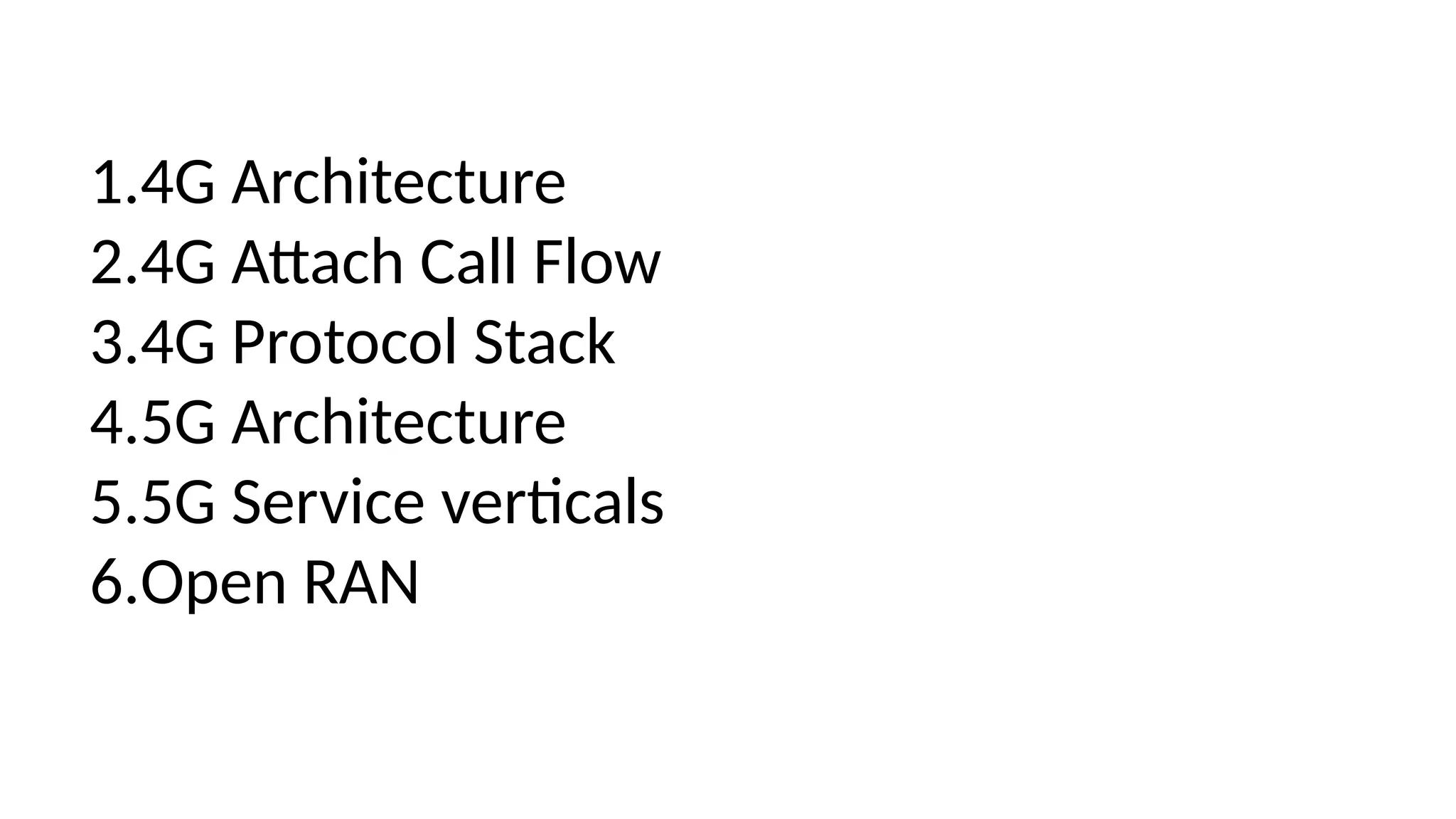
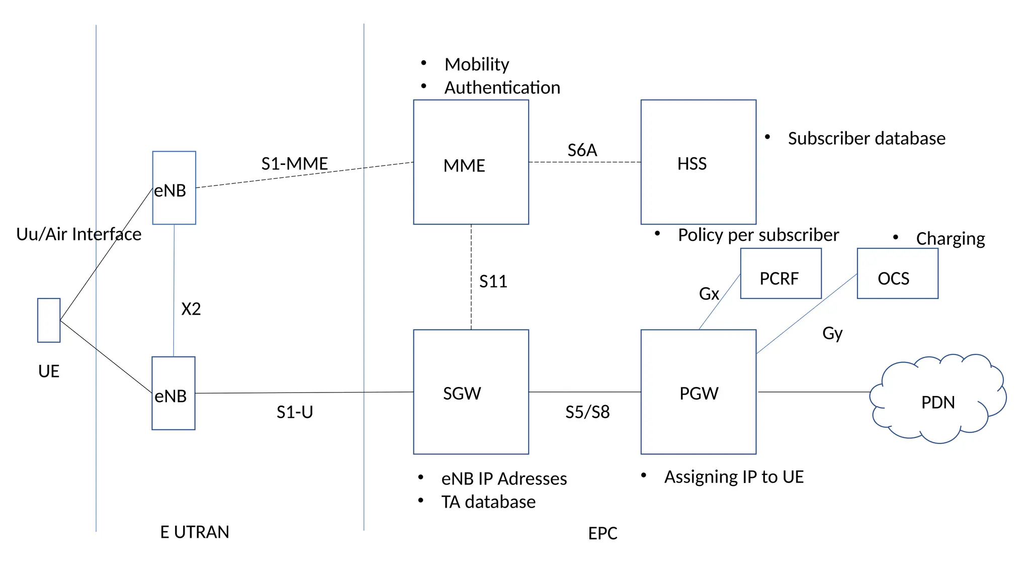
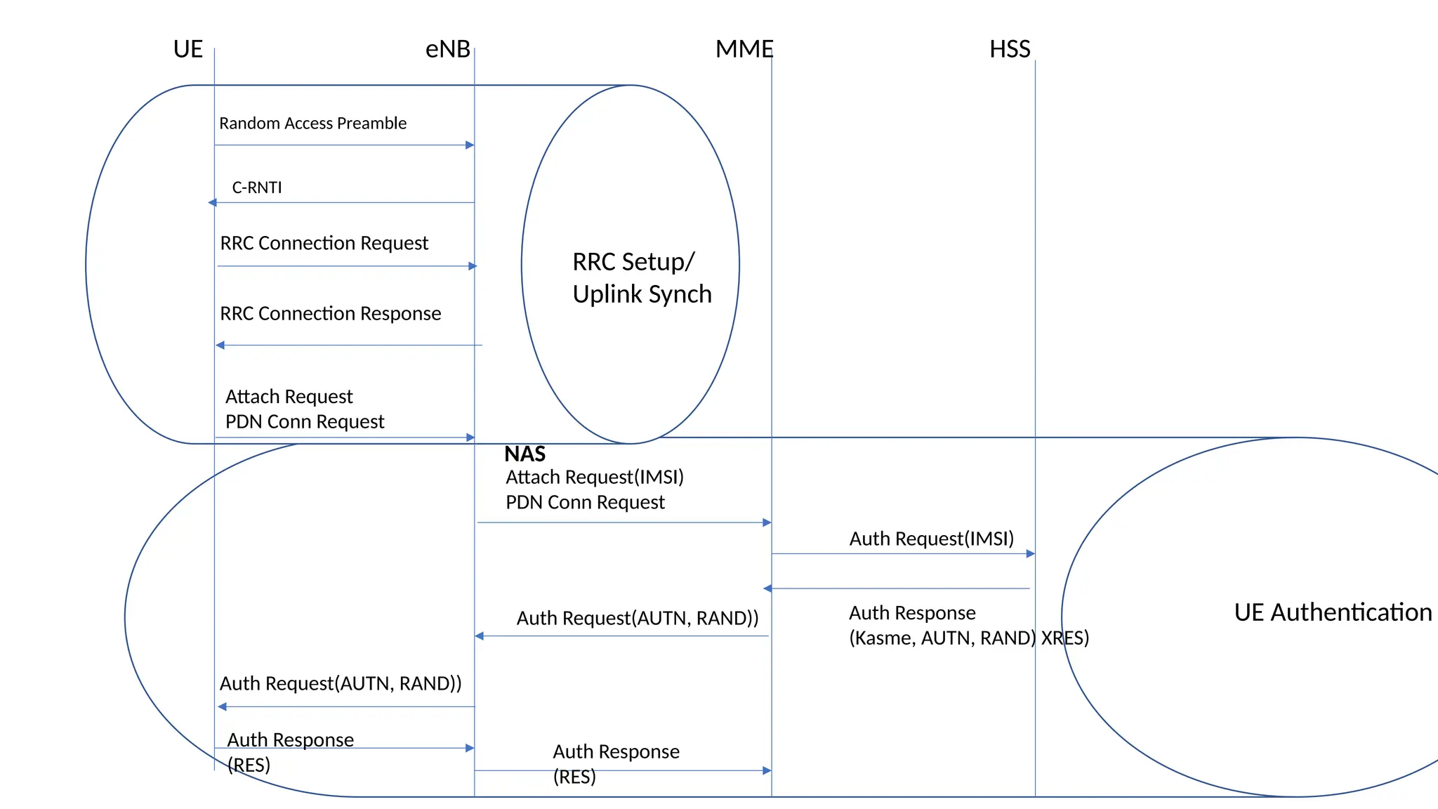
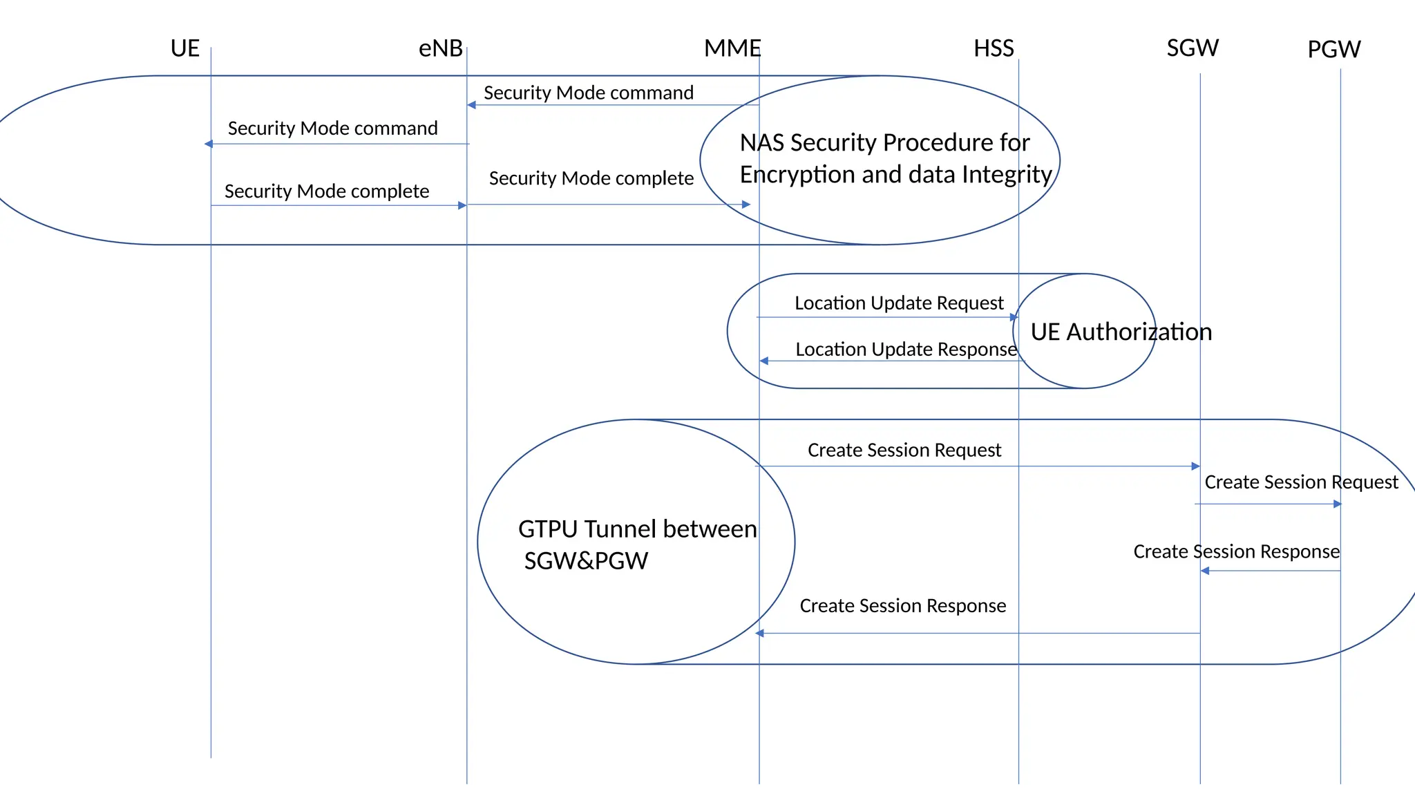
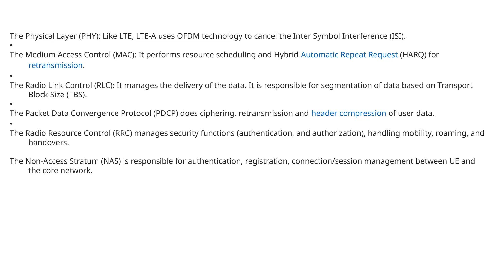
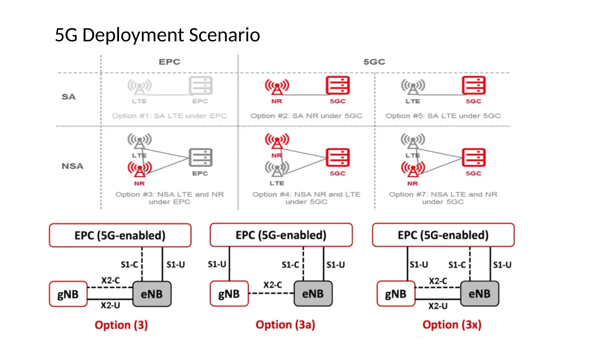
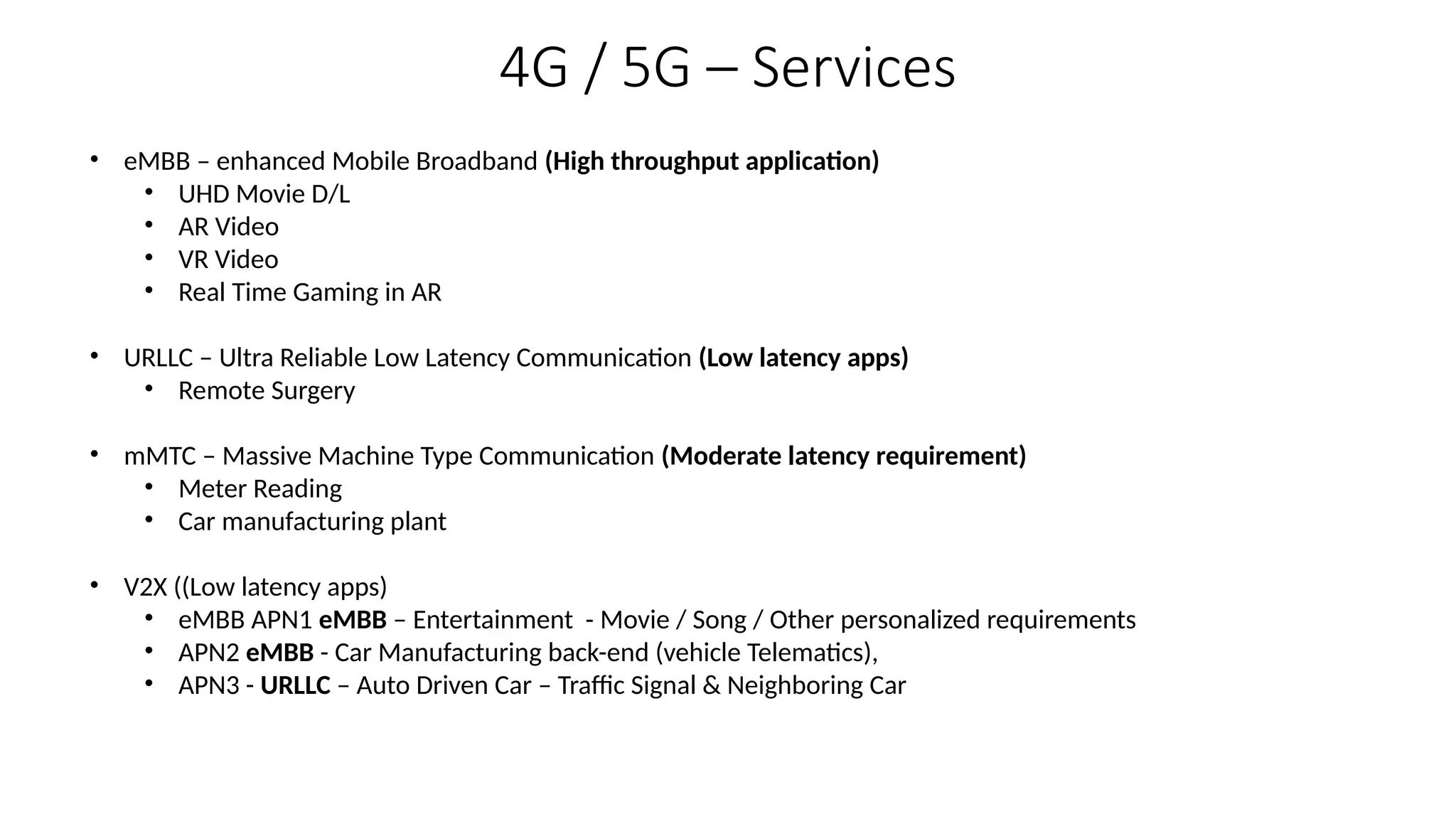
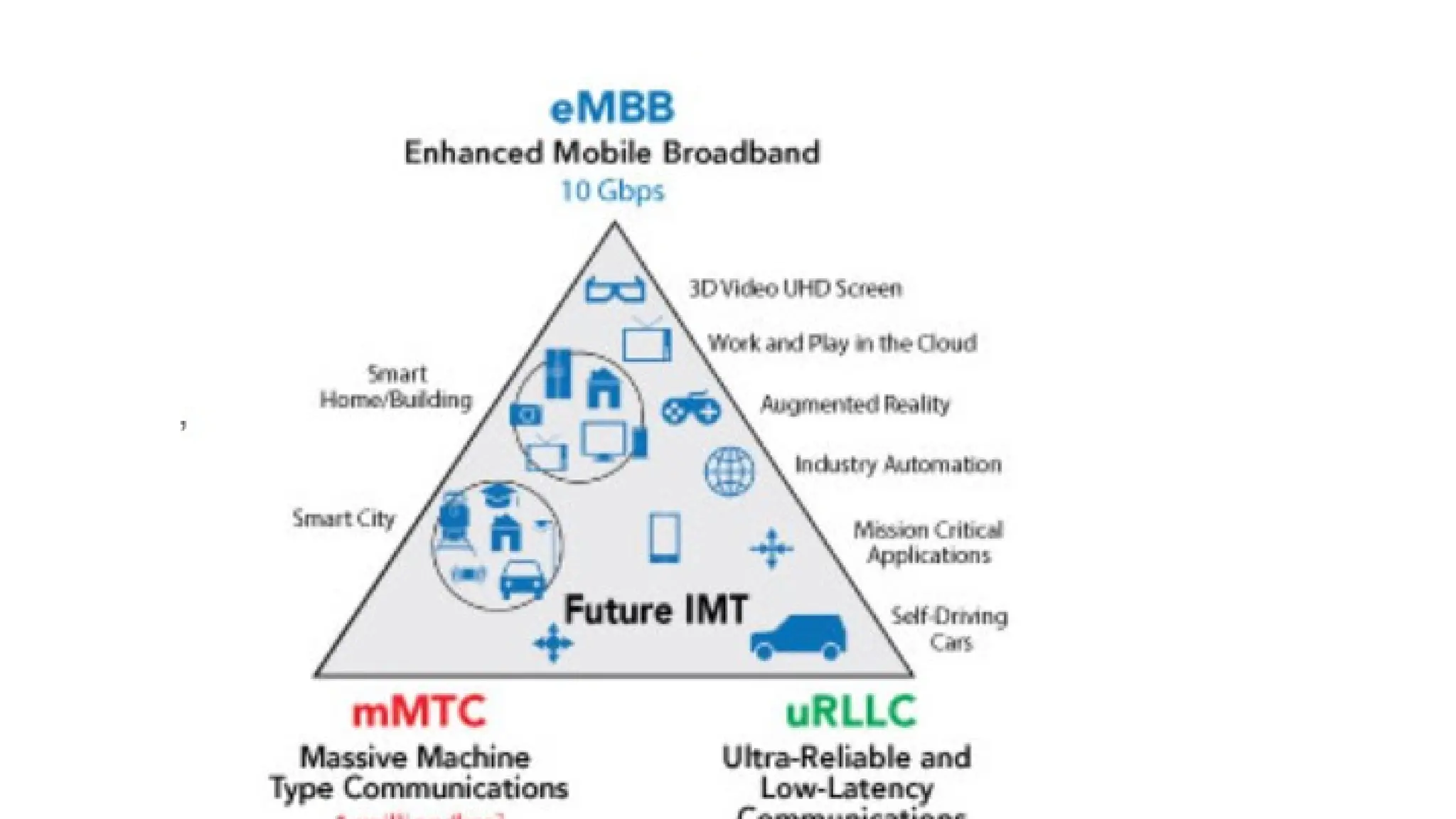
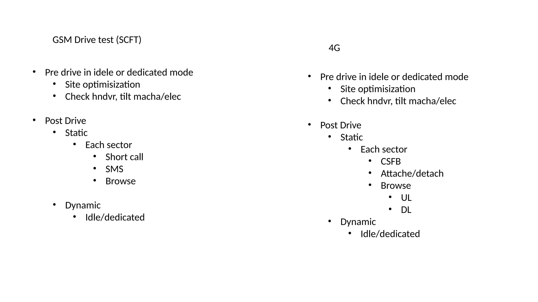
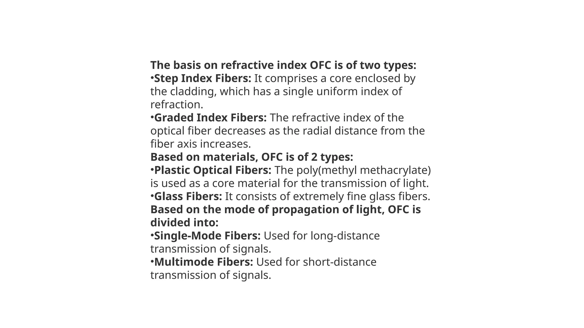
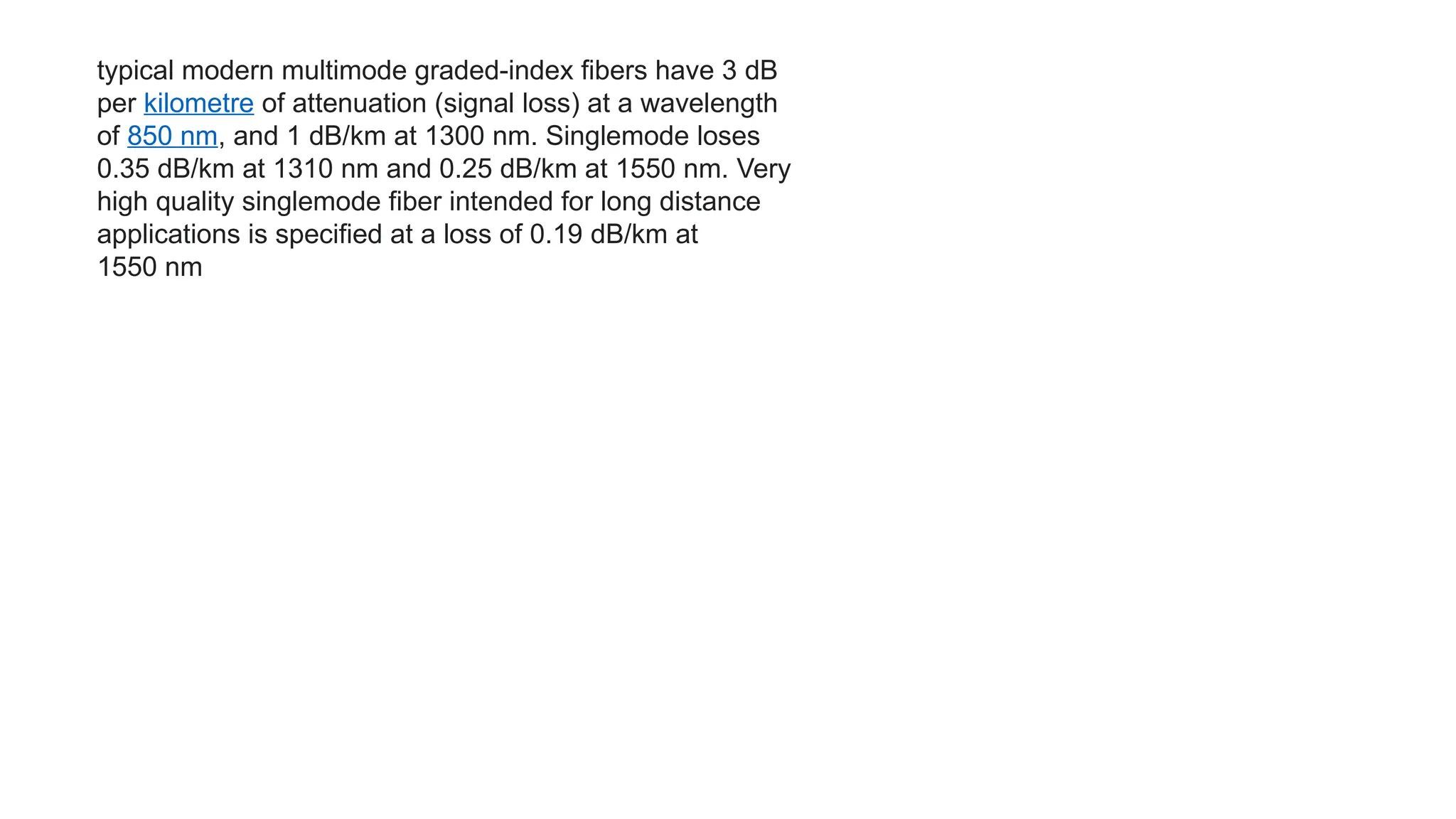
1.4G Architecture
2.4G Attach Call Flow
3.4G Protocol Stack
4.5G Architecture
5.5G Service verticals
6.Open RAN
UE
eNB
eNB
MME HSS
SGW PGW
PCRF OCS
PDN
E UTRAN EPC
Uu/Air Interface
S1-MME
S11
S6A
• Mobility
• Authentication
• Subscriber database
• eNB IP Adresses
• TA database
• Assigning IP to UE
X2
S1-U S5/S8
Gx
Gy
• Policy per subscriber • Charging
UE eNB MME HSS
Random Access Preamble
C-RNTI
RRC Connection Request
RRC Connection Response
Attach Request
PDN Conn Request
Attach Request(IMSI)
PDN Conn Request
NAS
Auth Request(IMSI)
Auth Response
(Kasme, AUTN, RAND) XRES)
Auth Request(AUTN, RAND))
Auth Response
(RES)
Auth Response
(RES)
RRC Setup/
Uplink Synch
UE Authentication
UE eNB MME HSS PGW
Security Mode command
SGW
NAS Security Procedure for
Encryption and data Integrity
Security Mode command
Security Mode complete
Location Update Request
Location Update Response
UE Authorization
Create Session Request
Create Session Response
Create Session Request
GTPU Tunnel between
SGW&PGW
UE eNB MME HSS PGW
Initial Context setup request
Attach Accept
Radio Bearer request
SGW
AS Security
RRC Security mode command
RRC Security mode complete
Initial Context setup complete
Attach complete
DHCP Message
Controlplane Protocol Stack
NAS
RRC
PDCP
RLC
MAC
PHY
RRC S1-AP
PDCP SCTP
RLC IP
MAC L2
PHY L1
NAS
S1-AP GTP-C
SCTP UDP
IP IP
L2 L2
L1 L1
GTP-C GTP-C
UDP UDP
IP IP
L2 L2
L1 L1
GTP-C
UDP
IP
L2
L1
UE eNB MME SGW PGW
Userplane Protocol Stack
Application
TCP/UDP
IP
PDCP
RLC
MAC
PHY
PDCP GTC-U
UDP
RLC IP
MAC L2
PHY L1
GTP-U GTP-U
UDP UDP
IP IP
L2 L2
L1 L1
Application
TCP/UDP
IP
PDCP
RLC
MAC
PHY
UE
eNB SGW PGW
IP
GTP-U GTP-U
UDP UDP
IP IP
L2 L2
L1 L1
End Host
UE gNB
AMF
NSSF NEF NRF UDM AUSF PCF
SMF
UPF
AF
• Mobility mngmt
• Registration
• Connection
• Slice selection for UE
• Exposure of any
element through NEF
• To identify element
with specific function
• User database
• SUPI, SUCI
• Authentication
• Policy control
• IP Allocation to UE
• Session establishment, modify, release
• DHCP client server fn
• Connectivity towards external data NW over user plane
• Connectivity to core NW
applications
5G Architecture
MME
N26
The Physical Layer (PHY): Like LTE, LTE-A uses OFDM technology to cancel the Inter Symbol Interference (ISI).
•
The Medium Access Control (MAC): It performs resource scheduling and Hybrid Automatic Repeat Request (HARQ) for
retransmission.
•
The Radio Link Control (RLC): It manages the delivery of the data. It is responsible for segmentation of data based on Transport
Block Size (TBS).
•
The Packet Data Convergence Protocol (PDCP) does ciphering, retransmission and header compression of user data.
•
The Radio Resource Control (RRC) manages security functions (authentication, and authorization), handling mobility, roaming, and
handovers.
The Non-Access Stratum (NAS) is responsible for authentication, registration, connection/session management between UE and
the core network.
5G Deployment Scenario
4G / 5G – Services
• eMBB – enhanced Mobile Broadband (High throughput application)
• UHD Movie D/L
• AR Video
• VR Video
• Real Time Gaming in AR
• URLLC – Ultra Reliable Low Latency Communication (Low latency apps)
• Remote Surgery
• mMTC – Massive Machine Type Communication (Moderate latency requirement)
• Meter Reading
• Car manufacturing plant
• V2X ((Low latency apps)
• eMBB APN1 eMBB – Entertainment - Movie / Song / Other personalized requirements
• APN2 eMBB - Car Manufacturing back-end (vehicle Telematics),
• APN3 - URLLC – Auto Driven Car – Traffic Signal & Neighboring Car
RAN Evolution
BBU+RU
• More Losses
BBU
• Same vendor for
RU and BBU HW and SW
RU
BBU
RU
RU
• Same BBU serving multiple RU.
• Same vendor for
RU and BBU HW and SW
BBU SW
COTS HW
RU
RU
• Same BBU serving multiple RU.
• Same vendor for
RU(HW+SW) and BBU SW.
C-RAN V-RAN
D-RAN D-RAN
RU
DU
CU-C CU-U
Near RT RIC
Orchestrator
Open Fronthaul
F1-C F1-U
E2 E2
E1
A1 O
Non RT RIC
O1
O1
The Near-RT RIC resides within a telco edge cloud or regional cloud and is responsible for intelligent edge
control of RAN nodes and resources. The Near-RT RIC controls RAN elements and their resources with optimization
actions that typically take 10 milliseconds to one second to complete. It receives policy guidance from the Non-RT RIC
and provides policy feedback to the Non-RT RIC through specialized applications called xApps.
The Non-RT RIC is part of the Service Management and Orchestration (SMO) Framework, centrally deployed in the service
provider network, which enables non-real-time (> 1 second) control of RAN elements and their resources through specialize
applications called rApps. Non-RT RIC communicates with applications called xApps running on a Near-RT RIC to
provide policy-based guidance for edge control of RAN elements and their resources.
Higher functional splits are more desirable for capacity
use cases in dense urban areas while lower functional
splits will be the optimum solutions for coverage use
cases. So, while lower functional splits utilize less than
perfect fronthauls, there is a greater dependence on
fronthaul performance for higher functional splits
5G Numerology
• Unlike LTE which has only 1 subcarrier spacing (15 KHz), 5G NR has several subcarrier spacing
• In LTE, we don’t need any specific terminology to talk about the unique subcarrier spacing but in 5G
NR “Numerology” indicates the “Subcarrier Spacing Type” .
• The support of multiple numerologies and multiple subcarrier spacings is the most outstanding NR feature, when
compared to LTE.
• 5G NR Numerology varies from 0 to 4 indicating different types of Subcarrier spacing from 15 KHz to 240 KHz
• Numerology-4 : 240 kHz sub-carrier spacing can be used to provide broadcast signals at millimeter-wave
• All other Sub-carrier spacing are supported for data and signaling except 60 KHz which is for data Physical
channels only
• Numerologies 0 and 1 (15/30 KHz) can be used only in FR1 (Frequency Range 1 – sub 6 GHz)
• Numerology 3 (120 KHz) can be used only in FR2 (> 24.5 GHz)
• Numerology 2 (60 KHz) can be used in both Frequency ranges FR1 and FR2.
• At high level, we can say that 5G NR have cover a very wide range of frequency e.g, sub 3 Ghz, sub 6 Ghz and
mmWave over 25 Ghz and each frequency range have its own charcterisitics in term of propagation,
doppler, inter sysmbol etc. So, it is hard to support the complete frequency range with single
numerology (SCS) without sacrificing too much of efficiency or performance.
A Bandwidth Part (BWP) is a contiguous set of physical resource blocks (PRBs) on a given
carrier. These RBs are selected from a contiguous subset of the common resource blocks for a
given numerology (u). It is denoted by BWP. Each BWP defined for a numerology can have
following three different parameters.
•Subcarrier spacing
•Symbol duration
•Cyclic prefix (CP) length
•A wider Bandwidth has direct impact on the peak and user experienced data rates, however
users are not always demanding high data rate. The use of wide BW may imply higher idling
power consumption both from RF and baseband signal processing perspectives. In regards to
this , new concept of BWP has been introduced for 5G-NR provides a means of operating UEs
with smaller BW than the configured CBW, which makes NR an energy efficient solution despite
the support of wideband operation.
Bandwidth Parts
Beamforming is used with phased array antennae systems to
focus the wireless signal in a chosen direction, normally towards
a specific receiving device. This results in an improved signal at
the user equipment (UE), and also less interference between the
signals of individual UE.
Phased antenna arrays are designed so that the radiation
patterns from each individual element combine constructively,
with those from neighbouring elements forming an effective
radiation pattern - the main lobe - which transmits energy in the
desired direction.
At the same time, the antenna array is designed so that signals
sent in undesired directions destructively interfere with each
other, forming nulls and side lobes.
The overall antenna array system is designed to maximize the
energy radiated in the main lobe, whilst limiting the energy in the
side lobes to an acceptable level.
The direction of the main lobe, or beam, is controlled by
manipulating the radio signals applied to each of the individual
antenna elements in the array.
Each antenna is fed with the same transmitted signal but the
phase and amplitude of the signal fed to each element is
adjusted, steering the beam in the desired direction (see Figure 2,
left).
Massive MIMO is based upon the three key concepts of spatial
diversity, spatial multiplexing, and beamforming. MIMO builds on
the fact that a radio signal between transmitter and receiver is
filtered by its environment, with reflections from buildings and
other obstacles resulting in multiple signal paths (see Figure 1,
right).
The various reflected signals will arrive at the receiving antenna
with differing time delays, levels of attenuation and direction of
travel. When multiple receive antennas are deployed, each
antenna receives a slightly different version of the signal, which
can be combined mathematically to improve the quality of the
transmitted signal.
This technique is known as spatial diversity since the receiver
antennas are spatially separated from each other. Spatial
diversity is also achieved by transmitting the radio signal over
multiple antennae, with each antenna, in some cases, sending
modified versions of the signal.
Whilst spatial diversity increases the reliability of the radio link,
spatial multiplexing increases the capacity of the radio link by
using the multiple transition paths as additional channels for
carrying data. Spatial multiplexing allows multiple, unique,
streams of data to be sent between the transmitter and receiver,
significantly increasing throughput and also enabling multiple
network users to be supported by a single transmitter, hence the
term MU-MIMO.
LTE Advanced is an enhancement added to LTE to introduce carrier aggregation,
256 QAM and higher-order MIMO (8×8 & 4×4) for improving peak data rates to 1 Gbps
COMP
1) Joint processing
1) Array of antenna
2) Coordinated Scheduling
Single radio voice call continuity (SRVCC) is an LTE feature that allows a VoIP/IMS call in the
LTE packet-switched domain to be transferred to a legacy circuit-switched domain
LTE Physical Layer
OFDMA in Downlink
SC-FDMA in Uplink
GSM Drive test (SCFT)
• Pre drive in idele or dedicated mode
• Site optimisization
• Check hndvr, tilt macha/elec
• Post Drive
• Static
• Each sector
• Short call
• SMS
• Browse
• Dynamic
• Idle/dedicated
• Pre drive in idele or dedicated mode
• Site optimisization
• Check hndvr, tilt macha/elec
• Post Drive
• Static
• Each sector
• CSFB
• Attache/detach
• Browse
• UL
• DL
• Dynamic
• Idle/dedicated
4G
The basis on refractive index OFC is of two types:
•Step Index Fibers: It comprises a core enclosed by
the cladding, which has a single uniform index of
refraction.
•Graded Index Fibers: The refractive index of the
optical fiber decreases as the radial distance from the
fiber axis increases.
Based on materials, OFC is of 2 types:
•Plastic Optical Fibers: The poly(methyl methacrylate)
is used as a core material for the transmission of light.
•Glass Fibers: It consists of extremely fine glass fibers.
Based on the mode of propagation of light, OFC is
divided into:
•Single-Mode Fibers: Used for long-distance
transmission of signals.
•Multimode Fibers: Used for short-distance
transmission of signals.
typical modern multimode graded-index fibers have 3 dB
per kilometre of attenuation (signal loss) at a wavelength
of 850 nm, and 1 dB/km at 1300 nm. Singlemode loses
0.35 dB/km at 1310 nm and 0.25 dB/km at 1550 nm. Very
high quality singlemode fiber intended for long distance
applications is specified at a loss of 0.19 dB/km at
1550 nm
4G technology brief, call flow, 5G architecture

4G technology brief, call flow, 5G architecture

  • 1.
    1.4G Architecture 2.4G AttachCall Flow 3.4G Protocol Stack 4.5G Architecture 5.5G Service verticals 6.Open RAN
  • 2.
    UE eNB eNB MME HSS SGW PGW PCRFOCS PDN E UTRAN EPC Uu/Air Interface S1-MME S11 S6A • Mobility • Authentication • Subscriber database • eNB IP Adresses • TA database • Assigning IP to UE X2 S1-U S5/S8 Gx Gy • Policy per subscriber • Charging
  • 3.
    UE eNB MMEHSS Random Access Preamble C-RNTI RRC Connection Request RRC Connection Response Attach Request PDN Conn Request Attach Request(IMSI) PDN Conn Request NAS Auth Request(IMSI) Auth Response (Kasme, AUTN, RAND) XRES) Auth Request(AUTN, RAND)) Auth Request(AUTN, RAND)) Auth Response (RES) Auth Response (RES) RRC Setup/ Uplink Synch UE Authentication
  • 4.
    UE eNB MMEHSS PGW Security Mode command SGW NAS Security Procedure for Encryption and data Integrity Security Mode command Security Mode complete Security Mode complete Location Update Request Location Update Response UE Authorization Create Session Request Create Session Response Create Session Response Create Session Request GTPU Tunnel between SGW&PGW
  • 5.
    UE eNB MMEHSS PGW Initial Context setup request Attach Accept Radio Bearer request SGW AS Security RRC Security mode command RRC Security mode complete Initial Context setup complete Attach complete DHCP Message
  • 6.
    Controlplane Protocol Stack NAS RRC PDCP RLC MAC PHY RRCS1-AP PDCP SCTP RLC IP MAC L2 PHY L1 NAS S1-AP GTP-C SCTP UDP IP IP L2 L2 L1 L1 GTP-C GTP-C UDP UDP IP IP L2 L2 L1 L1 GTP-C UDP IP L2 L1 UE eNB MME SGW PGW
  • 7.
    Userplane Protocol Stack Application TCP/UDP IP PDCP RLC MAC PHY PDCPGTC-U UDP RLC IP MAC L2 PHY L1 GTP-U GTP-U UDP UDP IP IP L2 L2 L1 L1 Application TCP/UDP IP PDCP RLC MAC PHY UE eNB SGW PGW IP GTP-U GTP-U UDP UDP IP IP L2 L2 L1 L1 End Host
  • 8.
    UE gNB AMF NSSF NEFNRF UDM AUSF PCF SMF UPF AF • Mobility mngmt • Registration • Connection • Slice selection for UE • Exposure of any element through NEF • To identify element with specific function • User database • SUPI, SUCI • Authentication • Policy control • IP Allocation to UE • Session establishment, modify, release • DHCP client server fn • Connectivity towards external data NW over user plane • Connectivity to core NW applications 5G Architecture MME N26
  • 9.
    The Physical Layer(PHY): Like LTE, LTE-A uses OFDM technology to cancel the Inter Symbol Interference (ISI). • The Medium Access Control (MAC): It performs resource scheduling and Hybrid Automatic Repeat Request (HARQ) for retransmission. • The Radio Link Control (RLC): It manages the delivery of the data. It is responsible for segmentation of data based on Transport Block Size (TBS). • The Packet Data Convergence Protocol (PDCP) does ciphering, retransmission and header compression of user data. • The Radio Resource Control (RRC) manages security functions (authentication, and authorization), handling mobility, roaming, and handovers. The Non-Access Stratum (NAS) is responsible for authentication, registration, connection/session management between UE and the core network.
  • 10.
  • 11.
    4G / 5G– Services • eMBB – enhanced Mobile Broadband (High throughput application) • UHD Movie D/L • AR Video • VR Video • Real Time Gaming in AR • URLLC – Ultra Reliable Low Latency Communication (Low latency apps) • Remote Surgery • mMTC – Massive Machine Type Communication (Moderate latency requirement) • Meter Reading • Car manufacturing plant • V2X ((Low latency apps) • eMBB APN1 eMBB – Entertainment - Movie / Song / Other personalized requirements • APN2 eMBB - Car Manufacturing back-end (vehicle Telematics), • APN3 - URLLC – Auto Driven Car – Traffic Signal & Neighboring Car
  • 13.
    RAN Evolution BBU+RU • MoreLosses BBU • Same vendor for RU and BBU HW and SW RU BBU RU RU • Same BBU serving multiple RU. • Same vendor for RU and BBU HW and SW BBU SW COTS HW RU RU • Same BBU serving multiple RU. • Same vendor for RU(HW+SW) and BBU SW. C-RAN V-RAN D-RAN D-RAN
  • 14.
    RU DU CU-C CU-U Near RTRIC Orchestrator Open Fronthaul F1-C F1-U E2 E2 E1 A1 O Non RT RIC O1 O1
  • 15.
    The Near-RT RICresides within a telco edge cloud or regional cloud and is responsible for intelligent edge control of RAN nodes and resources. The Near-RT RIC controls RAN elements and their resources with optimization actions that typically take 10 milliseconds to one second to complete. It receives policy guidance from the Non-RT RIC and provides policy feedback to the Non-RT RIC through specialized applications called xApps. The Non-RT RIC is part of the Service Management and Orchestration (SMO) Framework, centrally deployed in the service provider network, which enables non-real-time (> 1 second) control of RAN elements and their resources through specialize applications called rApps. Non-RT RIC communicates with applications called xApps running on a Near-RT RIC to provide policy-based guidance for edge control of RAN elements and their resources.
  • 16.
    Higher functional splitsare more desirable for capacity use cases in dense urban areas while lower functional splits will be the optimum solutions for coverage use cases. So, while lower functional splits utilize less than perfect fronthauls, there is a greater dependence on fronthaul performance for higher functional splits
  • 17.
    5G Numerology • UnlikeLTE which has only 1 subcarrier spacing (15 KHz), 5G NR has several subcarrier spacing • In LTE, we don’t need any specific terminology to talk about the unique subcarrier spacing but in 5G NR “Numerology” indicates the “Subcarrier Spacing Type” . • The support of multiple numerologies and multiple subcarrier spacings is the most outstanding NR feature, when compared to LTE. • 5G NR Numerology varies from 0 to 4 indicating different types of Subcarrier spacing from 15 KHz to 240 KHz • Numerology-4 : 240 kHz sub-carrier spacing can be used to provide broadcast signals at millimeter-wave • All other Sub-carrier spacing are supported for data and signaling except 60 KHz which is for data Physical channels only • Numerologies 0 and 1 (15/30 KHz) can be used only in FR1 (Frequency Range 1 – sub 6 GHz) • Numerology 3 (120 KHz) can be used only in FR2 (> 24.5 GHz) • Numerology 2 (60 KHz) can be used in both Frequency ranges FR1 and FR2. • At high level, we can say that 5G NR have cover a very wide range of frequency e.g, sub 3 Ghz, sub 6 Ghz and mmWave over 25 Ghz and each frequency range have its own charcterisitics in term of propagation, doppler, inter sysmbol etc. So, it is hard to support the complete frequency range with single numerology (SCS) without sacrificing too much of efficiency or performance.
  • 18.
    A Bandwidth Part(BWP) is a contiguous set of physical resource blocks (PRBs) on a given carrier. These RBs are selected from a contiguous subset of the common resource blocks for a given numerology (u). It is denoted by BWP. Each BWP defined for a numerology can have following three different parameters. •Subcarrier spacing •Symbol duration •Cyclic prefix (CP) length •A wider Bandwidth has direct impact on the peak and user experienced data rates, however users are not always demanding high data rate. The use of wide BW may imply higher idling power consumption both from RF and baseband signal processing perspectives. In regards to this , new concept of BWP has been introduced for 5G-NR provides a means of operating UEs with smaller BW than the configured CBW, which makes NR an energy efficient solution despite the support of wideband operation. Bandwidth Parts
  • 19.
    Beamforming is usedwith phased array antennae systems to focus the wireless signal in a chosen direction, normally towards a specific receiving device. This results in an improved signal at the user equipment (UE), and also less interference between the signals of individual UE. Phased antenna arrays are designed so that the radiation patterns from each individual element combine constructively, with those from neighbouring elements forming an effective radiation pattern - the main lobe - which transmits energy in the desired direction. At the same time, the antenna array is designed so that signals sent in undesired directions destructively interfere with each other, forming nulls and side lobes. The overall antenna array system is designed to maximize the energy radiated in the main lobe, whilst limiting the energy in the side lobes to an acceptable level. The direction of the main lobe, or beam, is controlled by manipulating the radio signals applied to each of the individual antenna elements in the array. Each antenna is fed with the same transmitted signal but the phase and amplitude of the signal fed to each element is adjusted, steering the beam in the desired direction (see Figure 2, left).
  • 20.
    Massive MIMO isbased upon the three key concepts of spatial diversity, spatial multiplexing, and beamforming. MIMO builds on the fact that a radio signal between transmitter and receiver is filtered by its environment, with reflections from buildings and other obstacles resulting in multiple signal paths (see Figure 1, right). The various reflected signals will arrive at the receiving antenna with differing time delays, levels of attenuation and direction of travel. When multiple receive antennas are deployed, each antenna receives a slightly different version of the signal, which can be combined mathematically to improve the quality of the transmitted signal. This technique is known as spatial diversity since the receiver antennas are spatially separated from each other. Spatial diversity is also achieved by transmitting the radio signal over multiple antennae, with each antenna, in some cases, sending modified versions of the signal. Whilst spatial diversity increases the reliability of the radio link, spatial multiplexing increases the capacity of the radio link by using the multiple transition paths as additional channels for carrying data. Spatial multiplexing allows multiple, unique, streams of data to be sent between the transmitter and receiver, significantly increasing throughput and also enabling multiple network users to be supported by a single transmitter, hence the term MU-MIMO.
  • 22.
    LTE Advanced isan enhancement added to LTE to introduce carrier aggregation, 256 QAM and higher-order MIMO (8×8 & 4×4) for improving peak data rates to 1 Gbps
  • 25.
    COMP 1) Joint processing 1)Array of antenna 2) Coordinated Scheduling
  • 26.
    Single radio voicecall continuity (SRVCC) is an LTE feature that allows a VoIP/IMS call in the LTE packet-switched domain to be transferred to a legacy circuit-switched domain
  • 27.
    LTE Physical Layer OFDMAin Downlink SC-FDMA in Uplink
  • 29.
    GSM Drive test(SCFT) • Pre drive in idele or dedicated mode • Site optimisization • Check hndvr, tilt macha/elec • Post Drive • Static • Each sector • Short call • SMS • Browse • Dynamic • Idle/dedicated • Pre drive in idele or dedicated mode • Site optimisization • Check hndvr, tilt macha/elec • Post Drive • Static • Each sector • CSFB • Attache/detach • Browse • UL • DL • Dynamic • Idle/dedicated 4G
  • 30.
    The basis onrefractive index OFC is of two types: •Step Index Fibers: It comprises a core enclosed by the cladding, which has a single uniform index of refraction. •Graded Index Fibers: The refractive index of the optical fiber decreases as the radial distance from the fiber axis increases. Based on materials, OFC is of 2 types: •Plastic Optical Fibers: The poly(methyl methacrylate) is used as a core material for the transmission of light. •Glass Fibers: It consists of extremely fine glass fibers. Based on the mode of propagation of light, OFC is divided into: •Single-Mode Fibers: Used for long-distance transmission of signals. •Multimode Fibers: Used for short-distance transmission of signals.
  • 31.
    typical modern multimodegraded-index fibers have 3 dB per kilometre of attenuation (signal loss) at a wavelength of 850 nm, and 1 dB/km at 1300 nm. Singlemode loses 0.35 dB/km at 1310 nm and 0.25 dB/km at 1550 nm. Very high quality singlemode fiber intended for long distance applications is specified at a loss of 0.19 dB/km at 1550 nm