Downloaded 158 times

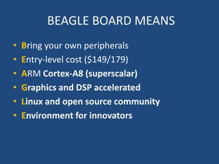
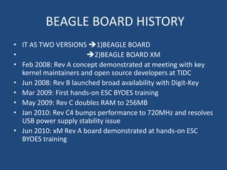


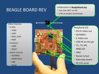


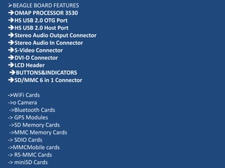


The document provides an overview of the BeagleBoard, including: - It has two versions, the original BeagleBoard and the BeagleBoard XM. - It is based around the OMAP3530 processor and has various I/O including USB, audio, video, and expansion interfaces. - It runs Linux and has an active open source developer community for creating innovative projects.