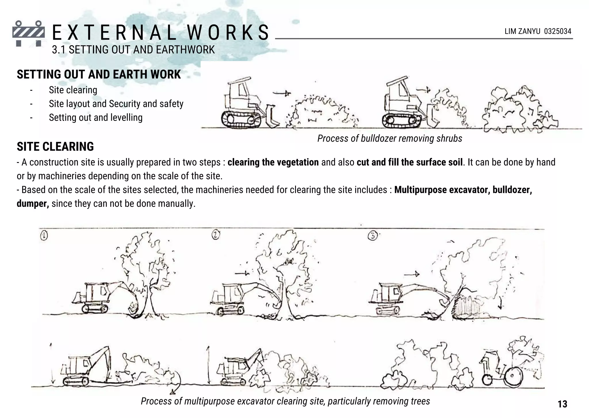
1. Site clearing involves removing vegetation from the construction site using machinery like excavators and bulldozers. Soil filling then levels the ground by cutting and filling soil.
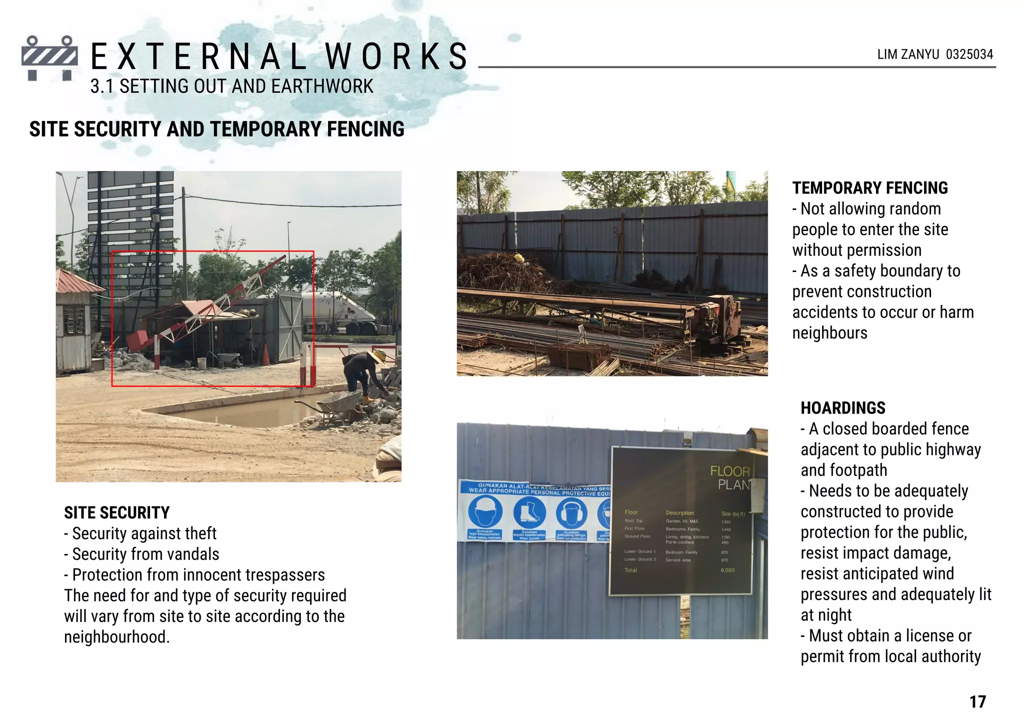
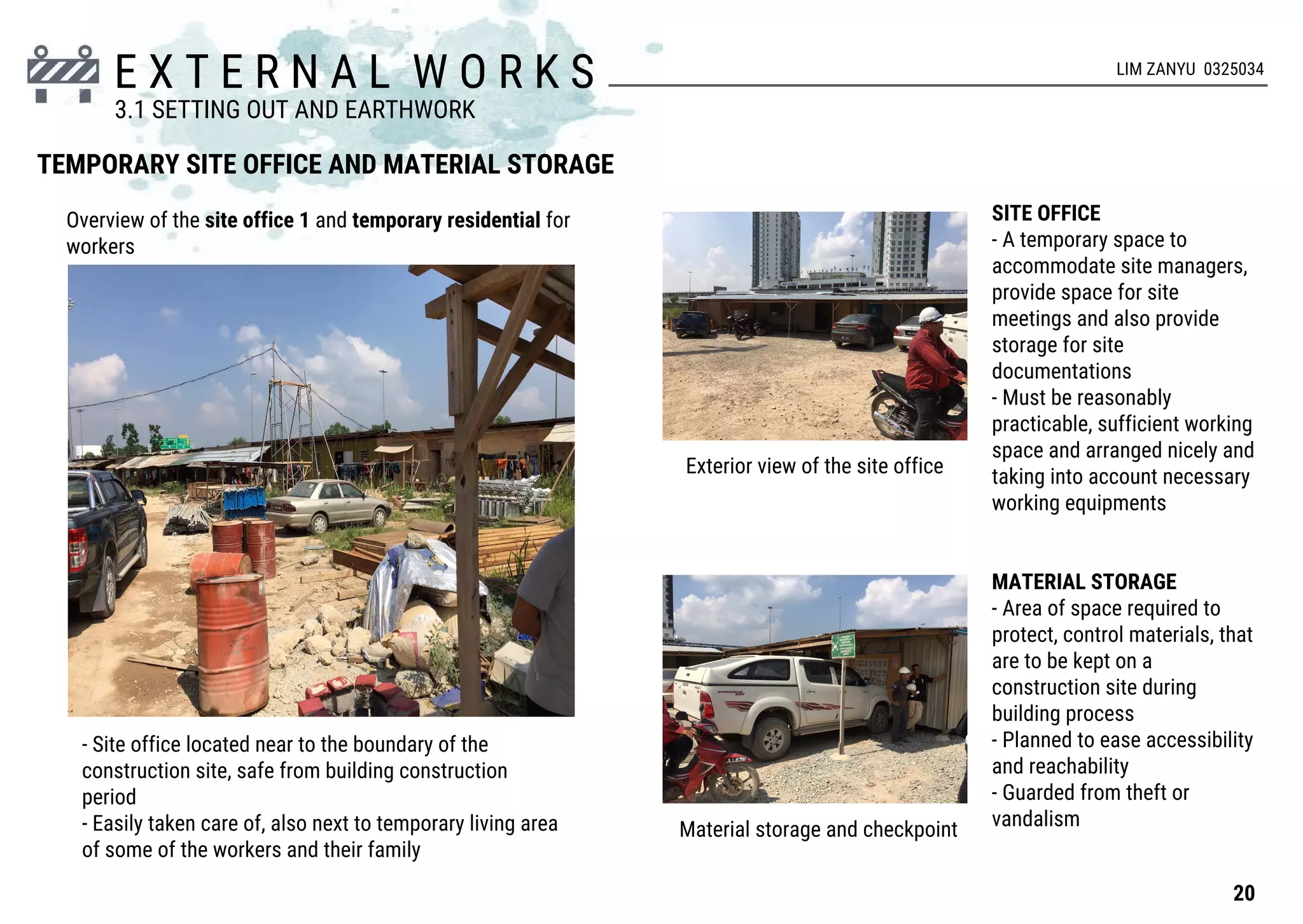
2. Site layout includes temporary site facilities like offices, storage, and toilets. Retaining walls are built for sloped sites to prevent erosion. Fencing secures the boundary.
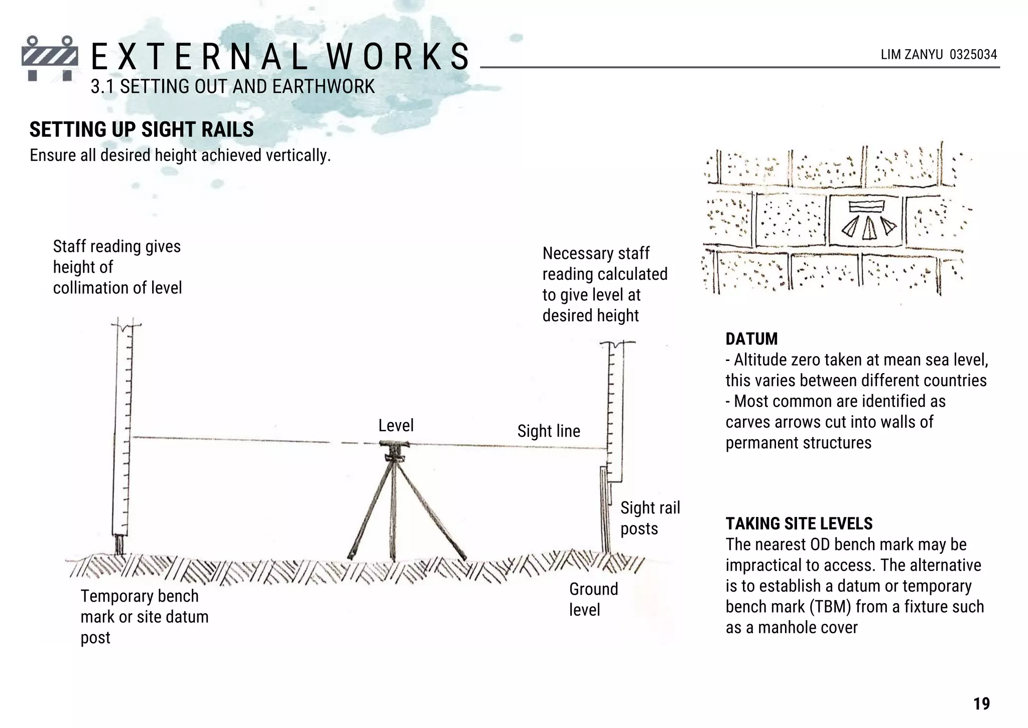
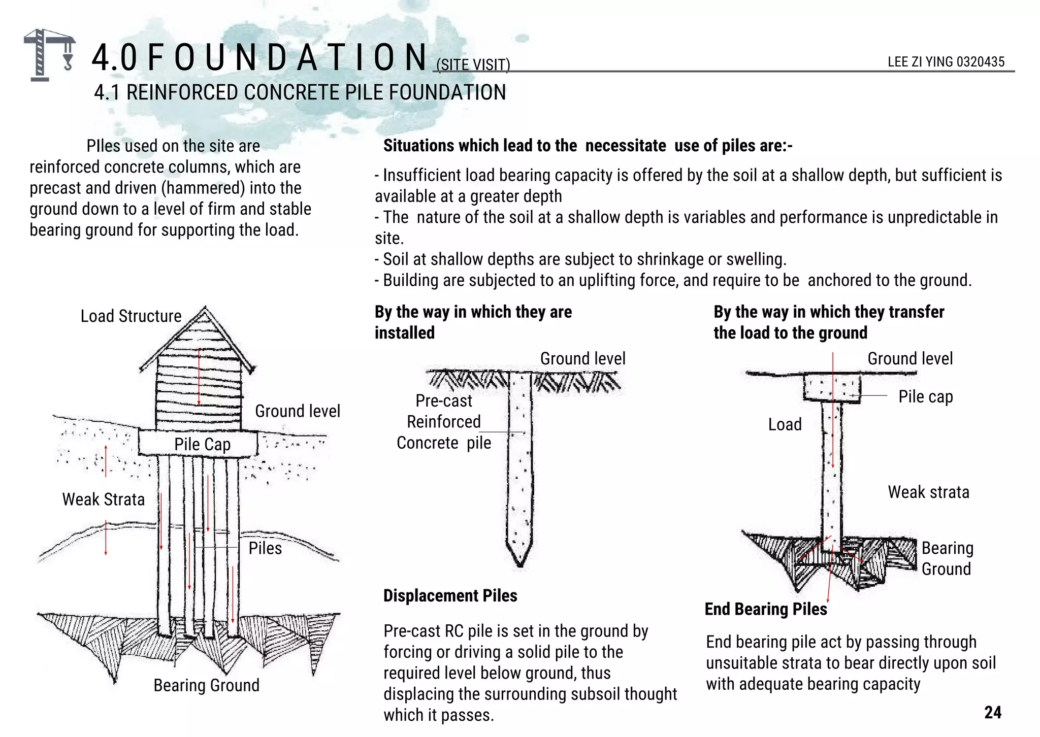
3. Setting out establishes horizontal and vertical control points to lay the foundations and guide subsequent construction stages according to the building plans.
Project 1: Industrialised Building System [ IBS ]JerotichMaswan
Project 1 of Advanced Architectural Construction.
Requirement: Design a 3 storey apartment building using Precast Concrete System. Other IBS systems are allowed. Create a report on IBS and the building detailing.
Project 1: Industrialised Building System [ IBS ]JerotichMaswan
Project 1 of Advanced Architectural Construction.
Requirement: Design a 3 storey apartment building using Precast Concrete System. Other IBS systems are allowed. Create a report on IBS and the building detailing.
Contract implementation and management phase in Malaysia Construction PracticeZhao Wei Kim
A brief layout of the contract implementation and management phase's components. The components are to be well versed within the consultancy service firms and contractors.
This presentation deals with the capacity of Fire Escapes, no. of fire escapes required in a building and the different Fire Escape system along with their functionality...
Most construction sites that run into trouble do so for reasons related to managerial factors rather than because of technical problems. The site-based management can make significant improvements in the cost and time savings during the construction process without involving a mass of additional work. The role of site managers is to control and maintain work performance and then taking actions to rectify situations where performance is unsatisfactory.
Concepts and Formulas of Construction Site Layout Planning Elements:
A well-planned site including all temporary facilities and utilities lead to: 1) increasing productivity and safety, 2) reducing area(s) needed for temporary construction, and 3) maximizing utilization. The following points should be considered in good site layout
Site layout planning can affect productivity and is crucial to project success. However, as construction is heterogeneous in the nature of its organizations, project designs, time constraints, environmental effects, etc., site layout planning for each project becomes unique. Affected by many uncertainties variables! And variations, site layout planning is a typical multi objective problem.
Problem solving requires representing the problem in a language that problem solvers can understand. However, solutions of most construction problems rely on empirical Knowledge about the site layout that can be as a site space allocation for material storage, working areas, units of accommodation, plant positions, general circulation areas, and also access and egress for deliveries and emergency services. Furthermore, conflicting objectives and the uniqueness of construction projects like bad site layout make the problems difficult to conceptualize and define.
A report on the procedures and construction process of buildings based on real life site visits at Taman Bukit Segar, Cheras and Glenmarie Cove, Klang.
By students of Bsc(Hons) Architecture of Taylor's University.
Taylor's University Lakeside Campus
School of Architecture, Building & Design
Bachelor of Science (Hons) in Architecture
Architecture Design Project (ARC 60108)
Conventional Indian construction industry has been forced to look for technology to address its demand & supply gap, diminishing skilled labour and stringent time frame.
Precast concrete construction methodology fits perfectly as an alternative for traditional construction with shorter construction duration and reduction in labor, while exceeding quality standards of conventional construction practices in India.
The success of this technology fully depends on the Architects, the Structural engineers and the Execution team who are willing to adapt this change from convention method of construction to the precast construction. Change gives us a lot of opportunity to adapt, innovate and implement new efficient technology which will be beneficial to the society at large margin.
This technology is becoming trend due to its huge advantages. But in recent past hazards attended to such construction due to collapse. So from the Structural Engineering point of view we have to design keeping in mind the structural safety against this type of collapse.
Hello everyone! I am thrilled to present my latest portfolio on LinkedIn, marking the culmination of my architectural journey thus far. Over the span of five years, I've been fortunate to acquire a wealth of knowledge under the guidance of esteemed professors and industry mentors. From rigorous academic pursuits to practical engagements, each experience has contributed to my growth and refinement as an architecture student. This portfolio not only showcases my projects but also underscores my attention to detail and to innovative architecture as a profession.
Expert Accessory Dwelling Unit (ADU) Drafting ServicesResDraft
Whether you’re looking to create a guest house, a rental unit, or a private retreat, our experienced team will design a space that complements your existing home and maximizes your investment. We provide personalized, comprehensive expert accessory dwelling unit (ADU)drafting solutions tailored to your needs, ensuring a seamless process from concept to completion.
Book Formatting: Quality Control Checks for DesignersConfidence Ago
This presentation was made to help designers who work in publishing houses or format books for printing ensure quality.
Quality control is vital to every industry. This is why every department in a company need create a method they use in ensuring quality. This, perhaps, will not only improve the quality of products and bring errors to the barest minimum, but take it to a near perfect finish.
It is beyond a moot point that a good book will somewhat be judged by its cover, but the content of the book remains king. No matter how beautiful the cover, if the quality of writing or presentation is off, that will be a reason for readers not to come back to the book or recommend it.
So, this presentation points designers to some important things that may be missed by an editor that they could eventually discover and call the attention of the editor.
You could be a professional graphic designer and still make mistakes. There is always the possibility of human error. On the other hand if you’re not a designer, the chances of making some common graphic design mistakes are even higher. Because you don’t know what you don’t know. That’s where this blog comes in. To make your job easier and help you create better designs, we have put together a list of common graphic design mistakes that you need to avoid.
1. BUILDING CONSTRUCTION I (BLD 60303)
PROJECT 01: EXPERIENCING CONSTRUCTION
ASSIGNMENT 1: EXPERIENCING, DOCUMENT AND ANALYSIS CONSTRUCTION PROCESS
ANG AVERLLEN 0321444 | ONG SHI HUI 0320303 | NG WYN JANE 0319440 | LIM ZIA HUEI 0321031
JACK LEE 0325810 | LEE ZI YING 0320435 | LIM ZANYU 0325034 | LIM YANG KANG 0320538
2. C O N T E N T
1.0 INTRODUCTION
1.1 INTRODUCTION OF SITE
2.0 SITE AND SAFETY
2.1 PLANTS AND MACHINERY
3.0 EXTERNAL WORK
3.1 SETTING OUT AND EARTHWORK
4.0 FOUNDATION
4.1 REINFORCED CONCRETE PILE FOUNDATION
4.2 REINFORCED CONCRETE PILE CAP
4.3 COLUMN STUMP FORMATION
4.4 SHALLOW FOUNDATION
5.0 BASEMENT
5.1 BASEMENT CONSTRUCTION
5.2 RETAINING WALL
6.0 SUPERSTRUCTURE
6.1 COLUMNS
6.2 BEAMS
6.3 SLABS
6.4 WALLS
6.5 STAIRCASES
7.0 DOORS AND WINDOWS
7.1 DOORS
7.2 WINDOWS
8.0 ROOF
9.0 SUMMARY
10.0 REFERENCES
3. I N T R O D U C T I O N
First site visit
BSP VILLAGE COMMERCIAL CENTRE
Second site visit
KELAB UKAY RESIDENCE
1.1 INTRODUCTION TO THE SITE
01
4. I N T R O D U C T I O N
BSP VILLAGE COMMERCIAL CENTER
Jalan Saujana Putra, Bandar Saujana Putra, Jenjarom, 42610,
Selangor
Land Acres: 16 Acres
Total Units: 164 Units
Project Type: 2 & 3 storey shop office
Gross built-up: 2 storey (from 2,761 sq.ft.), 3 storey (from 4,425
sq.ft.)
Layout: 22’ x 70’ ; 22’ x 80’
Accessibility: Can be accessible via 4 major highways
(Elite, Skve, Kesas & LDP)
1.1 INTRODUCTION TO THE SITE
-Multi-storey shopping mall
-Extensive food and beverage choices
-Friendly environment pedestrian walk street
-Ample parking
-Innovative lifestyle zones
-Dedicated entertainment zones.
-Open air plazas and courtyards.
-Supermarket street bazaars.
Located at the vibrant
heart of Bandar
Saujana Putra in
Puchong, Selangor.
02
5. I N T R O D U C T I O N
BSP VILLAGE COMMERCIAL CENTER - FLOOR PLAN
1.1 INTRODUCTION TO THE SITE
2 STOREY SHOP OFFICE
(22’ X 70’)
2 STOREY SHOP OFFICE - INTERMEDIATE LOT
(22’ X 80’)
GROUND FLOOR FIRST FLOORFIRST FLOOR GROUND FLOOR
03
6. I N T R O D U C T I O N
Jalan Kelab Ukay 2, 68000 Ampang, Selangor, Malaysia.
Land Acres: 0.75 Acres
Total Units: 15 Units
Project Type: 5 storey superlink house (3+1+1 storey with roof top garden)
To Batu Caves
To Cheras
To Duta
To KLCC
To Setapak
To KLCC
1.1 INTRODUCTION TO THE SITE
KELAB UKAY RESIDENCE
-Located within an upscale and mature residential area.
-Impressive exterior with a blend of modern linear design and floor-to-ceiling glass panels.
-Unobstructed mountain view that extends to the living area and master bedrooms.
-Cool breeze air from the greenery surroundings.
-Within a 24-hour guarded community.
-Easily accessible to Kuala Lumpur and Petaling Jaya via major highway networks.
-Easy access to complete basic and support functions
-6.000sf contemporary home with private lift leading to all levels.
-30 feet setback in each unit to provide ample parking space for 4 cars at the drive way.
04
7. I N T R O D U C T I O N
ROOF TOP
The 800-square-feet roof
top garden providing
excellent views of the
surroundings
KELAB UKAY RESIDENCE - FLOOR PLANS
1ST FLOOR
En-suite master
bedroom 1, 2 en-suite
bedrooms
LOWER GROUND 1
En-suite bedroom 2 and
family hall
GROUND FLOOR
Car porch for 4 cars, a
spacious living area,
dining room, wet and dry
kitchen
LOWER GROUND 2
A large service area
that offers the
convenience of laundry
and storage space
1.1 INTRODUCTION TO THE SITE
05
8. S I T E & S A F E T Y
The construction industry has long been considered as a difficult, dangerous and dirty occupation due to the high number of accidents,
injuries and deaths. Construction workers are exposed to different rinks. Example: falling from heights, movement of the plant and
machinery, electrical shocks, drowning, excessive noise and etc.
SIGNAGES
The reason of placing safety sign is to deliver
the important of the information to public and
warn the public about hazard that could be
happen in construction site. No only that, the
sign provides information of who is working
and the contact as well.
PROHIBITION /
DANGER
ALARM
WARNING
MANDATORY
FIREFIGHTING
NO DANGER
Different colours and symbols of signages give
identify different actions or procedures to be
used.
SIGNAGES FOUND ON SITE
The safety signages showed and informed that
before entry the construction site, everyone have to
wear appropriate personal protective equipments.
Warn drivers about the construction site
ahead.
2.0 SITE AND SAFETY
06
LIM YANG KANG 0320538
9. S I T E & S A F E T Y LIM YANG KANG 0320538
PERSONAL PROTECTIVE EQUIPMENT
Personal protective equipment is clothing and equipment designed to be worn by workers to protect them from injuries. It is a must for
workers to wear PPE all the time on site. Fine will be given to those who don’t abide the rules.
EYE PROTECTION
Safety goggles protect against eye injuries while
workers weld or cut materials & against dust or other
eye irritants.
SAFETY HELMET
Protect the individuals from injuries caused by falling
objects.
EAR PROTECTION
Ear plugs should be worn to protect the ears from
damage especially when it is near or using loud
machinery.
HAND PROTECTION
Gloves is a must protect a worker’s hands from
splinters and other sharp objects.
FOOT PROTECTION
Closed toe shoes only. Work boots are preferred
but thick soled tennis shoes will be allowed.
ATTIRE
-Long sleeve, short sleeve shirts and t-
shirt are allowed
-tight fitting or suggestive is not
allowed.
-must not be exposed in the torso area.
ATTIRE
-Pants and shorts must not be
tight fitting.
-Shorts must be no higher than
mid-thigh.
07
2.0 SITE AND SAFETY
10. S I T E & S A F E T Y
SCAFFOLDING
Scaffolding is a temporary structures that used to support
people and hold materials that are to be used for
construction or repair of buildings and other structures.
They aid safety of the workmen and allow access to areas
that are difficult to reach. They are constructed by using
metal tubes with metal platforms or with bamboos and
wooden planks.
DIAGONAL
BRACE
SILL
BEARER
RUNNER
PLANKING
SAFETY NET
A kind of falling protection system that protect workers from falling
by covering the edge of the building especially when the building are
to be construction up to the height that may cause falling if
precautions are not taken by the workers.
DIAMOND
MESH
Anchor securely to eliminate friction wear and prevent enlargement.
Maximum size of mesh opening less than 6 inches
Safety nets should be used when work
place is more than 25 feet above ground
where the use of scaffolds are impractical.JOINT CONNECTIONS VARY
ACCORDING TO
MANUFACTURER
2.0 SITE AND SAFETY
LIM YANG KANG 0320538
08
11. Excavator is the machine that can excavate the soil of
various types forcefully and then using hydraulic
system a hydraulic force is generated and utilizing
this force bucket is pull back towards the machine.
Bucket of excavator is replaceable. If front bucket is
exchange with some other attachments then
excavator can be used for multi-purpose. For
example: pile diver, hydraulic jack hammer etc…
CRAWLER
EXCAVATOR
-Two endless tracks.
-used in hilly areas where
risks of sliding of machinery
are on the verge.
-Low ground pressure
because of spreading of load
on large area and also used
where soil support is weak.
THE ARM
-Consists of a bucket and a boom.
-Can be replaced by hammer or
breaker.
-Does the digging work.
THE CAB
-The driver’s seat consists
of the control systems and
steering
THE SWING
-Ability to turn
360 degree.
THE FEET
-Two types of excavators bases.
-Wheel excavator use on hard
surface.
-Crawler excavator use on unstable
surface.
S I T E & S A F E T Y
EXCAVATOR
2.1 PLANTS AND MACHINERY
09
LIM YANG KANG 0320538
12. S I T E & S A F E T Y
MOBILE CRANES
A mobile crane is a cable-controlled crane mounted
on crawlers or rubber-tired carriers or a hydraulic-
powered crane with a telescoping boom mounted on
truck-type carriers or as self-propelled models.They
are designed to easily transport to a site and use with
different types of load and cargo with little or no
setup or assembly.
WORK BASED ON SIMPLE
CONCEPT
-Transmission of forces from
point to point through a fluid. -
Two pistons fit into glass
cylinders filled with oil and
connected to another.If
downward forces apply to one
piston, then the force is
transmitted to the second
piston through the oil in the
pile.
THE BOOM
-It is the most recognizable part of the crane. Does
heavy lifting of materials such as beam and
column.
THE JIB
-This lattice like structure
frees up the boom to extend
fully and provide maximum lift
range.
THE COUNTERWEIGHTS
-Keep cranes from
becoming unbalanced
while hoisting heavy
loads.
2.1 PLANTS AND MACHINERY
10
LIM YANG KANG 0320538
13. S I T E & S A F E T Y
BACKHOE-LOADER
The backhoe loader is an engineering and excavation
vehicle that consists of a tractor, front shovel and bucket
and a small backhoe in the rear end. Due to the small size
and versatility, backhoe loaders are common with small
construction projects and excavation type work.
LOADER
A loader is a heavy equipment machine used in construction to move
aside or load materials such as asphalt, demolition debris, dirt, feed,
gravel, logs, raw minerals, recycled material, rock, sand, etc. into or
onto another type of machinery.
THE BOOM
-Bent upwards to make
it easier to dig.
THE BACKHOE
-Use to dig up hard compact
material or lift heavy loads.
THE TRACTOR
-Move easily over all
kind of rough terrain by
controlling the steering
in the cab.
THE LOAD
-Use to pick up and push
large amount of loose
materials into holes.
THE CAB
-Driver’s seat consists of the
control systems and steering.
THE BUCKET
-Use to load materials.
-Can be replace by other devices and tools.
-Different size of buckets.
2.1 PLANTS AND MACHINERY
11
LIM YANG KANG 0320538
14. S I T E & S A F E T Y
CONCRETE MIXER TRUCK
The concrete mixer is a device that homogeneously
combines cement, aggregate such as sand or gravel,
and water to form concrete. A typical concrete mixer
uses a revolving drum to mix the components. For
smaller volume works portable concrete mixers are
often used so that the concrete can be made at the
construction site, giving the workers ample time to use
the concrete before it hardens.
Standard environmental air
pollution prevention device
to be relocated.
Concrete mixing chamber.
Control system
BRACKET
ROLLER
STEPS OF THE CONCRETE MIXER TRUCK WORK
CONCRETE COMPRESSOR PUMP
Pump wet concrete safely through
a delivery system if pipes and
hoses within its published rating
and specification. Stability of the
concrete pump during operation is
provided for the outriggers and
front jack controls for the
outriggers are located on the sides
of the concrete pump.
2.1 PLANTS AND MACHINERY
12
LIM YANG KANG 0320538
15. E X T E R N A L W O R K S
SETTING OUT AND EARTH WORK
- Site clearing
- Site layout and Security and safety
- Setting out and levelling
SITE CLEARING
- A construction site is usually prepared in two steps : clearing the vegetation and also cut and fill the surface soil. It can be done by hand
or by machineries depending on the scale of the site.
- Based on the scale of the sites selected, the machineries needed for clearing the site includes : Multipurpose excavator, bulldozer,
dumper, since they can not be done manually.
Process of bulldozer removing shrubs
Process of multipurpose excavator clearing site, particularly removing trees
LIM ZANYU 0325034
13
3.1 SETTING OUT AND EARTHWORK
16. E X T E R N A L W O R K S
SOIL FILLING
After all the vegetations are removed from site, it will be followed by the process of soil filling, which basically cuts and fill the topmost
surface of the soil, to produce an even surface for the site. The fill dirt used is usually the subsoil and underlying soil parent material which
has little soil organic matter or biological activity. They are taken from a location where soil is being removed as a part of leveling an area for
construction, while it may also contain sand, rocks, and stones, as well as earth.
The other site was built on slope (2 floor
basement and 3 floor above ground floor). Soil
investigation plays a much more important
part in this site, as it helps to reduce the risk of
erosion and land massing. More work is done
to prevent accidents from happening, such as
the construction of retention walls and deeper
piling for foundation.
Cut and fill the soil Even ground levelDifferent in level of soil
RETAINING WALL
- To hold the soil
together
- Prevent the
happening of erosion
to disrupt the
construction progress
A deeper foundation
compared to a normal
construction site
14
3.1 SETTING OUT AND EARTHWORK
LIM ZANYU 0325034
17. E X T E R N A L W O R K S
SITE LAYOUT 1 AND SITE SECURITY
- Temporary site office
- Temporary residential area for workers
- Temporary material storage
- Temporary toilet
- Temporary toilet for workers
- Retention pond
- Construction area
- Site boundary and temporary fencing- Site security
- Entrance to site
15
3.1 SETTING OUT AND EARTHWORK
LIM ZANYU 0325034
18. E X T E R N A L W O R K S
SITE LAYOUT 2 AND SITE SECURITY
- Temporary site office
- Temporary toilet
- Temporary material storage
- Temporary drainage
system
- Construction area
- Temporary electricity supply
- Water trough
- Site boundary and
temporary fencing
- Site security
16
3.1 SETTING OUT AND EARTHWORK
LIM ZANYU 0325034
19. E X T E R N A L W O R K S
SITE SECURITY AND TEMPORARY FENCING
SITE SECURITY
- Security against theft
- Security from vandals
- Protection from innocent trespassers
The need for and type of security required
will vary from site to site according to the
neighbourhood.
TEMPORARY FENCING
- Not allowing random
people to enter the site
without permission
- As a safety boundary to
prevent construction
accidents to occur or harm
neighbours
HOARDINGS
- A closed boarded fence
adjacent to public highway
and footpath
- Needs to be adequately
constructed to provide
protection for the public,
resist impact damage,
resist anticipated wind
pressures and adequately lit
at night
- Must obtain a license or
permit from local authority
17
3.1 SETTING OUT AND EARTHWORK
LIM ZANYU 0325034
20. E X T E R N A L W O R K S
SITE SETTING OUT AND LEVELLING
This task is usually undertaken once the site has been cleared of any obstruction and any reduced-level excavation work is finished. The first
task is to establish a baseline to which all the setting out can be related.
Footpath
Corner post
Site
boundary
Temporary
bench mark or
site datum post
Alternative
method for
corner
SETTING OUT - 3:4:5 METHOD
Using pythagoras theorem
- Calculate the distance from
the first peg to the second (A)
- Lay out the distance from first
peg to third peg (B)
- Using formula :
A² + B² = C²
- The square root of C² will give
an answer and secure a 90 °
Nail in
centre of
post
Cord marking
outline of
building
TEMPORARY BENCH MARK
This is a fixed point on site to
which all levels are related and
should be established at an early
stage in the contract.
Where possible it should relate to
an ordnance bench mark
On site it can be any permanent
feature such as a drain cover or a
firmly driven post
C
18
3.1 SETTING OUT AND EARTHWORK
LIM ZANYU 0325034
21. E X T E R N A L W O R K S
Sight line
Temporary bench
mark or site datum
post
Ground
level
Necessary staff
reading calculated
to give level at
desired height
Staff reading gives
height of
collimation of level
Sight rail
posts
SETTING UP SIGHT RAILS
Level
DATUM
- Altitude zero taken at mean sea level,
this varies between different countries
- Most common are identified as
carves arrows cut into walls of
permanent structures
TAKING SITE LEVELS
The nearest OD bench mark may be
impractical to access. The alternative
is to establish a datum or temporary
bench mark (TBM) from a fixture such
as a manhole cover
19
3.1 SETTING OUT AND EARTHWORK
LIM ZANYU 0325034
Ensure all desired height achieved vertically.
22. E X T E R N A L W O R K S
TEMPORARY SITE OFFICE AND MATERIAL STORAGE
Exterior view of the site office
Material storage and checkpoint
SITE OFFICE
- A temporary space to
accommodate site managers,
provide space for site
meetings and also provide
storage for site
documentations
- Must be reasonably
practicable, sufficient working
space and arranged nicely and
taking into account necessary
working equipments
MATERIAL STORAGE
- Area of space required to
protect, control materials, that
are to be kept on a
construction site during
building process
- Planned to ease accessibility
and reachability
- Guarded from theft or
vandalism
- Site office located near to the boundary of the
construction site, safe from building construction
period
- Easily taken care of, also next to temporary living area
of some of the workers and their family
Overview of the site office 1 and temporary residential for
workers
20
3.1 SETTING OUT AND EARTHWORK
LIM ZANYU 0325034
23. E X T E R N A L W O R K S
Interior view of the site office TEMPORARY TOILET
Exterior view of the site office 2
- Located at an easy accessible place,
preferable near site office
- Kept clean at all time to prevent
mosquitoes or causes uneasy smell
Location of site office 2
21
3.1 SETTING OUT AND EARTHWORK
LIM ZANYU 0325034
24. E X T E R N A L W O R K S
TEMPORARY DRAINAGE SYSTEM DRAINAGE
- The black colour pipe
allows soils, silts to be
removed
- The green colour pipe
shows water being
transported out to main
drainage system
RETENTION POND
- Settle suspended
sediments and other solids
- Assist with flood
management & improve
water quality
WASH TROUGH
- Used to wash off dirt
from plants and
machineries
- Also a spot for workers to
clean off, water flows out
easily
DRAINAGE SYSTEM
- Important feature during a
construction process to allow
unclean water and
construction wastes to flow
out smoothly
- Keeping the construction site
clean at all times, prevent
diseases from spreading
- Prevent the growth of
mosquitoes which will cause
disturbance to the neighbours
or receiving complains
- Prevent clogged drains,
causes uneasy smell
- A feature to reduce pollution
happening at construction
sites
22
3.1 SETTING OUT AND EARTHWORK
LIM ZANYU 0325034
25. E X T E R N A L W O R K S
TEMPORARY ELECTRICITY SUPPLY
Temporary electricity supply before entering the
site
- Temporary electricity supply is installed for use throughout the whole building
construction process
- Allowing site office to function, providing a conducive space through lighting
and air-conditioning
- Provide lighting for construction site during the night
- Enable certain plants and machineries to work on-site
Electrical power inside the site Electric supply used
23
3.1 SETTING OUT AND EARTHWORK
LIM ZANYU 0325034
26. 4.0 F O U N D A T I O N (SITE VISIT) LEE ZI YING 0320435
PIles used on the site are
reinforced concrete columns, which are
precast and driven (hammered) into the
ground down to a level of firm and stable
bearing ground for supporting the load.
Situations which lead to the necessitate use of piles are:-
- Insufficient load bearing capacity is offered by the soil at a shallow depth, but sufficient is
available at a greater depth
- The nature of the soil at a shallow depth is variables and performance is unpredictable in
site.
- Soil at shallow depths are subject to shrinkage or swelling.
- Building are subjected to an uplifting force, and require to be anchored to the ground.
By the way in which they are
installed
By the way in which they transfer
the load to the ground
Pre-cast RC pile is set in the ground by
forcing or driving a solid pile to the
required level below ground, thus
displacing the surrounding subsoil thought
which it passes.
End bearing pile act by passing through
unsuitable strata to bear directly upon soil
with adequate bearing capacity
Ground levelGround level
Pre-cast
Reinforced
Concrete pile
Bearing
Ground
Load
Pile cap
Weak strata
Displacement Piles
End Bearing Piles
Ground level
Bearing Ground
Piles
Load Structure
Pile Cap
Weak Strata
4.1 REINFORCED CONCRETE PILE FOUNDATION
24
27. 4.0 F O U N D A T I O N (SITE VISIT)
SEQUENCE OF PILE INSTALLATION:
1. Delivery of precast Reinforced Concrete square piles.
Available as initial and extension piles in
standard lengths of:-
Flat Pile Shoe(female
shoe) - as extension
pile
2. Testing of Reinforced Concrete piles
- It is advisable to test load at least one pile per delivery by jacking
against kentledge placed over the test pile.
- The test pile should be overloaded by at least 50% of its working
load and this load should be held for 24 hours.
- The test pile should not form part of the actual foundation.The length required may vary among piling
point.
Pointed pile shoe (male
shoe) - as initial pile
Type of shoe :-
Test Pile
Ground level
Main
Beam
Hydraulic
Beam
Dial
Gauge
Anchor Pile
Concrete
Block
3m
6m
9m
12m
15mm Thick
Plate
Solid Cast Iron
25
LEE ZI YING 0320435
4.1 REINFORCED CONCRETE PILE FOUNDATION
28. 4.0 F O U N D A T I O N (SITE VISIT)
3. Marking of the
length of piles.
4. Lifting and
fitting pile into the
piling machine and
placement of pile
onto piling point.
5. Driving of pile
into the ground.
6. Joining of piles
with welding when
insufficient pile
length occurs.
7. Driving of pile
until bearing
ground. Bearing
ground on site are
average 37 m below
ground
8. Final
Pile Space
- Piles should be spaced at such a distance that the group is economically formed and at the same time any
interaction between adjacent piles is prevented.
- The minimum spacing for end bearing piles is 750mm or not less than 2x pile diameter, whichever is greater.
Bearing
Ground
Extension Pile
Initial Pile
Joint
Pile Space
26
LEE ZI YING 0320435
4.1 REINFORCED CONCRETE PILE FOUNDATION
29. 4.0 F O U N D A T I O N (SITE VISIT)
- The load is equally distributed over the
heads of piles in group via a reinforced cast
in-situ concrete pile cap.
Piling Layout Plan
3 Storey Corner lot 2 Storey lot
Require 5p pile cap to support
additional level of ground
compared to the 2 storey lot
beside
RC Piles
Column Stump
Load
Load equally
distributed
onto bearing
ground
Pile Cap
Pile Cap
Reinforcement
While a 2 storey lot only
needed a 4p pile cap to
support the load
4.2 REINFORCED CONCRETE PILE CAP
- Piles are not usually used singly but are
formed into a group.
27
LEE ZI YING 0320435
30. 4.0 F O U N D A T I O N (SITE VISIT)
- The plan shape of
the pile cap should
be as conservative
as possible, and this
is usually achieved
by having an
overhang of 150mm.
Pile Caps plan in site
Pile cap reinforcement
- The main reinforcement is two-directional formed in loops over the pile heads to spread the loads.
- To provide structural continuity, the reinforcement in the piles is bonded into the pile cap; this may necessitate
the breaking out of concrete from the heads of piles to expose the reinforcement.
- The heads of piles penetrate the bottom of pile cap some 100 to 150mm to ensure continuity of the members.
Actual pre-
formed pile cap
reinforcement
28
LEE ZI YING 0320435
4.2 REINFORCED CONCRETE PILE CAP
31. 4.0 F O U N D A T I O N (SITE VISIT)
Sequence of pile caps construction:
1. Excavate pit to expose
piling
2. Laying of 50mm thick lean concrete and cutting-off
pile heads to expose reinforcement
3. Install pile cap formwork.
4. Install pile cap
reinforcement.
5. Install column stump reinforcement 6. Concreting pile cap, compacting pile
cap.
lean
concrete
Pile
reinforcement
Excavated pit
Pile
Pile
reinforcement
concreteTo ensure
the position
of the
column
stump
Column stumpReinforcement
Formwork
29
LEE ZI YING 0320435
4.2 REINFORCED CONCRETE PILE CAP
32. 4.0 F O U N D A T I O N (SITE VISIT)
9. Concreting and hardening of column
stump
10. Removal of formwork 11. Backfilling
7. Levelling and hardening of RC pile cap 8. Install column stump formwork
Formwork
30
LEE ZI YING 0320435
4.2 REINFORCED CONCRETE PILE CAP
33. 4.0 F O U N D A T I O N (SITE VISIT)
Sequence of column stump formation :
1. Manually straightens the rebars
using hand to ease the cutting
process.
2. Fitting of rebars into the cutting
machine.
3. Cutting of rebar into required
length.
4. Rebar bending via power-assisted bar bending machine. 5. Bent bar fabricated into cages for column stump.
Tying
reinforcemen
t with soft
iron wire
Fitting of
rebars
Bending
of rebars
Completed
column stump
On site bar bending and fabrication yard
Bent
rebars
4.3 COLUMN STUMP FORMATION
31
LEE ZI YING 0320435
34. 4.0 F O U N D A T I O N (REFERENCE)
Deep
foundation
Shallow
foundation
Pile hit bearing
ground for support
due to unsuitable
soil
Transfer
load directly
to
supporting
soil by
vertical
pressure
due to
adequate
soil.
The lowest part of a
shallow foundation
are spread footings.
They are extended
laterally to distribute
load over an area of
soil wide enough that
the allowable bearing
capacity of the soil is
not exceeded.
Footings should
always rest on
undisturbed soil free
of organic material
Types of spread footings :
Isolated
footings
support
freestandin
g columns
and piers
Continuous
footing is a
extended
RC footings
to support a
row of
columns
Strip
footings are
the
continuous
spread
footings of
foundation
wall
Strap footing is a column
footing connected by a
tie beam to another
footing in order to
balance asymmetrically
impose load.
Combined footing is a RC
footings for perimeter
foundation wall or
column extended to
support an interior
column load..
Raft foundation is a thick
RC slab that serves as a
single monolithic footing
for numbers of columns
or an entire building.
4.4 SHALLOW FOUNDATION
32
LEE ZI YING 0320435
35. 5.0 B A S E M E N T
REINFORCED POURED CONCRETE BASEMENT CONSTRUCTION
Basement is the portion of a building which provides accommodation and is below ground level. There are few types of basement
construction which is precast concrete basement construction, concrete block basement construction as well as reinforced poured
concrete basement construction. Reinforced poured concrete basement construction is used in the site.
Reinforced poured concrete basement construction is a multiple steps operation.
This type of basement construction is much more stronger and resistant to water
infiltration than other two types. However, waterproofing is still needed for the
basement walls and the added water-tightness of poured concrete will give you a
second line of defense against damaging water intrusion.
(SITE VISIT) LIM ZIA HUEI 0321031
5.1 BASEMENT CONSTRUCTION
33
36. 5.0 B A S E M E N T
CONSTRUCTION OF REINFORCED CONCRETE
BASEMENT
STEP 1: First, forms are erected according to the structural or
architectural plans.
STEP 3: When that is completed, concrete is poured into the
forms.
STEP 2: Next, reinforcing steel bars are assembled within the forms and
tied together.
STEP 4: When the concrete is two or three days old, the forms are
stripped away and the concrete basement walls remain. The
concrete is strong enough to support itself after seven days.
5.1 BASEMENT CONSTRUCTION
(SITE VISIT)
Bracing
Timber
formwork
34
LIM ZIA HUEI 0321031
37. 5.0 B A S E M E N T (REFERENCE)
5.1 BASEMENT CONSTRUCTION
CONCRETE MASONRY BASEMENT
CONSTRUCTION
PRECAST CONCRETE BASEMENT CONSTRUCTION
-They are built in factories.
-Simplify basement construction.
-Save time as well as money.
-Result in warmer and drier basements.
-The walls comprise high-strength concrete panels as they are
poured in controlled conditions in factories. They are
guaranteed to achieve the intended design strength.
-Do not require concrete footer.
-Efficient and economical material.
-Strong, fireproof, thermally efficient and termite-resistant.
-Requires no formwork and is available almost everywhere.
-Ribbed, split-face, slump, fluted and other decorative block
can give the basement interior an appealing look.
-Provide comfortable living or storage space at about half
the cost of above grade construction unless soil conditions
or high water table prohibit them.
35
LIM ZIA HUEI 0321031
38. 5.0 B A S E M E N T
A retaining wall is a structure that holds or retains soil behind it. Retaining walls are used in the construction of basement below ground
level, wing walls of bridge and to retain slopes in hilly terrain roads.
-Uses reinforcement bar to give more strength
to the retaining wall structure and improving
its ability to hold the soils behind it.
-Resists the lateral pressure by structural
action such as bending.
-Texture and appearance affected by the use
of formworks, composition of concrete mix
and surface treatment after casting.
-Provides greater speed of construction and
control of quality.
-Structural stiffness reduced ground
movements to adjacent settlement during
subsequent excavation.
5.2 RETAINING WALL
(SITE VISIT)
REINFORCED CONCRETE RETAINING WALL
Reinforcement steel
bar
Basement
Footing
Ground
level
36
LIM ZIA HUEI 0321031
39. 5.0 B A S E M E N T
5.2 RETAINING WALL
(SITE VISIT)
CONSTRUCTION OF REINFORCED CONCRETE RETAINING WALL
--3 feet--
---12inches---
STEP 1: Line out the
foundation trench on the
ground and excavate the
trench.
STEP 2: Install steel reinforcement bars
as the construction drawings using
cover blocks and spacer chairs to
position them.
STEP 3: After inspecting the rebar, pour
the concrete into the footing trench.
STEP 4: Install the wall formwork
after the footing cures.
Stem reinforcementBase reinforcement Footing trench
Rebar
Timber formwork
Brace
Spacer block removed as concrete
is pouredFooting
Brace as support
Sheathing
Stud
stake
STEP 5: Pour concrete of specified strength in
the forms and properly vibrate it to ensure
compaction of the concrete.
Open side Earth side
Drain
---12’--
-12’--
STEP 6: Install drainage stone and tile on top
of the earth side of the footing along the wall
after the wall is done. Cover the stone with
proper filter fabric and backfill after that. 37
LIM ZIA HUEI 0321031
40. 5.0 B A S E M E N T (REFERENCE)
5.2 RETAINING WALL
GRAVITY RETAINING WALL
-The thickness of wall increases with height.
-Resists the lateral earth forces by its weight and any soil resting on it, hence, is rather massive in size.
-Typically shorter in height.
-Usually are sufficiently enormous to be unreinforced.
-Monolithic cast walls are generally formed on site.
-Usually built in stone masonry, and occasionally in plain concrete.
-Plain concrete gravity walls are not used for heights exceeding about 3m, for economic reasons.
Types of gravity retaining wall:
Masonry unit StonePoured concrete
38
LIM ZIA HUEI 0321031
41. SUPERSTRUCTURE
is the part of any structure that is built above its foundation or basement.
It serves the purpose of the structure’s main intended use.
Concrete was used for both sites’ superstructure casting as it is able to withstand
great compressive forces from 20-40 MPa while reinforcement bars would
complement the concrete by giving the structure greater tensile strength.
COLUMNS
are vertical structural elements which transfer load from the roof, beams, slabs,
ceilings, and its own weight to the foundation.
6.0 S U P E R S T R U C T U R E
6.1 COLUMNS
JACK LEE HOR KIT 0325810
Columns found
at the sites
were columns
of square and
of rectangular
sections.
Their rebars
had 40D and
T12/T16 traits.
Thin metal
wires called
links are tied
around
intersecting
joints to
prevent
movement
Square Rectangular
39
(SITE VISIT)
42. COLUMN INSTALLATION
Reinforcement bars are set up
by lapping onto the bars below
them (in this case, for the
ground floor, would be the bars
of the column stumps).
Formwork inserted where columns
should be.
Yorks: clamping devices to maintain the
column form and prevent the formwork
from spreading under fluid pressure of
the concrete casting.
Concrete is casted into the
formwork. Formwork is
shaken to eliminate any air
bubbles and even out the
concrete layer.
Concrete goes through a hydration
reaction to increase its strength
up to 2.5 times. Formwork is
removed after 3 days and rough
edges are smoothened out.
Casting
concrete
Yorks
Wooden
formwork
Main rebar
for column
Lapping for
column
stump
Excess
rebar for
lapping of
the next
upper
floor
columns
40
6.0 S U P E R S T R U C T U R E
6.1 COLUMNS
JACK LEE HOR KIT 0325810(SITE VISIT)
43. BEAMS
are horizontal structural elements which carry transverse
load (mostly from the slabs) to the columns and/or walls.
150mm spacing
between each tie
Much like the columns, the reinforcement for the beams
also have ties and have smaller links holding them
together.
41
6.0 S U P E R S T R U C T U R E
6.2 BEAMS
JACK LEE HOR KIT 0325810(SITE VISIT)
The main components of the concrete
used at the Ukay Residence are:
Cement
Sand
Granite (as coarse aggregate)
Water (for hydration reaction)
R6 link
44. SLABS
are flat and horizontal surfaces which transfer
load to the beams and are supported by the
beams and the columns.
Ground slab layers
Higher ground slab
Concrete slab
Resists compressive forces
BRC mesh (200x200)
Reinforcement: transfers load to beams
Damp-proof membrane
Prevents water from leaking through
Anti-termite spray
Repels termites
Lean concrete
Provides flat bottom on uneven terrain
Hardcore (granite)
Backfilling: fills any void in the ground
The (suspended) ground slabs of the site
have more layers than slabs installed
above the ground floor. Higher floor slabs
are basically Bar-Reinforced Concrete
which have the following layers:
Concrete
BRC mesh
Concrete
Slabs used at the
site are mainly
two-way slabs.
42
6.0 S U P E R S T R U C T U R E
6.3 SLABS
JACK LEE HOR KIT 0325810(SITE VISIT)
45. BEAM & SLAB INSTALLATION (GROUND FLOOR) BEAM & SLAB INSTALLATION (FLOORS ABOVE)
Alignment of ground beams
are set out with simple
planks first.
Formwork is then inserted
where beams should be.
Lean concrete is inserted to
prevent reinforcement bars
from rusting before
reinforcement is set up.
Concrete is casted and
cured. Formwork is removed
after drying.
Slabs are installed (in
sequence to their respective
layers as listed previously)
separately from beams
when on the ground.
Scaffolding is set up around
existing columns to support
the formwork of the beams
and slabs which are
installed together above
ground floor.
Formwork is inserted where
beams and slabs should be.
BRC mesh is put in place as
reinforcement and then
concrete is casted.
Scaffolding and formwork
are dismantled after
installation is complete.
43
6.0 S U P E R S T R U C T U R E
6.2 BEAMS & 6.3 SLABS
JACK LEE HOR KIT 0325810(SITE VISIT)
46. Wall is a vertical structure that made up of stones or bricks. It divides or enclosed an area to provide habitable space and protection. Walls
in buildings form a fundamental part of the superstructure and it is for load bearing, fire resistance, sound and thermal insulation purpose.
TYPES OF WALLS
MASONRY WALL REINFORCED CONCRETE WALL
- Formation of a wall which modular blocks bond
together with mortar
- Durable
- Good sound, fire and thermal insulation
- Non-combustible product
- Great flexibility in form and appearance
- Load bearing wall
- Texture and appearance affected by the use of
formworks, composition of concrete mix and
surface treatment after casting
- Provides greater speed of construction and control
of quality
NG WYN JANE 0319440
44
(SITE VISIT)
6.0 S U P E R S T R U C T U R E
6.4 WALL
47. TYPES OF MATERIAL
TYPES OF BOND
- Bond is the arrangement of bricks in rows which designed for the appearance and tied the walls together
CEMENT SAND BRICK
- Made up dolomite lime, clean sand
and fly ash
- Pearl-grey in color
- Pressed and allowed to harden in
closed vessels under steam pressure
- Cheaper than clay brick
CLAY BRICK
- Made up of clay
- Dark orange or deep red
- Many finishes and size available
- Dried and fired with high temperature
CONCRETE
- A composite material made up of
coarse aggregate, cement, water and
admixture.
- Harden through hydration
FLEMISH BOND
- Use for external wall
- One brick thick
- Two hours fire resistance
- Sound proof
STRETCHER BOND
- Use for internal wall
- Half brick thick
- Use to separate the
space
45
NG WYN JANE 0319440(SITE VISIT)
6.0 S U P E R S T R U C T U R E
6.4 WALL
48. TYPES OF JOINTS
CONSTRUCTION PROCESS
CONSTRUCTION OF MASONRY WALL
STEP 1: Preparing the mortar (mixture of cement, lime, sand and water, a bonding agent in masonry construction)
STEP 2: Spread a layer of mortar bed as footer.
STEP 3: Put the bricks down at each side corner. Measure and mark the length.
STEP 4: Set up a line to keep courses straight. Start to lay the bricks from corner on mortar bed and check the balance using spirit level.
STEP 5: Continue the laying process, cut off excess mortar with trowel. Repeat the process till the destined height. Check the height and make
sure each new course is an additional 10mm high.
NG WYN JANE 0319440
- Raked joint
- Protect the edges of masonry units
- For weather-resistant purpose
- Can be formed by using trowel or steel rod
RAKED
JOINT
BRICK
BRICK
HEADER
STRETCHER
215mm
102.5mm
65mm
WOOD BOARD SUPPORT
CONCRETE FOOTING
GET THE LENGTH OF THE
WALL
SET A MARK EVERY 10mm
46
6.0 S U P E R S T R U C T U R E
6.4 WALL
(SITE VISIT)
49. CONSTRUCTION TECHNIQUE
NG WYN JANE 0319440
1. Layering Technique
- Arrange in an angle of 45 at the
top
- Fill up the space of the last few
rows to prevent the occurrence
of gap that make the layering
process harder
2. Wire Mesh
- Use to hold every 4 layers of
bricks together
3. Stiffener
- Horizontal stiffener is added
when the length of the wall
exceed 4 meter
- Vertical stiffener is added when
the height of the wall exceed 3
meter
4. Dowel Bars
- R6 (mild steel 6mm) is added
between every 4 courses of
brick wall to prevent collapse
5. Damp Proof Course
- 20mm thick DPC is installed
on the ground floor brick work
before leveling course cement
mortar
6. Setup Line
- To maintain the verticality and
horizontality of the brick wall
during layering process
7. Cement Pit
- Mark the thickness of
plastering (13-15mm) on a
brick wall
8. Glass Fibre Mesh
- To minimize and repair cracks
- Reinforced plasterboard joints
and patching plaster board
holes 47
(SITE VISIT)
6.0 S U P E R S T R U C T U R E
6.4 WALL
50. CONSTRUCTION PROCESS
CONSTRUCTION OF REINFORCED CONCRETE WALL
WIRE INSTALLATION PROCESS
6.0 S U P E R S T R U C T U R E
6.4 WALL
NG WYN JANE 0319440
STEP 1: Timber formworks are erected to
the required size on site
STEP 2: After the completion of erection
of steel bars within the formwork, the
formwork is closed.
STEP 3: Concrete is poured and left to
cured. The reinforced concrete wall is
completed after the removal of
formworks.
STEP 1: Wire is put into a PVC pipe as a
protection and it is then placed into the
gap that has been drilled.
STEP 2: The PVC pipe in the gap is sealed
with caulking. It is to provide thermal
insulation and control water penetration.
STEP 3: Plastering and wet cement are
used to fill the gap.
VERTICAL
POSTS
HORIZONTAL
MEMBERS
STRUTS
PLANKS
RACKERS
STEEL BARS
PVC
PIPE
48
(SITE VISIT)
51. 6.0 S U P E R S T R U C T U R E
6.4 WALL
NG WYN JANE 0319440
PLASTERING PROCESS
STEP 2: Coating
- Skim coat is applied to the rough surface
of wall in order to smoothen them.
STEP 3: Finishing
- Desired colour of paint is applied for
aesthetic purposes.
STEP 1: Rough surface plastering
- Used for external wall surface to prevent
the easily defection from the surrounding.
DRY WALL
- Non-bearing wall
- Fast and easy to install
- Light and good fire
insulation
- Susceptible to water
damage, moulding and
external forces
GLASS WALL
- Allow transparency
- Remain compressive
strength
- High cost
- Requires specialist
consultants and
contractors
- Weather resistance
- Strong but brittle
REFERENCES
49
(SITE VISIT)
52. STRAIGHT RUN STAIRS U-SHAPED STAIRS L-SHAPED STAIRS
- Used in new home construction
- Have no turns
- Cheaper to construct than other types of
stairs
- Easy to ascend or descend
- 2 parallel flights joined by a landing that
requires 180 degree turn in the walk line
- Can be easier to fit into an architectural
plan
- Landing offers a resting point while
ascending
- A landing is added at the 90 degrees bend
transition point
- Can be located in a corner of a room
- Provide privacy and a visual barrier
between floors
6.0 S U P E R S T R U C T U R E
6.5 STAIRCASE
NG WYN JANE 0319440
LIM ZIA HUEI 0321031
Plan
Elevation ElevationElevation
PlanPlan
50
(SITE VISIT)
53. 6.0 S U P E R S T R U C T U R E (SITE VISIT)
6.5 STAIRCASE
Landing slabs
- The flat area of flooring between
flights of staircase to act as a
resting place for people
Riser
- The vertical
part of a step
Tread
- The horizontal
part of a step
Wedges
- wooden wedges used vertically and
horizontally underneath a staircase in
slots cut into the stringers to secure
riser and treads
Stringer
- This pertains to the portion of a stair
running along the stair’s side.
- Helps to support the surface portion
of stairs on which people walk on it
Nosing
- A projecting edge, as the part of the
tread of a step extending beyond the
riser or a projecting part of a
buttress.
Ledger
- A horizontal timber in a scaffold,
attached to the uprights
- Support the putlogs
Soffit sheathing
- The covering of underside of an
architectural feature, such as beam,
arch, ceiling and stairs
Dead Shores
- Also known as vertical shores
- As temporary support for the flooring,
roofs, walls and etc by providing
horizontal members known as
needles.
51
NG WYN JANE 0319440
LIM ZIA HUEI 0321031
54. CONSTRUCTION PROCESS
6.0 S U P E R S T R U C T U R E (SITE VISIT)
6.5 STAIRCASE
STEP 2: The high tensile
reinforcement bar is placed
within the both side of the the
formworks and it is lapping with
the starter bar of slab.
STEP 3: The stringer and riser
softboard is then constructed
for the purpose of creating the
riser and tread after pouring
concrete into it.
STEP 4: The concrete is then
poured from top to the bottom.
Concrete vibrator is used to
make the concrete mix evenly. It
is then left to dry for 3-4days.
Timber formork
Reinforcement
bar
Riser
cleat
Riser
board
Joist
Decking
Concrete poured
from top to
bottom
Timber
formwork
52
NG WYN JANE 0319440
LIM ZIA HUEI 0321031
STEP 1: The timber formwork is
build for reinforced concrete
stairs cast in-situ
55. TIMBER STAIRCASE GLASS STAIRCASE STEEL STAIRCASE
- Solid timber or medium density fibreboard
sheet (MDF) may be used in the
construction.
- Timber treads need to be coated with a
non-slip finish to provide a slip resistant
surface.
- The top of each riser should be located into
a groove in the underside of the tread
- Joints should be further supported by angle
blocks 75 mm long and 38 mm width on the
shorter edges, glued to the riser and tread.
- Open tread stairs are for external use.
- Add an air of exclusivity and design
elegance.
- Perfect for commercial applications.
- One of the most striking and modern
feature.
- More time consuming, technical, costly and
potentially dangerous.
- Uses special architectural glass which is
chemically treated, tempered and
laminated.
- Can reach a width up to 3 meters.
- Can span over several floors.
- Normally grey in colour and extremely
strong.
- Great for areas where there are major
earthquakes.
- Can be moulded to any shape.
- Stainless and water resistant.
- Termites resistant.
- Easy to set up since it is readily
manufactured.
- No requirement for painting or powder
coating.
- Cost more than timber staircase.
6.0 S U P E R S T R U C T U R E (REFERENCES)
6.4 STAIRCASE
53
NG WYN JANE 0319440
LIM ZIA HUEI 0321031
56. 7.0 D O O R S & W I N D O W S ONG SHI HUI 0320303
Door is a movable screen across an opening, providing
access to a building or between rooms within a building.
Performance requirements of doors:
- Weather exclusion
- Security
- Fire resistance
- Thermal and sound insulation
- Privacy
- Operation
- Durability
Rough
opening
Head
Jamb
Stop
Casing
Threshold
MATERIAL FOR DOORS
Kelab Ukay Residence
- Main Entrance: Solid Timber Door
- Others: Timber, Steel, Aluminium
and Glass Doors
54
7.1 DOORS
57. LINTEL
Lintel is placed typically on top of doors and windows. The function of lintel is just the same as an arch or beam to support the
load transfer from the upper brick wall.
Brick Wall
2 T10
Deformed Steel Bar
Link
1 R6- 150 spacing
Mild Steel Bar
DOOR FRAME
A door frame is attached to the opening in which a door is to be fitted. Door frames
fitted with a sill are designed for one of two conditions:
- Doors opening out;
- Doors opening in.
In our study site, they are just used aluminium door frame.
Lintel
Load
55
ONG SHI HUI 0320303
7.0 D O O R S & W I N D O W S
7.1 DOORS
58. SWING
-Exterior and interior use
- Requires space around doorway
for door swing.
- Normally turns on hinges about
side jamb when pushed or pulled,
but may also be pivoted from head
jamb and threshold.
- Most convenient operation for
entry and passage.
SLIDING DOOR
-Exterior and interior use
- Requires no operating space but
difficult to seal against weather and
sound.
- Doors slide on overhead track and along
guides or a track on the floor.
-Offers access only through 50% of
doorway width.
- Used on exterior as sliding glass doors.
DOOR OPERATION
56
ONG SHI HUI 0320303
7.0 D O O R S & W I N D O W S
7.1 DOORS
59. FOLDING DOOR
- Interior use ( Balcony )
- Hinged door panels fold flat against one
another when opened.
-Bifold doors divide into two parts in L
shape, require little operating space, and
are used primary as a visual screen to
enclose closet and storage spaces
REFERENCE ( DOOR OPERATION )
1. Surface Sliding
- Similar to bypass sliding door but provides
access through full width of doorway.
- No operating space required but is difficult to
weatherproof, so it is just suitable for interior
use.
- Door is surface hung on an exposed overhead
track.
2. Pocket Sliding
- Door slides on an overhead track into and out
of a recess within the width of a wall.
- Doorway has a finished appearance when
fully open.
- Often used where a normal door swing would
interfere with the use of a space.
Kelab Ukay Residence
57
ONG SHI HUI 0320303
7.0 D O O R S & W I N D O W S
7.1 DOORS
60. CONSTRUCTION PROCESS
STEP 1: Mark the placing
for door.
STEP 2: Place the door
frame according to the
dimension state at the
construction drawing.
STEP 3: After placing the
door frame, the bricks
should be laid.
STEP 4: Fill cement mortar
from every two level of bricks
at the gap between the door
frame and masonry wall.
STEP 5: Lintel is constructed on
the top of the door frame. Then,
measure inside of frame.
STEP 6: Install and nail
the door hinges into the
side of door.
STEP 7: Core hole for
lockset on the door and
install lockset.
STEP 8: Install door.
58
ONG SHI HUI 0320303
7.0 D O O R S & W I N D O W S
7.1 DOORS
61. 2805
725 72
5
135
5
725
A window is an opening in the wall or roof of a building that is fitted
with glass or other transparent material in a frame to admit light or air
and allow people to see out.
SIZE OF WINDOWS
Kelab Ukay
Residence
Rough opening
Casing Trim
Sill
Window Frame
Head
Jamb
Exterior casing:
Not always used.
Drip cap or head
casing
1500 900
1000
3000
1000
1400
600
3050
575 1200 550
Living
Family 1 Powder Room
59
ONG SHI HUI 0320303
7.0 D O O R S & W I N D O W S
7.2 WINDOWS
62. WINDOW OPERATION
1. Fixed
- Consist of a frame and stationary
sash.
2. Casement
- Have operating sashes that are side-
hinged and usually swing outward.
- When open, the sash is able to direct
ventilation.
- The inner end of the sash may slide
along a track on the sill or jamb as
the sash swings outward.
MATERIAL USED
1. Laminated glass
- Built up in layers.
- Composed of an outer and inner
layer of polyvinylbutyral( PVB).
- Flexible layer retain the glass when
it is broken.
3. Awning
- Awning windows have operating
sashes that swing outward on hinges
attached to the top of their frame.
- When open, the sash is able to direct
ventilation
Kelab Ukay Residence 60
ONG SHI HUI 0320303
7.0 D O O R S & W I N D O W S
7.2 WINDOWS
63. CONSTRUCTION PROCESS
STEP 1: Rough opening of
brick wall are measured.
STEP 2: 1”X1” aluminium
subframe is placed into the
rough opening and apply
cement screed to secure
subframe.
STEP 3: Measure length
and height of the inside.
STEP 4: Install vertical
frames.
STEP 5: Install aluminium frame for
the window frame. Then, measure the
inside of the window frame.
STEP 6: Cut the glass for the
windows referring to the
measurement.
STEP 7: Install the hinges and
handles into the windows.
61
ONG SHI HUI 0320303
7.0 D O O R S & W I N D O W S
7.2 WINDOWS
64. 8.0 R O O F S ANG AVERLLEN 0321444
A roof is part of a building envelope. It is the covering on the uppermost part of a building or shelter which provides protection from
animals and weather, notably rain but also heat, wind and sunlight. The word also denotes the framing or structure which supports that
covering. A roof may also provide additional living space, for example a roof garden.
MONOPITCH ROOF FEATURES
The monopitch roof is always made out of one single
roofing surface. This kind of roofing is true to its
name; Mono meaning single and the slope is referred
to as the pitch. Monopitch roof construction is
generally stand alone roofs which imply that you don’t
need to attach them to any part of your roof. They
differ considerable from traditional roofs which
usually tend to have various pitches and slopes on
various parts of the roof.
- Sloping roof may be categorized into
Low-slope roofs up to 3:12 and
Medium-to high slope roofs 4:12 to 12:
12
- The roof slope affects the choice of
roofing material, the requirement for
underlayment and eave flashing. And
design wind loads.
- The height and area of a sloping roof
increase with its horizontal
dimensions. Sloping roof planes may
be combined to form a variety of roof
forms.
Sloping roof may have structure of
1. Wood or steel rafters and sheathing
2. Timber or steel beams,purlins and
decking
3. Timber or steel trusses.
62
65. - Nailing strips can provide if roofing
is laid over a non-nailable roof deck.
- Standing seams are made by folding
up the adjoining edges, then folding
their upper portion in the same
direction
- Batten seams are made by turning
up the adjoining edges against a
batten and locking them in place
with a metal strip.
Standing or batten
METAL SHEET ROOFING
STANDING SEAMS
BATTEN SEAMS
Seams
- Horizontal and valley
seams are flat and
usually soldered.
- Vertical seams are
spaced depending on
the starting width of the
metal sheets and the
size of the standing or
batten seams.
Metal pan may continue down to
form a deep fascia.
63
ANG AVERLLEN 0321444
8.0 R O O F S
66. METAL ROOF PANEL
with standing batten for
pitch of roof provides better
protection to the building
from damaging rays and
weathering
TANALISED
ROOF BATTEN
RAFTER BIRD-MOUTHED
over wall plate, and to be fixed to
blockwork with galvanised steel straps.
Layer of insulation between
rafters and layer to underside of
joists.
Ceiling joists at
high level bolted to
roof joists and
fixed
MONOPITCH ROOF
- A single-sloping roof surface
- Provides good drainage on
rainy days.
- Large open end is shaded
from sunlight to reduce heat
thus decreasing temperature
of the building
PLASTERBOARD
FASCIA
64
ANG AVERLLEN 0321444
8.0 R O O F S
67. RAFTER is a series of inclined members to a
roof covering which is fixed.
PURLIN is a price of timber laid horizontally
on principal rafters of a roof to support the
common rafter
Blocking may be required on steep slopes to stabilize
purlins.
Purlins may frame to the roof
beams with use of metal hangers.
Ceiling may be applied to create concealed
space for piping, wiring, and thermal
insulation.
Critical depth
of beam
Rafter
Broad Flange
Bolt in flange
at end of lab
Narrow
flange
Cladding fastened to
this flange
Thermal insulation may be
applied over roof deck
Purlin spacing is determined by
decking span.
65
ANG AVERLLEN 0321444
8.0 R O O F S
68. METAL ROOF DECKING
Metal roof decking is to support vertical loads and works as a weather resisting system. It transfers the shear loads due to natural forces
such as earthquakes or wind forces to lateral force resisting system.
- The primary and secondary
roof beams support open-web
steel joists, a site cast
concrete slab, or precast
concrete units.
- Roof overhangs may be
achieved by extending the
secondary roof beams over
their supports
PURLIN SPACING = DECKING
SPAN
Sloping roof beams support
purlins.
BEAM SPACING = PURLIN SPAN
Girders support roof beams at
ridge and eaves.
Roofing membrane over rigid
foam or lightweight concrete
insulation.
Curtain wall panels or facing
veneers may be supported either
by steel edge beams or by a
concrete slab cast over metal
decking.
Overhanging framed within the depth of
primary beam; Web stiffeners
Spice plate
Ends of beams
may be
tapered or
lightened with
cutouts.
66
ANG AVERLLEN 0321444
8.0 R O O F S8.0 R O O F S
69. A flat roof is a roof which is almost level in contrast to the many types of sloped roofs. The slope of a roof is properly known as its pitch and
flat roofs have up to an approximate 10° pitched angle. Flat roofs are an ancient form mostly used in arid climates and allow the roof space
to be used as a living space or a living roof.
- An upturned edge beam can
form a parapet wall.
- A metal reglet may be cast
into the parapet to receive
cap flashing.
- The slab can be
cantilevered beyond its
perimeter supports to form
an overhang.
- An edge or spandrel beam
can support a nonbearing
curtain wall.
- Metal anchors may be cast
into the spandrel beams to
secure the curtain wall
panels.
Wear course
Roofing membrane
Lightweight concrete insulation
Vapor retarder
- Smooth troweled
finish to receive
insulation and
roofing
- Reinforced concrete
roof slab
Steel bearing plate
Wood strap
Split-ring connectors
Built-up column
support matches
truss thickness
67
ANG AVERLLEN 0321444
8.0 R O O F S
70. Rain gutter, a narrow trough or duct which collects rainwater from the roof of
a building and diverts it away from the structure, typically into a drain. Main
purpose of a gutter is to protect a building’s foundation by watershed water
away. It also helps to reduce corrosion, preventing leaks in the basement.
ROOF GUTTER
STRAP HUNG GUTTER
ON SLOPING ROOF
An method of attaching copper
gutters on sloped roofs. Copper
apron strip is fastened to the
gutter with a single lock seam and
is nailed to the roof with copper
nails .
Strap
Copper
flashing Expansion
Joint Cap
Fastener
Bracket
Copper Gutter
Cap
Basket Strainer
Gutter
Outlet
Elbows
Screen
Wall
Bracket
Downspout
Elbow or shoe
Splash Block
68
ANG AVERLLEN 0321444
8.0 R O O F S
71. As the roof gutter works by controlling the flow of the rainwater from entering neither the formwork nor wall which will cause damage to the
painting and the appearance of the building itself. Hence, the roof gutter takes an important role in roofs which is to sustain the building.
Non-rusting
material with
slotted
openings
Combined
flashing collar
and gravel stop
Weephole
Flange
Outlet to drainpipe
Dome-slotted to
prevent clogging
Roof
membrane
Roof
decking
Insulation
Water cutoff
mastic
Insulation
taper
towards
drain
Edge of sump
Metal
flashing
Taper insulation
to drain
Deck clamp
Stripping Felts
Strainer
Clamping
Ring
Stripping Felts
69
ANG AVERLLEN 0321444
8.0 R O O F S
72. S U M M A R Y
70
Being able to visit multiple construction sites and witnessing all the thoughtful planning, precise measurements, and
hard labour that goes into the building construction in person has been a great privilege to us all. We were able to
receive a much greater perspective and appreciation toward all the fine details that go into constructing a building
from seeing the building process right in front of our very eyes that no amount of words in a textbook can give us and
we would strongly urge any aspiring architects out there to take the initiative to seek out ongoing construction sites
for their own enlightenment.
Besides being able to better understanding the various topics from our module Building Construction I, visiting these
sites expanded upon our knowledge from our previous semester’s Building Materials as we got to actually the
practical uses of all the different materials we studied on up close that can’t be seen in the final design such as brick
and concrete in some cases.
When designing any structure, many factors must be taken into consideration. Of course its design will be of
majority’s main concern especially if the majority are the public, but how practical the structure is along with the
planning and process of how it starts from nothing and rises from the ground to stand on its own are just as
important if not more.
73. R E F E R E N C E S
1. Home page. (n.d.). Retrieved May 08, 2016, from http://falcon.vodien.com/~sinyuana/catalogsearch/result/?cat=4
2. Types of stairs - Advantages & Disadvantages. (n.d.). Retrieved May 17, 2016, from https://www.keuka-studios.
com/types-of-stairs/
3. Home Construction – Part 2 (Concrete). (2014). Retrieved May 19, 2016, from http://www.powertochoosehq.
com/concrete
4. Precast Foundation Walls. (n.d.). Retrieved May 19, 2016, from http://www.hgtv.com/remodel/mechanical-
systems/precast-foundation-walls
5. TYPES OF REINFORCED CONCRETE RETAINING WALL -Civil Engineering Home. (2014). Retrieved May 19, 2016, from http:
//theconstructor.org/structures/types-of-reinforced-concrete-retaining-wall/8393/
6. Cast-In-Place Retaining Walls. (2007). Retrieved May 19, 2016, from http://www.concreteconstruction.net/concrete-
articles/cast-in-place-retaining-walls.aspx
7. Four Common Types of Rigid, Monolithic Concrete Retaining Walls. (n.d.). Retrieved May 19, 2016, from http://www.
concretenetwork.com/concrete/poured_concrete_retaining_walls/four_types.htm
8. Presentation on Slab, Beam & Column (n.d.). Retrieved April 28, 2016, from http://www.slideshare.
net/musabbirahmed75/presentation-on-slab-beam-column
9. Range of safety signages supply by Proguard Malaysia http://www.proguardsafety.com.my/pro-safety-signage.html
10. A Guide to Scaffold Use in the Construction Industry https://www.osha.gov/Publications/OSHA3150/osha3150.html
11. Chudley, R. & Greeno, R. (2010). Building construction handbook. Amsterdam: Butterworth-Heinemann.
12. D.K.Ching, F. (2008). Building Construction illustrated (4th ed., pp. 3.05-3.09). New Jersey: John Wiley & Sons, Inc.
13. Barry, R. (1999). The Construction of buildings Volume 1 (7th ed., pp. 10-16). Blackwell Science.
14. Allen, E. & Iano, J. (2004). Fundamentals of building construction. Hoboken, N.J.: J. Wiley & Sons.
15. Barry, R. The Construction Of Buildings. Oxford: Blackwell Scientific Publications, 1992. Print.
71