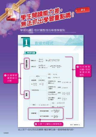
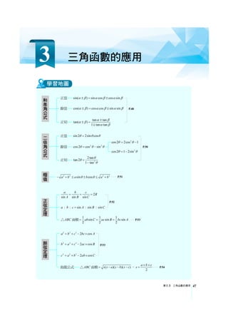
單元3 三角函數的應用
3 三角函數的應用
47
22 2 2
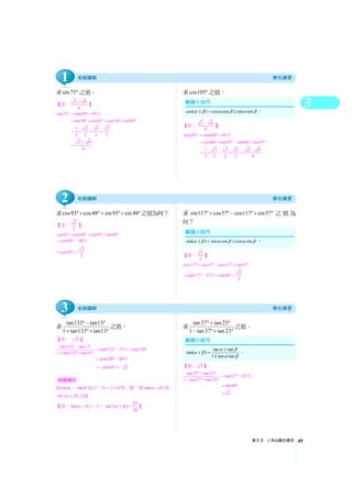
sin cosa b a b a bθ θ− + ≤ ± ≤ +
極值
正弦定理
2
sin sin sin
a b c
R
A B C
= = =
: : sin : sin : sina b c A B C=
ABC△ 面積 1 1 1
sin sin sin
2 2 2
ab C ac B bc A= = =
和差角公式
正弦 sin( ) sin cos cos sinα β α β α β± = ±
餘弦 cos( ) cos cos sin sinα β α β α β± = ∓
正切 tan tan
tan( )
1 tan tan
α βα β
α β
±
± =
∓
P.48
P.51
P.52
P.53
P.53
餘弦定理
2 2 2
2 cosa b c bc A= + − ×
2 2 2
2 cosb a c ac B= + − ×
2 2 2
2 cosc a b ab C= + − ×
海龍公式 ABC△ 面積 ( )( )( )s s a s b s c= − − − , 2
a b c
s
+ +
= P.54
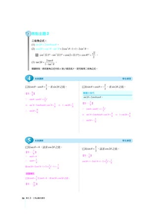
二倍角公式
正弦 sin 2 2sin cosθ θ θ=
餘弦 2 2
cos2 cos sinθ θ θ= −
正切 2
2tan
tan2
1 tan
θ
θ
θ
=
−
2
cos2 2cos 1θ θ= −
2
cos 2 1 2sinθ θ= −
P.50
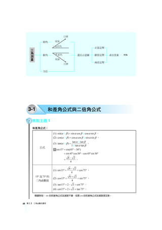
單元3 三角函數的應用52
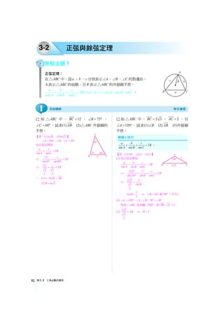
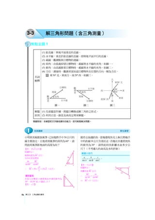
3-2 正弦與餘弦定理
焦點主題1
正弦定理:
在ABC△ 中,設a 、b 、c 分別表示 A∠ 、 B∠ 、 C∠ 的對邊長,
Δ表示 ABC△ 的面積,且R 表示 ABC△ 的外接圓半徑。
2
sin sin sin
a b c
R
A B C
= = = ⇒ sin sin sina b c A B C=: : : : 。
已 知 ABC△ 中 , 12BC = , 75B∠ = ° ,
60C∠ = °,試求(1) AB (2) ABC△ 外接圓的
半徑。
【答:(1) 6 6 (2) 6 2 】
∵ 180 45A B C∠ = °−∠ −∠ = °
由正弦定理知
2
sin sin
a c
R
A C
= =
⇒ 12
2
sin45 sin60
c
R= =
° °
⇒ 12
2
2 3
2 2
c
R= =
∴ (1) 6 6c AB= =
(2) 6 2R =
已知 ABC△ 中, 2 3BC = , 2AC = ,且
120A∠ = °,試求(1) B∠ (2) AB (3)外接圓
半徑。
【答:(1) 30° (2) 2 (3) 2 】
(1) 由正弦定理知
2
sin sin sin
a b c
R
A B C
= = =
⇒ 2 3 2
2
sin120 sin sin
c
R
B C
= = =
°
⇒ 2 3 2
sin3
2
B
=
∴ 1
sin
2
B = ⇒ 30B∠ = ° 或150°(不合)
(2) 180 30C A B B∠ = °−∠ −∠ = °=∠
得知 ABC△ 為等腰三角形,即 2AB AC= =
(3)
2 3
2
3
2
R= ⇒ 2R =
2
sin sin sin
a b c
R
A B C
= = = 。
1
10.
3
單元3 三角函數的應用 53
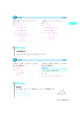
已知ABC△ 中, : : 1 : 2 : 3A B C∠ ∠ ∠ = ,
求 : :a b c 。
【答:1 : 3 : 2 】
∵ 1
180 30
1 2 3
A∠ = °× = °
+ +
2
180 60
1 2 3
B∠ = °× = °
+ +
3
180 90
1 2 3
C∠ = °× = °
+ +
∴ : : sin : sin : sina b c A B C=
1 3
: : 1
2 2
=
1 : 3 : 2=
ABC△ 中, : : 1 : 2 : 1A B C∠ ∠ ∠ = ,
求 : :a b c 。
【答:1 : 2 : 1】
∵ 1
180 45
1 2 1
A C∠ = °× = °=∠
+ +
且 2
180 90
1 2 1
B∠ = °× = °
+ +
∴ : : sin : sin : sina b c A B C=
2 2
: 1 :
2 2
=
2 : 2 : 2=
1 : 2 : 1=
焦點主題2
三角形面積公式:
1 1 1
sin sin sin
2 2 2
a b C a c B b c AΔ = × × × = × × × = × × × 。
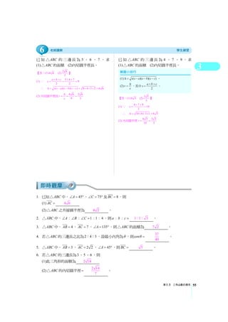
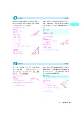
ABC△ 中,若 4AB = , 10AC = , 60A∠ = °,
則 ABC△ 面積為何?
【答:10 3 】
1
sin
2
ABC b c AΔ = × × ×
1
10 4 sin60
2
= × × × °
10 3=
ABC△ 中,若 6AB = , 8BC = , 30B∠ = °,
則 ABC△ 面積為何?
【答:12 】
1
sin
2
ABC a c BΔ = × × × 1
8 6 sin30
2
= × × × ° 12=
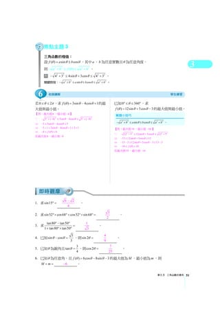
焦點主題3
餘弦定理:
在 ABC△ 中,若a 、b 、c 分別表示 A∠ 、 B∠ 、 C∠ 的對邊長,則
2 2 2
2 2 2
2 2 2
2 cos
2 cos
2 cos
a b c bc A
b a c ac B
c a b ab C
⎧ = + − ×
⎪
= + − ×⎨
⎪ = + − ×⎩
。
1
sin
2
ABC ac BΔ = (兩邊及其夾角)。
3
2
11.
單元3 三角函數的應用54
ABC△ 中,已知60A∠ = °, 6AC = , 8AB = ,
試求BC 的長度。
【答:2 13 】
由餘弦定理知
∵ 2 2 2
2 cosa b c bc A= + − ×
⇒ 2 2 2
6 8 2 6 8 cos60a = + − × × × °
36 64 48 52= + − =
∴ 52 2 13BC a= = =
ABC△ 中,已知 120C∠ = ° , 4AC = ,
3BC = ,試求AB 的長度。
【答: 37 】
由餘弦定理知
∵ 2 2 2
2 cosc a b ab C= + − ×
⇒ 2 2 2
3 4 2 3 4 cos120c = + − × × × °
1
9 16 2 3 4 ( )
2
= + − × × × − 37=
∴ 37AB c= =
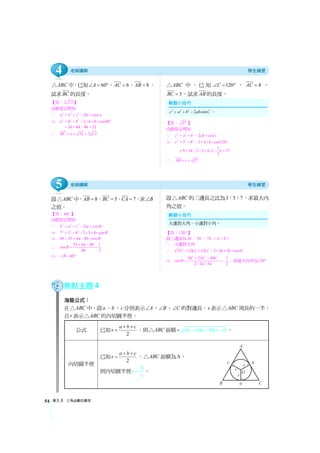
設 ABC△ 中, 8AB = , 5BC = , 7CA = ,求 B∠
之值。
【答:60° 】
由餘弦定理知
∵ 2 2 2
2 cosb a c ac B= + − ×
⇒ 2 2 2
7 5 8 2 5 8 cosB= + − × × ×
⇒ 49 25 64 80 cosB= + − ×
∴ 25 64 49 1
cos
80 2
B
+ −
= =
⇒ 60B∠ = °
設 ABC△ 的三邊長之比為3 5 7: : ,求最大內
角之值。
【答:120° 】
設三邊長為3k ,5k ,7k ( 0k )
∵ 大邊對大角
∴ 2 2 2
(7 ) (3 ) (5 ) 2 3 5 cosk k k k k θ= + − × × ×
⇒
2 2 2
9 25 49 1
cos
2 3 5 2
k k k
k k
θ
+ −
= = −
× ×
,故最大內角為120°
焦點主題4
海龍公式:
在 ABC△ 中,設a、b 、c 分別表示 A∠ 、 B∠ 、 C∠ 的對邊長,s 表示 ABC△ 周長的一半,
且r 表示 ABC△ 的內切圓半徑。
公式 已知 2
a b c
s
+ +
= ,則 ABC△ 面積 ( )( )( )s s a s b s c−= − − 。
內切圓半徑
已知 2
a b c
s
+ +
= , ABC△ 面積為Δ,
則內切圓半徑r
s
Δ
= 。
2 2 2
2 cosc a b ab C= + − 。
大邊對大角,小邊對小角。
5
4

![3
單元3 三角函數的應用 59
( B )10. 若 ABC△ 之三邊長為4 、5 、6 ,則此三角形的面積為 (A) 15
7
8
平方單位
(B)15
7
4
平方單位 (C)15
7
2
平方單位 (D)15 7 平方單位。
( C )11. 靖苓站在85 大樓前150公尺處,她必須抬頭60° 才可以看到此大樓的最高點,則此
大樓的高度為 (A)150公尺 (B)150 2 公尺 (C)150 3 公尺 (D)300公尺。
( A )12. 某湖邊有三點A、B、C,若從C 點測出 60ACB∠ = °, 200AC = 公尺及 100BC = 公
尺,則AB = (A)100 3 公尺 (B)200 3 公尺 (C)100公尺 (D)200 公尺。
( C )1. 設圓之半徑為6 ,則以40° 為圓心角的扇形面積為何? (A)π (B)2π (C)4π
(D)8π 。 [103 統測(A)]
★( A )2. 已知一矩形的長為2cos1 cos2° ° ,寬為2sin1 csc4° °,則此矩形面積為何? (A)1
(B)2 (C)3 (D)4 。 [103 統測(B)]
★( C )3. 已知 ABC△ 三邊長a ,b ,c 滿足 2 2
( ) (2 3)a b c ab− = − + ,若 C∠ 為邊長c 所對應
的角,則 C∠ = (A)30° (B)60° (C)150° (D)120° 。 [103 統測(B)]
( D )4. 已知某銳角θ 滿足 4
cos
5
θ = ,求tan 2θ = (A)13
12
(B) 4
3
(C)12
5
(D) 24
7
。
[103 統測(B)]
( C )5. 在 ABC△ 中,設三邊長之比 7 5 3AB BC CA =: : : : ,則 ABC△ 之最大內角為何?
(A)75° (B)90° (C)120° (D)135° 。 [103 統測(C)]
★( B )6. 已知 ABC△ 中 6AC = , 2 3BC = , 30A∠ = °, 90B∠ °,則 ABC△ 之面積為何?
(A)2 3 (B)3 3 (C)4 3 (D)6 3 。 [101 統測(B)]
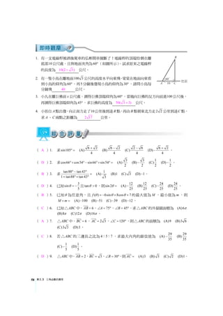
( B )7. 已知 ABC△ 中, 90C∠ = °,D在BC 線段上,且 50AC = ,
30ABC∠ = °, 45ADC∠ = °,如圖所示,則BD = (A)50
(B)50( 3 1)− (C)50 3 (D)100。 [100 統測(B)]
( C )8. 若 ABC△ 中, 6BC = , 2 3AC = ,且 60A∠ = °,則
ABC△ 之面積為何? (A)2 3 (B)4 3 (C)6 3 (D)8 3 。 [99 統測(B)]
( A )9. 某湖邊上有三點A、B 和C,若從C 點處測出 60ACB∠ = °、AC 長為200 公尺及BC
長為100公尺,則AB 長為多少公尺? (A)100 3 (B)200 3 (C)100 (D)200 。
[94 統測(A)]
( B )10. 某甲在平地上看一直立旗桿桿頂的仰角為30° ,今某甲朝旗桿的方向前進30 公尺
後,再看同一旗桿桿頂的仰角為60° ,則此時某甲離旗桿有多少公尺? (A)12
(B)15 (C)18 (D)15 3 。 [93 統測(B)]
「★」代表難題](https://image.slidesharecdn.com/3295-150503231022-conversion-gate01/85/B-C-16-320.jpg)


![龍騰[掌握]數學B複習講義](https://cdn.slidesharecdn.com/ss_thumbnails/3292-150503225400-conversion-gate02-thumbnail.jpg?width=640&height=640&fit=bounds)

![龍騰[突破]數學B複習講義](https://cdn.slidesharecdn.com/ss_thumbnails/3291-150503225147-conversion-gate01-thumbnail.jpg?width=640&height=640&fit=bounds)


![龍騰[掌握]數學C複習講義](https://cdn.slidesharecdn.com/ss_thumbnails/3290-150503224955-conversion-gate01-thumbnail.jpg?width=640&height=640&fit=bounds)
![龍騰[掌握]數學A複習講義](https://cdn.slidesharecdn.com/ss_thumbnails/3294-150503230824-conversion-gate02-thumbnail.jpg?width=640&height=640&fit=bounds)


