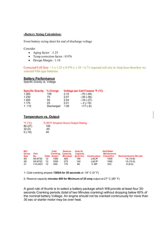
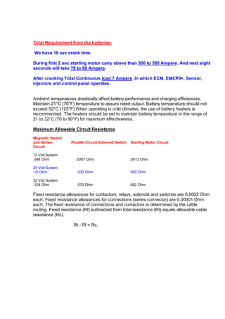
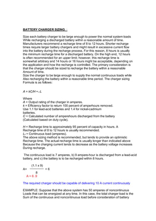
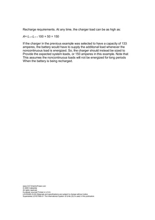
BATTERY SIZING FOR ENGINE STARTING APPLICATIONS.
Depending on the design, a diesel engine might be started by an air system or an
electric motor (starting motor). Electric starting is the most convenient to use, is
usually the least expensive, and is the most adaptable method for remote control
and automation. The ambient temperature and lubricating oil viscosity affect the
starting ability of a diesel engine. The diesel relies on the heat generated by
compression to ignite the fuel. When first starting, this compression and heat is
created by the diesel cranking (starting) process, which is a function of the
cranking speed and cranking time. When the engine is cold, longer cranking
periods are required to develop ignition temperatures.
The battery powers an electric starting motor to accomplish this cranking process.
Lubricating oil imposes the greatest load on the cranking motor; oil viscosity varies with oil
type and temperature. For example, Society of Automotive Engineers (SAE) 30 oil
viscosity approaches that of grease below 0 °C (32 °F).
Either lead-acid or nickel-cadmium batteries can be used for engine starting.
The nickel-cadmium type is often used so that the battery can be located very
near the engine, which is usually a higher ambient temperature environment.
Also, nickel-cadmium batteries are capable of very high-rate discharges for the
few seconds needed for an engine cranking application.
Battery Specifications :
Type : Lead-Acid, Nickel-Cadmium
Nominal Voltage : 24VDC
Rated Capacity : 190AH
Number of Cells : 24
End of Discharge Voltage: 1.1Volt/cell
Maximum System Voltage 32 Volts
Minimum System Voltage 18 Volts
Temperature Correction Factors for Vented Lead-Acid Cells (1.260 Specific Gravity)
Electrolyte Cell Size
Temperature Correction Factor
(F) (C) (F) (C) C.F (F) (C) C.F
25 -3.9 1.520 71 21.7 1.034 85 29.4 0.960
30 -1.1 1.430 72 22.2 1.029 86 30.0 0.956
35 1.7 1.350 73 22.8 1.023 87 30.6 0.952
40 4.4 1.300 74 23.4 1.017 88 31.1 0.948
45 7.2 1.250 75 23.9 1.011 89 31.6 0.944
50 10.0 1.190 76 24.5 1.006 90 32.2 0.940
55 12.8 1.150 77 25.0 1.000 95 35.0 0.930
60 15.6 1.110 78 25.6 0.994 100 37.8 0.910
65 18.3 1.080 79 26.1 0.987 105 40.6 0.890
66 18.9 1.072 80 26.7 0.980 110 43.3 0.880
67 19.4 1.064 81 27.2 0.976 115 46.1 0.870
68 20.0 1.056 82 27.8 0.972 120 48.9 0.860
69 20.6 1.048 83 28.3 0.968 125 51.7 0.850
70 21.1 1.040 84 28.9 0.964
The battery sizing methodology determines the cell size for the defined duty
cycle when the battery capacity is 100 percent and at the reference temperature
of 25 °C (77 °F). For most batteries, end-of-life occurs when capacity falls to 80
percent of the rated capacity. Also, depending on the installation, the actual
battery temperature might be well below 25 °C (77 °F), and battery capacity
decreases as temperature decreases. Apply correction factors to the calculated
cell size to account for these effects. The net result is that the selected cell size
must be larger so that it can meet its design requirements at end-of-life at the
design low temperature.
Under ideal conditions, a battery can have 90 percent to over 100 percent
capacity when new. As the battery ages, its capacity will eventually fall to 80
percent, which is the commonly accepted point at which the battery should be
replaced. Below this capacity, the rate of degradation can increase rapidly. As
part of the battery sizing process, size the battery so that it can fulfill the duty
cycle requirements at its end of life. Apply the following correction factor to the
calculated cell size; the calculated cell size is made 25 percent larger to ensure
that it can supply the required load at end of life:
Aging Correction Factor =1/0.8 =1.25
-Battery Sizing Calculation:
From battery sizing sheet for end of discharge voltage
Consider
 Aging factor :1.25
 Temp correction factor : 0.976
 Design Margin : 1.10
Corrected Cell Size = 5 x 1.25 x 0.976 x 1.10 = 6.71 required cell size in Amp hour therefore we
selected 9Ah type batteries
Battery Performance
Specific Gravity vs. Voltage
Specific Gravity % Charge Voltage per Cell Freezes °F (°C)
1.260 100 2.10 –70 (–94)
1.230 75 2.07 –39 (–56)
1.200 50 2.04 –16 (–27)
1.170 25 2.01 – 2 (–19)
1. 110 Discharged 1.95 +17 (–8)
Temperature vs. Output
°F (°C) % 80°F Ampere Hours Output Rating
80 (27) 100
32 (0) 65
0 (-18) 40
BCI Cold Reserve Amp Hr. Add Water
Group Part Cranking Capacity Capacity Maintenance
Size No. Volts Amps1 Minutes2 @ 20 Hrs. Construction Check/Hrs. Nominal Acid to fill Liter
4D 9X-9730 12 1300 400 190 LAC/P 1000 14 (14.8)
4D 9X-9720 12 1000 275 140 LAC/P 1000 15 (15.9)
31 115-2421 12 950 170 90 C MF 333 6 (6.6)
1- Cold cranking ampere 1300A for 30 seconds at -18° C (0° F)
2- Reserve capacity minutes 400 for Minimum of 25 amp output at 27° C (80° F)
A good rule of thumb is to select a battery package which Will provide at least four 30-
seconds Cranking periods (total of two Minutes cranking) without dropping below 60% of
the nominal battery Voltage. An engine should not be cranked continuously for more than
30 sec or starter motor may be over heat.
Total Requirement from the batteries:
We have 10 sec crank time.
During first 2 sec starting motor carry above than 300 to 380 Ampere. And next eight
seconds will take 70 to 80 Ampere.
After cranking Total Continuous load 7 Ampere .In which ECM, EMCPII+, Sensor,
injectors and control panel operates.
Ambient temperatures drastically affect battery performance and charging efficiencies.
Maintain 21°C (70°F) temperature to assure rated output. Battery temperature should not
exceed 52°C (125°F).When operating in cold climates, the use of battery heaters is
recommended. The heaters should be set to maintain battery temperature in the range of
21 to 32°C (70 to 90°F) for maximum effectiveness.
Maximum Allowable Circuit Resistance
Magnetic Switch
and Series- Parallel Circuit Solenoid Switch Starting Motor Circuit
Circuit
12 Volt System
.048 Ohm .0067 Ohm .0012 Ohm
24 Volt System
.10 Ohm .030 Ohm .002 Ohm
32 Volt System
.124 Ohm .070 Ohm .002 Ohm
Fixed resistance allowances for contactors, relays, solenoid and switches are 0.0002 Ohm
each. Fixed resistance allowances for connections (series connector) are 0.00001 Ohm
each. The fixed resistance of connections and contactors is determined by the cable
routing. Fixed resistance (Rf) subtracted from total resistance (Rt) equals allowable cable
resistance (Rc).
Rt - Rf = Rc.
BATTERY CHARGER SIZING. :
Size each battery charger to be large enough to power the normal system loads
While recharging a discharged battery within a reasonable amount of time.
Manufacturers recommend a recharge time of 8 to 12 hours. Shorter recharge
times require larger battery chargers and might result in excessive current flow
into the battery during the recharge process. For this reason, 8 hours is usually
the minimum recharge time for a discharged battery. On the high end, 12 hours
is often recommended for an upper limit; however, this recharge time is
somewhat arbitrary and 14 hours or 16 hours might be acceptable, depending on
the application and how the recharge is controlled. The primary consideration is
that the charger should be sized to recharge the battery within a reasonable
Amount of time.
Size the charger to be large enough to supply the normal continuous loads while
Also recharging the battery within a reasonable time period. The charger sizing
Formula is as follows:
A = kC/H + c L
Where
A = Output rating of the charger in amperes.
k = Efficiency factor to return 100 percent of amperhours removed.
Use 1.1 for lead-acid batteries and 1.4 for nickel-cadmium
batteries.
C = Calculated number of amperehours discharged from the battery
(Calculated based on duty cycle).
H = Recharge time to approximately 95 percent of capacity in hours. A
Recharge time of 8 to 12 hours is usually recommended.
Lc = Continuous load (amperes).
The above sizing method is recommended, but tends to provide an optimistic
Recharge time. The actual recharge time is usually longer than indicated above
Because the charging current tends to decrease as the battery voltage increases
During recharge.
The continuous load is 7 amperes, b) 9 ampere-hour is discharged from a lead-acid
battery, and c) the battery is to be recharged within 8 hours.
(1.1 x 9)
A= + 6
8
A = 6 .9
The required charger should be capable of delivering 10 A current continuously
EXAMPLE: Suppose that the above system has 50 amperes of noncontinuous
Loads that can be energized at any time. In this case, the total charger load is the
Sum of the continuous and noncontinuous load before consideration of battery
Recharge requirements. At any time, the charger load can be as high as:
A= L c + L n = 100 + 50 = 150
If the charger in the previous example was selected to have a capacity of 133
amperes, the battery would have to supply the additional load whenever the
noncontinuous load is energized. So, the charger should instead be sized to
Provide the expected system loads, or 150 amperes in this example. Note that
This assumes the noncontinuous loads will not be energized for long periods
When the battery is being recharged.
www.CAT-ElectricPower.com
© 2000 Caterpillar
All rights reserved.
European sourced Printed in U.S.A.
LEHX0265 (5-00) Materials and specifications are subject to change without notice.
Supersedes LEHX7069-01 The International System of Units (SI) is used in this publication.

Battery specifications and calculation

  • 1.
    BATTERY SIZING FORENGINE STARTING APPLICATIONS. Depending on the design, a diesel engine might be started by an air system or an electric motor (starting motor). Electric starting is the most convenient to use, is usually the least expensive, and is the most adaptable method for remote control and automation. The ambient temperature and lubricating oil viscosity affect the starting ability of a diesel engine. The diesel relies on the heat generated by compression to ignite the fuel. When first starting, this compression and heat is created by the diesel cranking (starting) process, which is a function of the cranking speed and cranking time. When the engine is cold, longer cranking periods are required to develop ignition temperatures. The battery powers an electric starting motor to accomplish this cranking process. Lubricating oil imposes the greatest load on the cranking motor; oil viscosity varies with oil type and temperature. For example, Society of Automotive Engineers (SAE) 30 oil viscosity approaches that of grease below 0 °C (32 °F). Either lead-acid or nickel-cadmium batteries can be used for engine starting. The nickel-cadmium type is often used so that the battery can be located very near the engine, which is usually a higher ambient temperature environment. Also, nickel-cadmium batteries are capable of very high-rate discharges for the few seconds needed for an engine cranking application. Battery Specifications : Type : Lead-Acid, Nickel-Cadmium Nominal Voltage : 24VDC Rated Capacity : 190AH Number of Cells : 24 End of Discharge Voltage: 1.1Volt/cell Maximum System Voltage 32 Volts Minimum System Voltage 18 Volts
  • 2.
    Temperature Correction Factorsfor Vented Lead-Acid Cells (1.260 Specific Gravity) Electrolyte Cell Size Temperature Correction Factor (F) (C) (F) (C) C.F (F) (C) C.F 25 -3.9 1.520 71 21.7 1.034 85 29.4 0.960 30 -1.1 1.430 72 22.2 1.029 86 30.0 0.956 35 1.7 1.350 73 22.8 1.023 87 30.6 0.952 40 4.4 1.300 74 23.4 1.017 88 31.1 0.948 45 7.2 1.250 75 23.9 1.011 89 31.6 0.944 50 10.0 1.190 76 24.5 1.006 90 32.2 0.940 55 12.8 1.150 77 25.0 1.000 95 35.0 0.930 60 15.6 1.110 78 25.6 0.994 100 37.8 0.910 65 18.3 1.080 79 26.1 0.987 105 40.6 0.890 66 18.9 1.072 80 26.7 0.980 110 43.3 0.880 67 19.4 1.064 81 27.2 0.976 115 46.1 0.870 68 20.0 1.056 82 27.8 0.972 120 48.9 0.860 69 20.6 1.048 83 28.3 0.968 125 51.7 0.850 70 21.1 1.040 84 28.9 0.964 The battery sizing methodology determines the cell size for the defined duty cycle when the battery capacity is 100 percent and at the reference temperature of 25 °C (77 °F). For most batteries, end-of-life occurs when capacity falls to 80 percent of the rated capacity. Also, depending on the installation, the actual battery temperature might be well below 25 °C (77 °F), and battery capacity decreases as temperature decreases. Apply correction factors to the calculated cell size to account for these effects. The net result is that the selected cell size must be larger so that it can meet its design requirements at end-of-life at the design low temperature. Under ideal conditions, a battery can have 90 percent to over 100 percent capacity when new. As the battery ages, its capacity will eventually fall to 80 percent, which is the commonly accepted point at which the battery should be replaced. Below this capacity, the rate of degradation can increase rapidly. As part of the battery sizing process, size the battery so that it can fulfill the duty cycle requirements at its end of life. Apply the following correction factor to the calculated cell size; the calculated cell size is made 25 percent larger to ensure that it can supply the required load at end of life: Aging Correction Factor =1/0.8 =1.25
  • 3.
    -Battery Sizing Calculation: Frombattery sizing sheet for end of discharge voltage Consider  Aging factor :1.25  Temp correction factor : 0.976  Design Margin : 1.10 Corrected Cell Size = 5 x 1.25 x 0.976 x 1.10 = 6.71 required cell size in Amp hour therefore we selected 9Ah type batteries Battery Performance Specific Gravity vs. Voltage Specific Gravity % Charge Voltage per Cell Freezes °F (°C) 1.260 100 2.10 –70 (–94) 1.230 75 2.07 –39 (–56) 1.200 50 2.04 –16 (–27) 1.170 25 2.01 – 2 (–19) 1. 110 Discharged 1.95 +17 (–8) Temperature vs. Output °F (°C) % 80°F Ampere Hours Output Rating 80 (27) 100 32 (0) 65 0 (-18) 40 BCI Cold Reserve Amp Hr. Add Water Group Part Cranking Capacity Capacity Maintenance Size No. Volts Amps1 Minutes2 @ 20 Hrs. Construction Check/Hrs. Nominal Acid to fill Liter 4D 9X-9730 12 1300 400 190 LAC/P 1000 14 (14.8) 4D 9X-9720 12 1000 275 140 LAC/P 1000 15 (15.9) 31 115-2421 12 950 170 90 C MF 333 6 (6.6) 1- Cold cranking ampere 1300A for 30 seconds at -18° C (0° F) 2- Reserve capacity minutes 400 for Minimum of 25 amp output at 27° C (80° F) A good rule of thumb is to select a battery package which Will provide at least four 30- seconds Cranking periods (total of two Minutes cranking) without dropping below 60% of the nominal battery Voltage. An engine should not be cranked continuously for more than 30 sec or starter motor may be over heat.
  • 4.
    Total Requirement fromthe batteries: We have 10 sec crank time. During first 2 sec starting motor carry above than 300 to 380 Ampere. And next eight seconds will take 70 to 80 Ampere. After cranking Total Continuous load 7 Ampere .In which ECM, EMCPII+, Sensor, injectors and control panel operates. Ambient temperatures drastically affect battery performance and charging efficiencies. Maintain 21°C (70°F) temperature to assure rated output. Battery temperature should not exceed 52°C (125°F).When operating in cold climates, the use of battery heaters is recommended. The heaters should be set to maintain battery temperature in the range of 21 to 32°C (70 to 90°F) for maximum effectiveness. Maximum Allowable Circuit Resistance Magnetic Switch and Series- Parallel Circuit Solenoid Switch Starting Motor Circuit Circuit 12 Volt System .048 Ohm .0067 Ohm .0012 Ohm 24 Volt System .10 Ohm .030 Ohm .002 Ohm 32 Volt System .124 Ohm .070 Ohm .002 Ohm Fixed resistance allowances for contactors, relays, solenoid and switches are 0.0002 Ohm each. Fixed resistance allowances for connections (series connector) are 0.00001 Ohm each. The fixed resistance of connections and contactors is determined by the cable routing. Fixed resistance (Rf) subtracted from total resistance (Rt) equals allowable cable resistance (Rc). Rt - Rf = Rc.
  • 5.
    BATTERY CHARGER SIZING.: Size each battery charger to be large enough to power the normal system loads While recharging a discharged battery within a reasonable amount of time. Manufacturers recommend a recharge time of 8 to 12 hours. Shorter recharge times require larger battery chargers and might result in excessive current flow into the battery during the recharge process. For this reason, 8 hours is usually the minimum recharge time for a discharged battery. On the high end, 12 hours is often recommended for an upper limit; however, this recharge time is somewhat arbitrary and 14 hours or 16 hours might be acceptable, depending on the application and how the recharge is controlled. The primary consideration is that the charger should be sized to recharge the battery within a reasonable Amount of time. Size the charger to be large enough to supply the normal continuous loads while Also recharging the battery within a reasonable time period. The charger sizing Formula is as follows: A = kC/H + c L Where A = Output rating of the charger in amperes. k = Efficiency factor to return 100 percent of amperhours removed. Use 1.1 for lead-acid batteries and 1.4 for nickel-cadmium batteries. C = Calculated number of amperehours discharged from the battery (Calculated based on duty cycle). H = Recharge time to approximately 95 percent of capacity in hours. A Recharge time of 8 to 12 hours is usually recommended. Lc = Continuous load (amperes). The above sizing method is recommended, but tends to provide an optimistic Recharge time. The actual recharge time is usually longer than indicated above Because the charging current tends to decrease as the battery voltage increases During recharge. The continuous load is 7 amperes, b) 9 ampere-hour is discharged from a lead-acid battery, and c) the battery is to be recharged within 8 hours. (1.1 x 9) A= + 6 8 A = 6 .9 The required charger should be capable of delivering 10 A current continuously EXAMPLE: Suppose that the above system has 50 amperes of noncontinuous Loads that can be energized at any time. In this case, the total charger load is the Sum of the continuous and noncontinuous load before consideration of battery
  • 6.
    Recharge requirements. Atany time, the charger load can be as high as: A= L c + L n = 100 + 50 = 150 If the charger in the previous example was selected to have a capacity of 133 amperes, the battery would have to supply the additional load whenever the noncontinuous load is energized. So, the charger should instead be sized to Provide the expected system loads, or 150 amperes in this example. Note that This assumes the noncontinuous loads will not be energized for long periods When the battery is being recharged. www.CAT-ElectricPower.com © 2000 Caterpillar All rights reserved. European sourced Printed in U.S.A. LEHX0265 (5-00) Materials and specifications are subject to change without notice. Supersedes LEHX7069-01 The International System of Units (SI) is used in this publication.