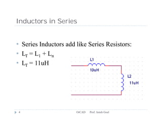
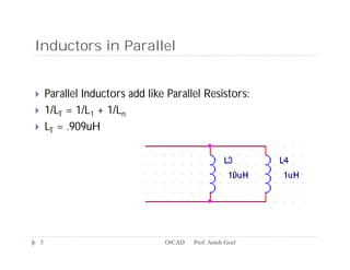
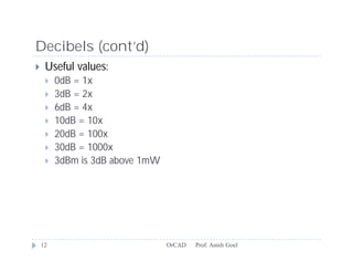
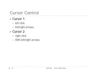
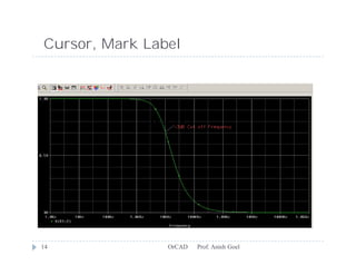
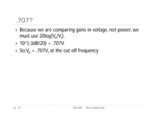
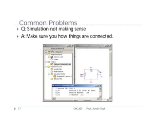
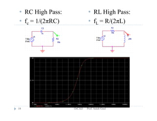
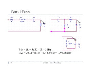
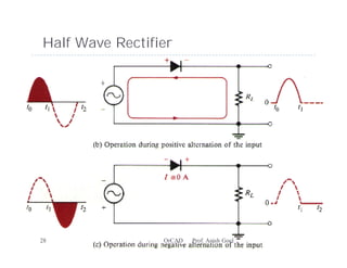
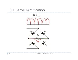
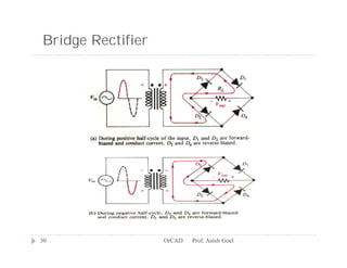
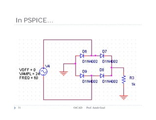
Basic Circuit Simulation using
                       OrCAD
                 Prof. Anish Goel
Capacitors in Series


       Series Capacitors add like Parallel Resistors:
       1/CT = 1/C1 + 1/Cn
       CT = .909uF


    2                            OrCAD   Prof. Anish Goel
Capacitors in Parallel


       Parallel Capacitors add like Series Resistors:
       CT = C1 + Cn
       CT = 11uF


    3                            OrCAD   Prof. Anish Goel
Inductors in Series


• Series Inductors add like Series Resistors:
• LT = L1 + Ln
• LT = 11uH


4                      OrCAD   Prof. Anish Goel
Inductors in Parallel


       Parallel Inductors add like Parallel Resistors:
       1/LT = 1/L1 + 1/Ln
       LT = .909uH


    5                              OrCAD   Prof. Anish Goel
Capacitor Review
       Starts as short circuit, ends as open circuit
       iC = C*dVC/dt
       Open circuit at low frequencies
       Short circuit at high frequencies


    6                              OrCAD   Prof. Anish Goel
Inductor Review
       Starts as open circuit, ends as short circuit
       VL = L*dI/dt
       Short circuit at low frequencies
       Open circuit at high frequencies


    7                              OrCAD   Prof. Anish Goel
Filters
       Use frequency response characteristics of C and L to
        filter frequency components out of a time domain signal.
       Low Pass
       High Pass
       Band Pass
       Band Stop


    8                            OrCAD   Prof. Anish Goel
Low Pass Filters
   RC Low Pass: fcut off frequency = 1/(2πRC)

                                      • Component selection
                                      • RC vs. RL filters
   RL Low Pass: fc = R/(2πL)


9                             OrCAD   Prof. Anish Goel
AC Analysis (freq)
   Logarithmic plot (count by decades)
   fc defined as –3dB of input, “Half power point”
   Copy paste data points to excel!


    10                        OrCAD   Prof. Anish Goel
Decibels
    Measure of gain. Instead of saying gain is 100,000x, some
     engineers prefer to say it as 100dB.
    Power gain: dB = 10 log(Po/Pi)
    Voltage gain: dB = 20 log(Vo/Vi)
    Always a relationship


    11                         OrCAD   Prof. Anish Goel
Decibels (cont’d)
    Useful values:
        0dB = 1x
        3dB = 2x
        6dB = 4x
        10dB = 10x
        20dB = 100x
        30dB = 1000x
        3dBm is 3dB above 1mW


    12                           OrCAD   Prof. Anish Goel
Cursor Control
    Cursor 1:
        left click
        left/right arrows
    Cursor 2:
        right click
        Shift left/right arrows


    13                             OrCAD   Prof. Anish Goel
Cursor, Mark Label


14              OrCAD   Prof. Anish Goel
.707?
    Because we are comparing gains in voltage, not power, we
     must use 20log(Vo/Vi).
    10^(-3dB/20) = .707V
    So,Vo = .707Vi at the cut off frequency


    15                        OrCAD   Prof. Anish Goel
Bode Plot (dB, logarithmic)


16                 OrCAD   Prof. Anish Goel
Common Problems
    Q: Simulation not making sense
    A: Make sure you how things are connected.


17                           OrCAD   Prof. Anish Goel
• RC High Pass:            • RL High Pass:
• fc = 1/(2πRC)            • fL = R/(2πL)


18                OrCAD   Prof. Anish Goel
Band Pass
                                       HP         LP


     BW = (fc + 3dB) – (fc – 3dB)
     BW = 200.171kHz – 494.694Hz = 199.676kHz


19                     OrCAD   Prof. Anish Goel
Response


20         OrCAD   Prof. Anish Goel
Band Stop

                                     HP         LP


     BW = 16.216kHz –6.0833kHz = 10.133kHz


21                   OrCAD   Prof. Anish Goel
Response


22         OrCAD   Prof. Anish Goel
Transformer


   Easy to “Step down” or “Step up” an AC voltage
   (This is why AC is used for home power delivery instead of
    DC.)
   VP/VS = NP/NS => VS = VPNS/NP
   Excellent DC filter because VS = NS*dΦ/dt


     23                        OrCAD   Prof. Anish Goel
In PSPICE…
    Coupling = 1
    Lx_Value = Nx2
        should be between 1mH and 1H


    24                          OrCAD   Prof. Anish Goel
Diode


   Allow current to flow only in 1 direction
   Flow from left (annode+) to right (cathode-) is forward
    biased.
   Diode causes a voltage drop due to its activation voltage.
       Silicon - .7V
       Germanium - .3V
   Cathode connected to a battery is reversed biased. (blocked)
   Perform DC Sweep and Transient Response (use D1N4002)

        25                     OrCAD   Prof. Anish Goel
Activation Voltage


26                   OrCAD   Prof. Anish Goel
Transient Response
Half Wave Rectifier


27                    OrCAD   Prof. Anish Goel
Half Wave Rectifier


28               OrCAD   Prof. Anish Goel
Full Wave Rectification


29               OrCAD   Prof. Anish Goel
Bridge Rectifier


30                 OrCAD   Prof. Anish Goel
In PSPICE…


31           OrCAD   Prof. Anish Goel
Full Wave Rectifier


32                    OrCAD   Prof. Anish Goel
Smoothing
    Use capacitor to smooth the ripples of the rectified
     wave form.


                               (Negative voltage)
33                           OrCAD   Prof. Anish Goel
Regulators


   Not in student addition
   Outputs a clean regulated voltage
   LM317 and 337 are +/- 2-18V variable regulators
   LM7805 is 5V regulator
   Input must be relatively steady or else regulator will fail.


     34                           OrCAD   Prof. Anish Goel

Basic circuit or cad

  • 1.
    Basic Circuit Simulationusing OrCAD Prof. Anish Goel
  • 2.
    Capacitors in Series  Series Capacitors add like Parallel Resistors:  1/CT = 1/C1 + 1/Cn  CT = .909uF 2 OrCAD Prof. Anish Goel
  • 3.
    Capacitors in Parallel  Parallel Capacitors add like Series Resistors:  CT = C1 + Cn  CT = 11uF 3 OrCAD Prof. Anish Goel
  • 4.
    Inductors in Series •Series Inductors add like Series Resistors: • LT = L1 + Ln • LT = 11uH 4 OrCAD Prof. Anish Goel
  • 5.
    Inductors in Parallel  Parallel Inductors add like Parallel Resistors:  1/LT = 1/L1 + 1/Ln  LT = .909uH 5 OrCAD Prof. Anish Goel
  • 6.
    Capacitor Review  Starts as short circuit, ends as open circuit  iC = C*dVC/dt  Open circuit at low frequencies  Short circuit at high frequencies 6 OrCAD Prof. Anish Goel
  • 7.
    Inductor Review  Starts as open circuit, ends as short circuit  VL = L*dI/dt  Short circuit at low frequencies  Open circuit at high frequencies 7 OrCAD Prof. Anish Goel
  • 8.
    Filters  Use frequency response characteristics of C and L to filter frequency components out of a time domain signal.  Low Pass  High Pass  Band Pass  Band Stop 8 OrCAD Prof. Anish Goel
  • 9.
    Low Pass Filters  RC Low Pass: fcut off frequency = 1/(2πRC) • Component selection • RC vs. RL filters  RL Low Pass: fc = R/(2πL) 9 OrCAD Prof. Anish Goel
  • 10.
    AC Analysis (freq)  Logarithmic plot (count by decades)  fc defined as –3dB of input, “Half power point”  Copy paste data points to excel! 10 OrCAD Prof. Anish Goel
  • 11.
    Decibels  Measure of gain. Instead of saying gain is 100,000x, some engineers prefer to say it as 100dB.  Power gain: dB = 10 log(Po/Pi)  Voltage gain: dB = 20 log(Vo/Vi)  Always a relationship 11 OrCAD Prof. Anish Goel
  • 12.
    Decibels (cont’d)  Useful values:  0dB = 1x  3dB = 2x  6dB = 4x  10dB = 10x  20dB = 100x  30dB = 1000x  3dBm is 3dB above 1mW 12 OrCAD Prof. Anish Goel
  • 13.
    Cursor Control  Cursor 1:  left click  left/right arrows  Cursor 2:  right click  Shift left/right arrows 13 OrCAD Prof. Anish Goel
  • 14.
    Cursor, Mark Label 14 OrCAD Prof. Anish Goel
  • 15.
    .707?  Because we are comparing gains in voltage, not power, we must use 20log(Vo/Vi).  10^(-3dB/20) = .707V  So,Vo = .707Vi at the cut off frequency 15 OrCAD Prof. Anish Goel
  • 16.
    Bode Plot (dB,logarithmic) 16 OrCAD Prof. Anish Goel
  • 17.
    Common Problems  Q: Simulation not making sense  A: Make sure you how things are connected. 17 OrCAD Prof. Anish Goel
  • 18.
    • RC HighPass: • RL High Pass: • fc = 1/(2πRC) • fL = R/(2πL) 18 OrCAD Prof. Anish Goel
  • 19.
    Band Pass HP LP BW = (fc + 3dB) – (fc – 3dB) BW = 200.171kHz – 494.694Hz = 199.676kHz 19 OrCAD Prof. Anish Goel
  • 20.
    Response 20 OrCAD Prof. Anish Goel
  • 21.
    Band Stop HP LP BW = 16.216kHz –6.0833kHz = 10.133kHz 21 OrCAD Prof. Anish Goel
  • 22.
    Response 22 OrCAD Prof. Anish Goel
  • 23.
    Transformer  Easy to “Step down” or “Step up” an AC voltage  (This is why AC is used for home power delivery instead of DC.)  VP/VS = NP/NS => VS = VPNS/NP  Excellent DC filter because VS = NS*dΦ/dt 23 OrCAD Prof. Anish Goel
  • 24.
    In PSPICE…  Coupling = 1  Lx_Value = Nx2  should be between 1mH and 1H 24 OrCAD Prof. Anish Goel
  • 25.
    Diode  Allow current to flow only in 1 direction  Flow from left (annode+) to right (cathode-) is forward biased.  Diode causes a voltage drop due to its activation voltage.  Silicon - .7V  Germanium - .3V  Cathode connected to a battery is reversed biased. (blocked)  Perform DC Sweep and Transient Response (use D1N4002) 25 OrCAD Prof. Anish Goel
  • 26.
    Activation Voltage 26 OrCAD Prof. Anish Goel
  • 27.
    Transient Response Half WaveRectifier 27 OrCAD Prof. Anish Goel
  • 28.
    Half Wave Rectifier 28 OrCAD Prof. Anish Goel
  • 29.
    Full Wave Rectification 29 OrCAD Prof. Anish Goel
  • 30.
    Bridge Rectifier 30 OrCAD Prof. Anish Goel
  • 31.
    In PSPICE… 31 OrCAD Prof. Anish Goel
  • 32.
    Full Wave Rectifier 32 OrCAD Prof. Anish Goel
  • 33.
    Smoothing  Use capacitor to smooth the ripples of the rectified wave form. (Negative voltage) 33 OrCAD Prof. Anish Goel
  • 34.
    Regulators  Not in student addition  Outputs a clean regulated voltage  LM317 and 337 are +/- 2-18V variable regulators  LM7805 is 5V regulator  Input must be relatively steady or else regulator will fail. 34 OrCAD Prof. Anish Goel