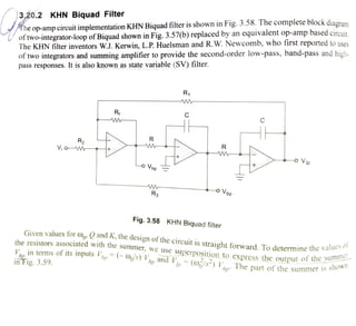
1. The op-amp circuit implementation KHN Biquad filter is shown in Fig. 3.58. The complete block diaora
of two-integrator-loop ofBiquad shown in Fig. 3.57(b) replaced by an equivalent op-amp based circuit
The KHN filter inventors W.J. Kerwin, L.P. Huelsman and R.W. Newcomb, who first reported to uses
of two integrators and summing amplifier to provide the second-order low-pass, band-pass and high
pass responses. It is also known as state variable (SV) filter.
3,20.2 KHN Biquad Filter
R1
Rf C
R
R2
RV,o M
o Vip
o Vnp
o Vbp
Ra
Fig. 3.58 KHN Biquad filter
Given values for o» and K, the
design ofthe circuit is straight forward. To determine the
vanu
es of
the resistors associated with the
summer, we use
superposition to express the output of the
su
rV in terms ofits inputs bp Os)hp and
V, (0/s) VThe part of the summer 1s
inFig. 3.59.
2. R
R
Vip O
o Vnp
RVio
VDp O
R3
Fig. 3.59
From the circuit of Fig. 3.59, we can write Vn by using superposition theorem. When V, is acting
alone and remaining inputs are connected to ground
.(3.144)Rg
Ra + R3Vhp
when hn 1S acting alone and remaining inputs are connected to groundd
..(3.145)
14 Vbe
R
R
S
Vhp2 R +R3R +R3
when acting alone and remaining inputs are connectedto ground
..(3.146)
-RsR VRVhp3
R
The overall output of the summer Vhn can be written as
hphp1+hp2hp3
...(3.147)
R
hp Ra +
R3
R VR+ RsR2
R1+
R
..(3.148)
Let we consider R= R, then the equation (3.147) becomes
2
s2R3
Vhp Ra + R3
2V +R+R3
.(3.149)Compare equations (3.140) and (3.148)
2R2
Rz+ R
R + R- 20R,
..3.150)
Ra -20-1
R2
3. For
thegiven value
of , we get either R or R, by setting any one value and other resistor is
determined from the above relation
2RK=
R+R3
K(R, + R)= 2R,
KR+R)
R3
K2+1-2R3
KI
20-1
After simplification
K 2-1/0 .(3.151)
Noteh and AIl Daee ciltoe seim LAl D: