
Recommended
Recommended
More Related Content
What's hot
What's hot (20)
Similar to Current-Series Feedback Amplifier & Barkhausen Criterion for Oscillations
Similar to Current-Series Feedback Amplifier & Barkhausen Criterion for Oscillations (20)
Recently uploaded
Recently uploaded (20)
Current-Series Feedback Amplifier & Barkhausen Criterion for Oscillations
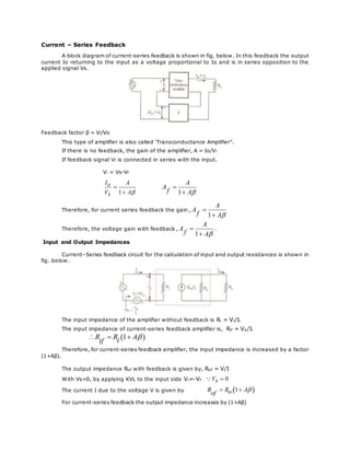
- 1. Current – Series Feedback A block diagram of current-series feedback is shown in fig. below. In this feedback the output current Io returning to the input as a voltage proportional to Io and is in series opposition to the applied signal Vs. Feedback factor β = Vf/Vo This type of amplifier is also called ‘Transconductance Amplifier”. If there is no feedback, the gain of the amplifier, A = Io/Vi If feedback signal Vf is connected in series with the input. Vi = Vs-Vf 1 I Ao V As 1 A A f A Therefore, for current series feedback the gain , 1 A A f A Therefore, the voltage gain with feedback , 1 A A f A . Input and Output Impedances Current–Series feedback circuit for the calculation of input and output resistances is shown in fig. below. The input impedance of the amplifier without feedback is Ri = Vi/Ii The input impedance of current-series feedback amplifier is, Rif = Vs/Ii 1R R Aiif Therefore, for current-series feedback amplifier, the input impedance is increased by a factor (1+Aβ). The output impedance Rof with feedback is given by, Rof = V/I With Vs=0, by applying KVL to the input side Vi=-Vf 0Vs The current I due to the voltage V is given by 1R R Aoof For current-series feedback the output impedance increases by (1+Aβ)
- 2. Conditions for oscillations (Barkhausen Criterion): Consider the block diagram of oscillator circuit shown in figure below. Fig. Block diagram of oscillator circuit. We know, V0=AVi and Vf=βV0 V A Vif For the oscillator, we want that feedback should drive the amplifier and hence Vf must act as Vi. Therefore, we can write that, Vf is sufficient to act as Vi when A 1 . And the phase of Vf is same as Vi i.e., feedback network should introduce 180o phase shift in addition to 180o phase shift introduced by amplifier. This ensures positive feedback. So total phase shift around a loop is 360o . In this condition, Vf drives the circuit and without external input circuit works as an oscillator. The two conditions described above, required to work the circuit as an oscillator are called “Barkhausen Criterion” for oscillation. The Barkhausen criterion states that, i) The magnitude of the product of the open loop gain of the amplifier (A) and the magnitude of the feedback factor β is unity. i.e., A 1 ii) The total phase shift around the closed loop is zero (or) 360o . Satisfying these conditions, the circuit works as an oscillator producing sustained oscillations of constant frequency and amplitude. RC Phase Shift Oscillator: In this oscillator the required phase shift of 180o in this feedback loop from output to input is obtained by using R and C components instead of tank circuit. The circuit diagram of RC phase shift oscillator is shown the figure. Here, a common emitter amplifier is followed by three sections of RC phase shift network, the output of the last section being returned to the input. In order to make the three RC sections identical, R3 is chosen as R3 = R-Ri, where Ri is the input impedance of the circuit.
- 3. Fig. RC phase shift oscillator. The phase shift, Φ, given by each RC section is 11tan CR . If R is made zero, then the phase shift Φ will become 90o . But making R=0 is impracticable because if R is zero, then the voltage across it will become zero. Therefore, in practice the value of R is adjusted such that Φ becomes 60o . If the value of R and C are so chosen that, for the given frequency fr, the phase shift of each RC section is 60o. Thus such a RC ladder network produces a total phase shift of 180o between its input and output voltages for the given frequency. Therefore, at the specified frequency fr, the total phase shift from the base of the transistor around the circuit and back to the base will be exactly 360o (or) 0o , thereby satisfying Barkhausen condition for oscillation. Fig. Equivalent circuit using h-parameter model. Assume the ration of the resistance RC to R be K. RCK R The modified equivalent circuit is shown in the figure below. 1 2 4 6 f RC K