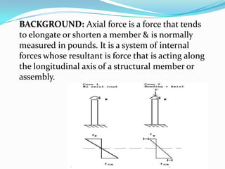
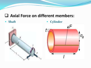
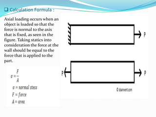
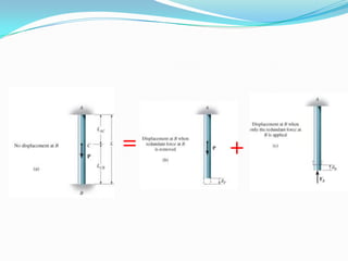
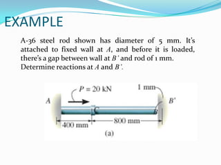
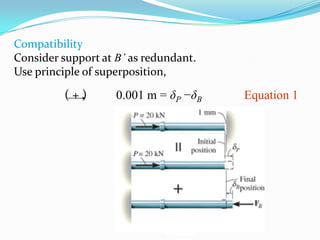
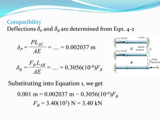
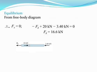
WELCOME
TO MY
PRESENTATION
AHSANULLAH UNIVERSITY OF
SCIENCE AND TECHNOLOGY
DEPARTMENT OF CIVIL ENGINEERING
CE-416;PRESTRESS CONCRETE LAB
COURSE TEACHER:MD.GALIB MUKTADIR

PRESENTATION OF AXIAL FORCE
PRESENTED BY
H.M SURUZZAMAN
ID NO:10.01.03.63
BACKGROUND: Axial force is a force that tends
to elongate or shorten a member & is normally
measured in pounds. It is a system of internal
forces whose resultant is force that is acting along
the longitudinal axis of a structural member or
assembly.
 Axial

force is the compression or
tension force acting in a member. If the
axial force acts through the censored of
the member it is called concentric
loading. If the force is not acting
through the centroid it is called
eccentric loading.

 Eccentric loading produces a moment in the beam as a

result of the load being a distaces away from the
centroid.
Learning objectives are:
-Understanding the theory ; it’s limitations, and it’
supplications for design & analysis of axial members
Axial members: Members with length significantly
greater than the largest cross sectional dimension &
with load applied along the longitudinal axis.
-Developing the discipline to draw free body diagrams &
approximate deformed shapes in the
Design & analysis of structures.
Nature of axial force:
-These forces are typically stretching force or
compression force, depending on direction.
-Shear forces occupies a similar position to axial
force, but operates perpendicular to the centre axis
of the object.
-When a force is acting directly on the central axis, it
is an axial force. These force will often compress the
axis from either end or stretch the axis in two
opposing directions; as a result the object typically
does not move.
Figure of Axial Force
 Example of axial force:A prime example of these

forces can be seen on columns within buildings.
 The column has an axis that runs through the entire
from top to bottom. The column is constantly
compressed as it supports the roof of the structure. In
the column example, the axial force runs through the
geometric centre of the form.
 ColumnForce on different members:
Axial

 Beam
 Axial Force on different members:
 Shaft

 Cylinder
 Calculation Formula :
Axial loading occurs when an
object is loaded so that the
force is normal to the axis
that is fixed, as seen in the
figure. Taking statics into
consideration the force at the
wall should be equal to the
force that is applied to the
part.
APPROACH OF WORK:
 Used to also solve statically indeterminate problems by

using superposition of the forces acting on the freebody diagram
 First, choose any one of the two supports as
“redundant” and remove its effect on the bar
 Thus, the bar becomes statically determinate
 Apply principle of superposition and solve the
equations simultaneously
=

+
Compatibility
Choose one of the supports as redundant and write
the equation of compatibility.
Known displacement at redundant support (usually
zero), equated to displacement at support caused
only by external loads acting on the member plus
the displacement at the support caused only by the
redundant reaction acting on the member.
Equilibrium
Draw a free-body diagram and write
appropriate equations of equilibrium
for member using calculated result for
redundant force.
Solve the equations for other
reactions
EXAMPLE
A-36 steel rod shown has diameter of 5 mm. It’s
attached to fixed wall at A, and before it is loaded,
there’s a gap between wall at B’ and rod of 1 mm.
Determine reactions at A and B’.
Compatibility
Consider support at B’ as redundant.
Use principle of superposition,

(+)

0.001 m = δP −δB

Equation 1
Compatibility
Deflections δP and δB are determined from Eqn. 4-2

PLAC
δP =
= … = 0.002037 m
AE
FB LAB
δB =
= … = 0.3056(10-6)FB
AE
Substituting into Equation 1, we get

0.001 m = 0.002037 m − 0.3056(10-6)FB
FB = 3.40(103) N = 3.40 kN
Equilibrium
From free-body diagram

+ Fx = 0;

− FA + 20 kN − 3.40 kN = 0
FA = 16.6 kN
THANK YOU

Ahsanullah university

  • 1.
  • 2.
    AHSANULLAH UNIVERSITY OF SCIENCEAND TECHNOLOGY DEPARTMENT OF CIVIL ENGINEERING CE-416;PRESTRESS CONCRETE LAB COURSE TEACHER:MD.GALIB MUKTADIR PRESENTATION OF AXIAL FORCE PRESENTED BY H.M SURUZZAMAN ID NO:10.01.03.63
  • 3.
    BACKGROUND: Axial forceis a force that tends to elongate or shorten a member & is normally measured in pounds. It is a system of internal forces whose resultant is force that is acting along the longitudinal axis of a structural member or assembly.
  • 4.
     Axial force isthe compression or tension force acting in a member. If the axial force acts through the censored of the member it is called concentric loading. If the force is not acting through the centroid it is called eccentric loading.  Eccentric loading produces a moment in the beam as a result of the load being a distaces away from the centroid.
  • 5.
    Learning objectives are: -Understandingthe theory ; it’s limitations, and it’ supplications for design & analysis of axial members Axial members: Members with length significantly greater than the largest cross sectional dimension & with load applied along the longitudinal axis. -Developing the discipline to draw free body diagrams & approximate deformed shapes in the Design & analysis of structures.
  • 6.
    Nature of axialforce: -These forces are typically stretching force or compression force, depending on direction. -Shear forces occupies a similar position to axial force, but operates perpendicular to the centre axis of the object. -When a force is acting directly on the central axis, it is an axial force. These force will often compress the axis from either end or stretch the axis in two opposing directions; as a result the object typically does not move.
  • 7.
  • 8.
     Example ofaxial force:A prime example of these forces can be seen on columns within buildings.  The column has an axis that runs through the entire from top to bottom. The column is constantly compressed as it supports the roof of the structure. In the column example, the axial force runs through the geometric centre of the form.
  • 9.
     ColumnForce ondifferent members: Axial   Beam
  • 10.
     Axial Forceon different members:  Shaft  Cylinder
  • 11.
     Calculation Formula: Axial loading occurs when an object is loaded so that the force is normal to the axis that is fixed, as seen in the figure. Taking statics into consideration the force at the wall should be equal to the force that is applied to the part.
  • 12.
    APPROACH OF WORK: Used to also solve statically indeterminate problems by using superposition of the forces acting on the freebody diagram  First, choose any one of the two supports as “redundant” and remove its effect on the bar  Thus, the bar becomes statically determinate  Apply principle of superposition and solve the equations simultaneously
  • 13.
  • 14.
    Compatibility Choose one ofthe supports as redundant and write the equation of compatibility. Known displacement at redundant support (usually zero), equated to displacement at support caused only by external loads acting on the member plus the displacement at the support caused only by the redundant reaction acting on the member.
  • 15.
    Equilibrium Draw a free-bodydiagram and write appropriate equations of equilibrium for member using calculated result for redundant force. Solve the equations for other reactions
  • 16.
    EXAMPLE A-36 steel rodshown has diameter of 5 mm. It’s attached to fixed wall at A, and before it is loaded, there’s a gap between wall at B’ and rod of 1 mm. Determine reactions at A and B’.
  • 17.
    Compatibility Consider support atB’ as redundant. Use principle of superposition, (+) 0.001 m = δP −δB Equation 1
  • 18.
    Compatibility Deflections δP andδB are determined from Eqn. 4-2 PLAC δP = = … = 0.002037 m AE FB LAB δB = = … = 0.3056(10-6)FB AE Substituting into Equation 1, we get 0.001 m = 0.002037 m − 0.3056(10-6)FB FB = 3.40(103) N = 3.40 kN
  • 19.
    Equilibrium From free-body diagram +Fx = 0; − FA + 20 kN − 3.40 kN = 0 FA = 16.6 kN
  • 20.