
Recommended
More Related Content
Similar to COMPRESSOR TRAINING MATERIAL.pdf
Similar to COMPRESSOR TRAINING MATERIAL.pdf (20)
Recently uploaded
Recently uploaded (20)
COMPRESSOR TRAINING MATERIAL.pdf
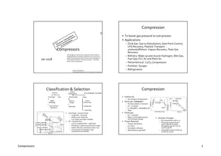
- 1. Compressors 1 Compressors Jan 2018 RecommendedReading GPSA Engg Databook, Section 13, Compressorsand Expanders “Knowledge as to how process equipment really functions is disappearing from the process industries.This is not only my opinion,but the general view of senior technical managers, in many large corporations”,Norman Lieberman, ‘A Working Guide to Process Equipment’ Compression • To boost gas pressure to suit process • Applications – Oil & Gas: Gas to Dehydration, Dew Point Control, LPG Recovery, Pipeline Transport - onshore/offshore. Vapour Recovery. Flare Gas Recovery – Refinery: Make up and recycle Hydrogen, Wet Gas, Fuel Gas, FCC Air and Plant Air – Petrochemical: C2/C3 Compression – Fertilizer: Syngas – Refrigeration Classification & Selection Dynamic Centrifugal Single/ Multistage Horiz/ Vertical Split Barrel Axial Positive Displacement Reciprocating Piston or Plunger Diaphragm Rotary Screw / Helical Lobe Sliding Vane Liquid Ring • Centrifugal - Constant head – Large flow ~ low head – Widely used. Preferred – Low Capex and Opex. Reliable • PD - Constant Flow – Low or moderate flow ~ high head – Flexibility in capacity and pressure range – Higher efficiency and lower power cost – Less sensitive to changes in gas composition and density Centrifugal Single Stage Rotary Screw Axial Flow Head Recip - Single Stage Rotary - Liquid Ring Rotary - Straight Lobe Rotary - Sliding Vane Fans & Blowers Excluded Compression • Isothermal – No change in temperature • Isentropic “adiabatic” – No heat added or removed – pvk = constant – k = MCp/MCv = MCp/(MCp-R) – Ideal • Polytropic – pvn = constant – Real or irreversible process with entropy change • Power Required – Simple calculations – p-h chart – Simulation software – With efficiency get BHP • Number of stages – By compression ratio 3~4 – Discharge temperature < 150°C (300°F) to avoid damaging lube oil. For H2 120°C (250°F) – Interstage pressure drop 35- 70 kPa (5-10 psi) Volume v1,p1 p2 Isothermal Isentropic Polytropic Pressure Centrifugal Recip Axial Inlet Volume Flow Pressure
- 2. Compressors 2 Centrifugal Compressor • Centrifugal – Gas sucked and accelerated by rotating impeller/ vane – Stationary Diffuser/blades convert velocity head to static pressure – Multi wheel for large inlet volume flow; otherwise single wheel • Characteristic: Constant head – High flow ~ low heads – Flow reduces with higher backpressure – Multistage for high discharge pressure • Inlet guide vanes distribute gas to first stage impeller • Impeller accelerates gas, imparting kinetic energy • Diffusers change kinetic energy to pressure • Casing return bends direct gas to the next impeller • Note: Impellers getting smaller as gas volume reduces • Dry Gas seals avoid process gas leak to atmosphere Drive Shaft Bearing Impeller Diffusers Gas Seals Open, semi open or closed impeller Axial Compressor • High flow - low head – Air compressor. Gas turbine air compressor – Axial flow. Stationary vanes direct gas to next row of rotating blades – Low head/ stage – Twice no of stages than in centrifugal Centrifugal Compressor • Design Info – Flow and Suction/ Discharge Conditions. To API Std 617 – Molecular Weight changes. Sizing based on low mol weight. Hi volume • For the same head, higher Molecular Weight means higher pressure • Capacity & Head – Impeller diameter ~ speed • Affinity law – Flow α speed N, dia d – Head α N² or d² – Power α N³ or d³ • Single Speed Drive. Constant head – Head curve -Theoretically straight line • Less due to internal losses • Gradually reducing • Flow decided by intersection of head and system resistance curves 80 100 120 60 25 50 75 100 125 Capacity, % Head % 100% N Drooping Unstable System Resistance - Closed Loop ∆P=Flow² Plant air compressors are Recip or Screw. Do you know why? • Capacity usually low. Capacity smaller impeller dia. To get 10 bar discharge pressure, impeller tip velocity or compressor speed has to be very high • With hi capacity + integral Air Separation units, centrifugal compressors are used Centrifugal Compressor • Variable Speed Drive – Constant capacity at variable pressure or variable capacity at constant pressure or variable capacity and variable pressure – Speed changed to suit process flow and pressure condition within driver + compressor limits – Flow decided by intersection of head and system resistance curves 80 100 120 60 25 50 75 100 125 Capacity, % Head % 105% N 100% N 95% N System Resistance - Closed Loop ∆P=Flow²
- 3. Compressors 3 Centrifugal Compressor • Surge – At surge point, developed head < system resistance – Discharge gas flows back – As flow drops, discharge pressure drops and compressor resumes forward flow – Cycle is repeated. Large pressure and flow fluctuation – Machinery damage. Thrust bearing affected due to rotor shifting back and forth • Stonewall or choked flow – At high flow - low head (low system resistance) gas may reach sonic velocity – For a given gas, maximum flow reached • Interstage Cooling – Head and Power αT1 – Interstage cooling, allows lower temperature to next wheel inside stage/ next stage – Internal cooling • Water cooling through jackets in diffuser diaphragms • Liquid injection in return channels. In refrigeration units – External cooling Energy saved with interstage cooling Pressure P2 P1 Volume V2 V1 Compressor Surging Video Shaft Seals • Oil or gas seals. Eliminate process gas leak along shaft to atmosphere • Injected at a pressure marginally higher than process between 2 sleeves. Gap between sleeves 5 microns • Seal gas flows towards process and atmosphere presenting a barrier to direct passage of process gas • A separation or buffer gas (air or inert gas) used if seal gas is process gas Red = Rotating Yellow = Stationary Seal Gas Leak Separation Gas Process Single Gas Seal Inner Seal Seal Separation Seal Leak Buffer Gas Double Gas Seal Seal Gas Separation Gas Inner Seal Inboard Seal Separation Seal Outboard Seal Py Seal Leak Seal Gas Separation Gas Tandem Gas Seal Sy Seal Leak Inner Laby Primary Seal Separation Seal Secondary Seal Lube & Seal Oil System • Lubrication oil for bearings • Older compressors have seal oil • Combined lube and seal oil system – With booster pumps for seal • Separate lube and seal oil system for contaminated gas • Buffer gas injection to form a barrier between process gas and seal oil • Degassing tank: in seal oil return line to remove oil-entrained gas • Outer sleeve seal oil returned via atmospheric drain system • Inner sleeve seal oil returned or discarded if contamination by process gas • Overhead run down tank provides 15 minutes of seal oil for compressor coastdown after a trip Lube & Seal Oil Buffer Gas Seal Oil Lube Oil Carbon Seal Shaft Bearing Process Seal Oil & Buffer Gas Caution Seal Gas: • Good filter as gap between sleeve faces 5 μ • Seal gas superheating may be required • Saturated process gas is known to drop out heavy condensate while cooling after a shutdown and damage the seals Positive Displacement - Reciprocating • Piston or Plunger – Constant flow in each stroke – Single or multistage • Diaphragm – Flexible diaphragm • Characteristic: Constant flow – Can compress against any head – Lubricated/ non-lubricated • Non-lubricated in air and O2 service – Interstage coolers – Compressor and outlet piping will be damaged with closed outlet. PSV required Integral Engine Compressor (Compressor Driven By Gas Engine) Suction Discharge Clearance Pocket • Cooled and Lubricated Cylinder • Lubricated Packing Case • Dry Liner on cylinder Inner Wall • Pistons may have Teflon Wear Rings • Double acting pistons in LP Stage • Single Acting in LP Packing case Double Acting Piston Video
- 4. Compressors 4 Recip Compressors • To API Std 618 • “Pulsating” on each suction stroke - from no flow to filling • Pulsation dampeners on suction and discharge – For smooth flow and to avoid vibration – Limit peak to 2% of average pressure – Analog studies done • Startup Unloading. Manual/ automatic – Discharge venting – Discharge to suction bypass – Inlet valves kept open with valve lifters • Capacity Control Constant volume flow – On-off, based on discharge pressure – Variable Displacement: Inlet valve/ Clearance unloading 100, 75, 50, 25, 0% – Variable speed drive or transmission Screw & Sliding Vane Compressor Sliding Vane • Eccentrically mounted rotor. Sliding Vanes • Gas trapped and pushed by vanes – Vapor Recovery & Vacuum Service Screw/ Helical lobe • Intermeshed rotors – Progressively reducing interlobe spacing compresses gas – Air and Refrigeration services – Capacity control by a slide valve ~ 10-100% • To API Std 619 Liquid Ring Compressor • Vacuum pump • Eccentrically mounted rotor • Vanes churn liquid, typically water • Liquid ring seals spaces between vanes - compression chambers of reducing volume – Make-up filtered liquid – Liquid acts as a coolant • Good for wet, saturated, dirty, toxic, explosive and corrosive gases – H2S, Dry and Wet Chlorine, H2, VCM • Ideal for gases with liquids, dust and dirt - flare gas recovery Hyper Compressor • High-pressure recip compressor for LDPE (Low Density Polyethylene) plants • Ethylene to 3,500 bar (50,000 psia) From: https://www.burckhardtcompression.com/ Separator Extruder PE Pellets Reactor Hyper Compressor Booster Compressor C2 =Storage
- 5. Compressors 5 Compressor Performance • Isentropic Performance – Head His = ZavRT1/(M(k-1)/k)*[(P2/P1)(k-1)/k-1] – k = Cp/Cv – Power, Pgas = w.His/(ηis*CF) w = kg/s or lb/min CF = 1,000 SI or 33,000 FPS – T2 = T1 + {T1*[(P2/P1)(k-1)/k-1]}/ηis • Polytropic Performance – Replace k with n – n/(n-1) = k/(k-1)*ηp – T2 = T1*(P2/P1)(n-1)/n – BHP = Pgas + Mechanical Losses towards bearing/ gear @ Pgas 0.4 P1 Enthalpy Pressure P2 Entropy Lines 1 2 2’ Temp Lines ∆his ∆h Head/ Enthalpy Change from p-h Dgm ηp = 0.7-0.85 based on flow/ BHP Compressor Sizing Calc Compressor Drives • Electrical Motors – Constant speed – Variable speed drive VSD • Variable Speed – Internal combustion engines – Gas turbines • Power delivery based on ambient temperature. Can load more during nights and in winter – Steam turbines – Turbo Expanders • Common driver for 2 separate compressors • N+1 compressors – Lead/ lag control – Base load/ swing load Compressor Control • Controls – Affinity law: Q α N. H α N². HP α N³ – On reducing flow, speed is reduced or suction is throttled to maintain inlet flow away from surge. On further reduction ASV, anti-surge valve opens to recycle discharge flow to suction – Suction pressure with an override from discharge pressure to control variable speed drives – Suction or discharge throttling or inlet guide vanes in fixed speed drivers – Anti-surge protection via recycle back to suction – Hot gas bypass to suction for anti-surge protection during coastdown PIC PIC SC Speed Control GT PIC M PCV Instead of speed, % throttling Instead of PC, FC can be used 80 100 120 60 25 50 75 100 125 Capacity, % Head % 105% N 100% N 95% N Compressor Control Compressor Surge Control Video Inlet flow measurement and operating speed decide approach to surge and Anti Surge Valve is opened to increase inlet flow For seal oil / fire case/ reduce start-up load BDV is opened PAHH PALL PAH PAL LAHH LALL LAH LIC LAL LG LV Suction Scrubber Discharge Cooler PIC PCV FCV PG TG PG TG PAHH PALL TAHH PALL TAHH FIC PAH PAL PIC SC ASC Anti Surge Valve Compressor Speed Control Compressor Surge Control To Flare Hot gas Bypass Bearing - Vibration, Shaft - Axial Movement Temperature Trips To Flare RO BDV FAH FAL LO PSV LO PSV
- 6. Compressors 6 Compressor Protection • Low suction pressure d/s of suction filter. Very commonfor suction filter to get plugged with debris and mill scale • High discharge pressure/temperature • Anti-surge* • Vibrations • High temperature of bearings • High axial movement • Lube oil/ Seal failure • Suction KOD – High level trip • Piping from KOD to compressor heat traced /sloped to KOD • Suction side designed to settle out pressure = (VsPs+VdPd)/(Vs+Vd) • Discharge PSV • API 14 C – Compressor Unit Compressor Settle Out Calc * Dynamic Simulation Studies • Close inlet SDV – ASV and suctionPCV response.Suction PALL set point.SDV closure time • Close outlet SDV – ASV response. Discharge PAHH set point. SDV closure time • Fail open ASV – Compressorcontrols response • Trip one or both compressors – CheckASV Cv – Hot gas bypass requirement Some systems may have inlet coolers Operational Issues • Centrifugal – High discharge resistance – Dirt or coke buildup on rotor or diffusers – Changes to gas mol wt – Poor surge control response. Hot bypass required • PD Compressors – Dirt or liquid – Poor adjustments. Coolant and lube oil – Leaking suction/ discharge valves • Safety Alert – Poor min flow recycle resulted in vacuum in suction, pulling in air. On compression air:HC exploded – Vibration in compressor outlet piping. 1/4" bolt on local TG support, cut thru pipe, releasing H2. During plant walk about check and avoid sharp objects close to piping Thank You