Downloaded 417 times
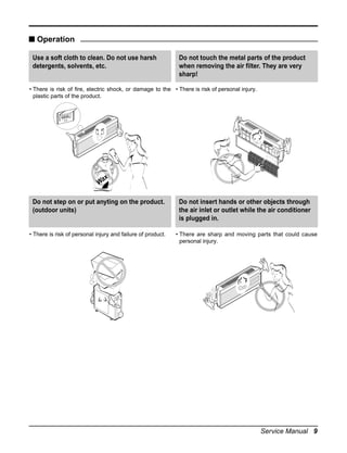
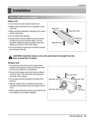
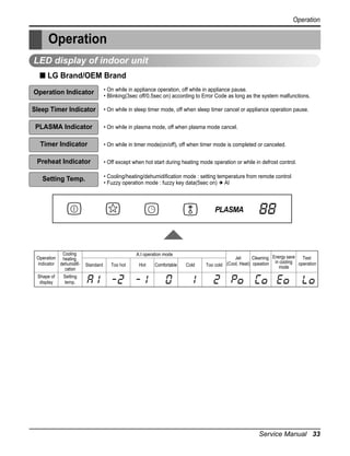
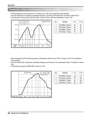
![Operation
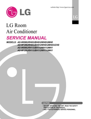
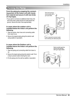
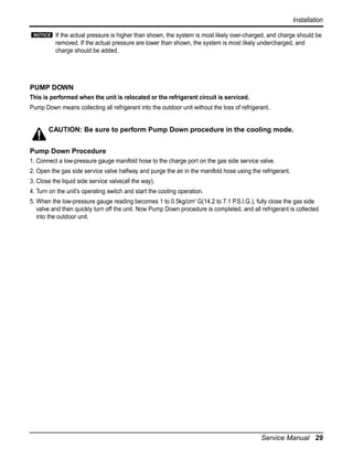
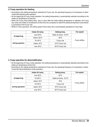
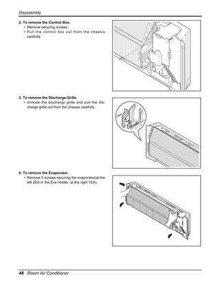
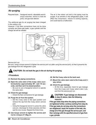
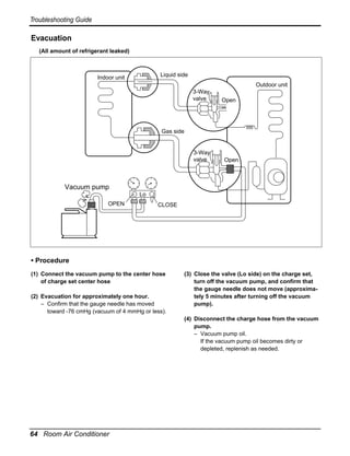
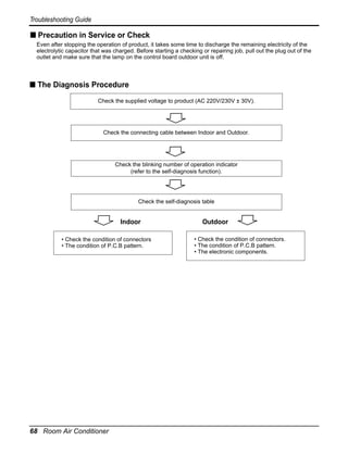
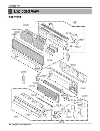
Cooling mode operation
• Operating frequency of compressor depend on the difference of the temperature.
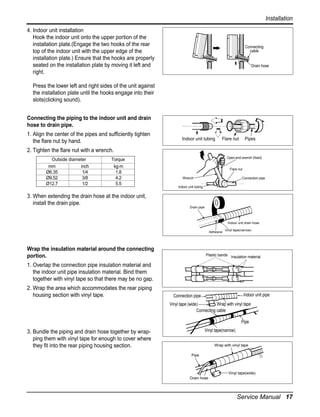
(= intake air Temp.- Compressor off Temp.
• Compressor off temp.= setting temp. -0.5°C
on temp. = setting temp. +0.5°C
• If compressor operates at some operating frequency, the operating frequency of compressor cannot be
changed within 30 seconds.
• Condition of compressor turned off
- When intake air temperature stay at the temperature between setting temp. -0.5°C and setting temp.
-1.0°C for 3 minutes continuously.
- When intake air temperature reaches below the temperature of setting temp. -1.0°C.
• Compressor 2 minutes delay
- The compressor can restart minimum 2 minutes later after compressor off.
[The operating freq. step of comp.]
Temp. differences
Comp. Operating frequency
over 3.0°C
Step 7
over 2.5°C
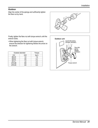
Step 6
2.0~2.49°C
Step 5
1.5~1.99°C
Step 4
1.0~1.49°C
Step 3
0.5~0.99°C
Step 2
0.0~0.49°C
Step 1
[The targeting operating freq. of comp. each model]
Model
Comp. Operating frequency
Step 3
Step 4 Step 5(Fc)
Step 1
Step 2
Step 6
Step 7
AS-W096U_0 Series
15
23
31
38
47
58
65
AS-W126U_0 Series
15
25
35
46
58
61
66
AS-W096U_1 Series
20
35
40
48
53
58
62
AS-W126U_1 Series
20
35
45
57
69
77
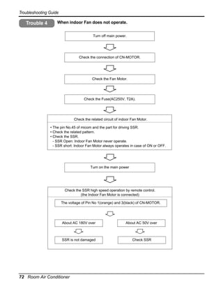
86
Service Manual 35](https://image.slidesharecdn.com/artcoolmirrorsu-chassis-servicemanual-140223043103-phpapp01/85/Artcool-mirror-su_chassis-service-manual-35-320.jpg)
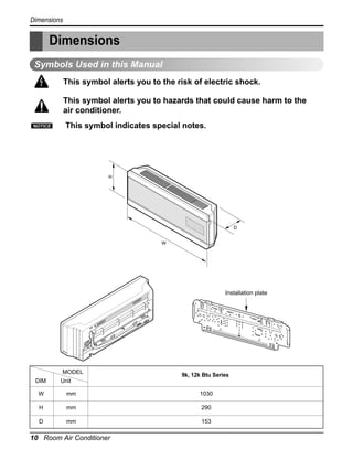
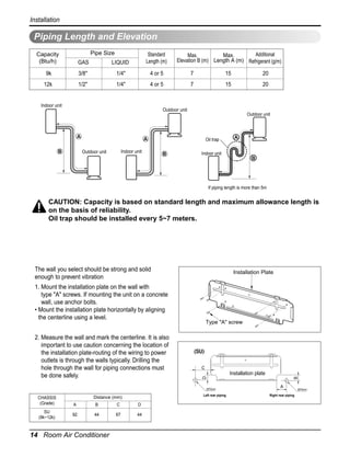
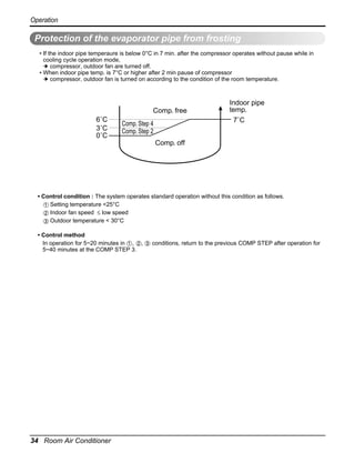
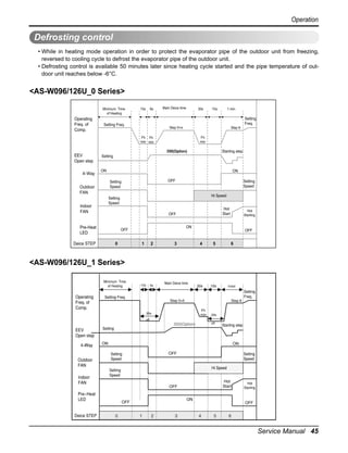
![Operation
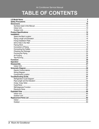
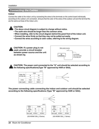
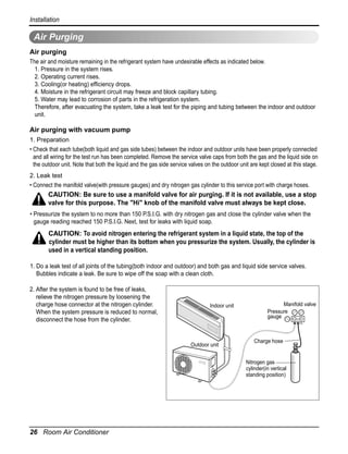
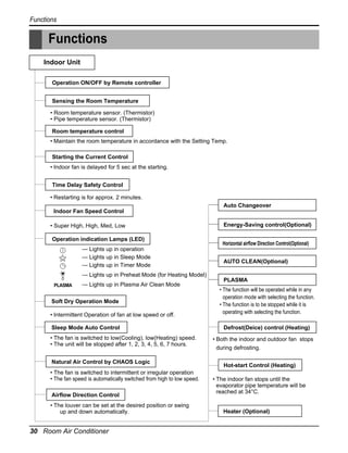
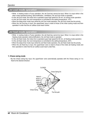
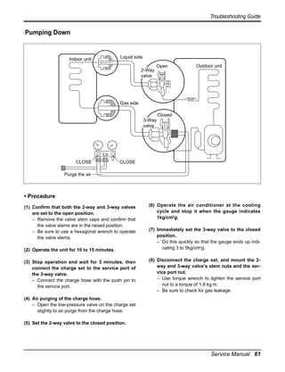
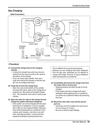
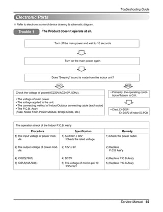
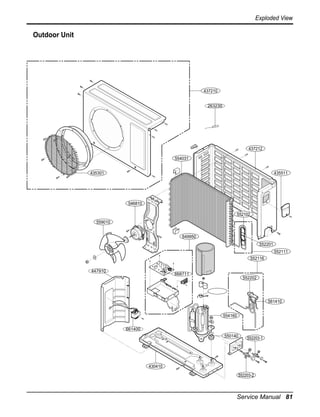
Heating mode operation
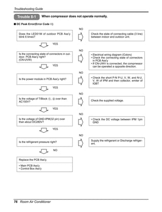
• Operating frequency of compressor depend on the difference of the temperature
(= compressor off temp. - intake air temp.)
• Compressor off temp. = setting temp.+3.0°C
on temp. = setting temp.
• If compressor operates at some operation frequency, the operating frequency of compressor cannot be
changed within 30 seconds.
• Condition of compressor turned off
- When intake air temperature reaches +3°C above the setting temperature.
• Condition of indoor fan turned off
- While in compressor on:indoor pipe temp. < 30°C
• While in defrost control, between the indoor and outdoor fans are turned off.
• Compressor 2minutes delay
- After compressor off, the compressor can restart minimum 2 minutes later.
[ The operating freq. step of comp]
Temp. differences
Comp. Operating frequency
over 3.0°C
Step 7
2.5~3.0°C
Step 6
2.0~2.49°C
Step 5
1.5~1.99°C
Step 4
1.0~1.49°C
Step 3
0.5~0.99°C
Step 2
0.0~0.49°C
Step 1
[The targeting operating freq. of comp. each model]
Model
Comp. Operating frequency
Step 3
Step 4 Step 5(Fc)
Step 1
Step 2
Step 6
Step 7
AS-W096U_0 Series
15
29
39
49
59
66
73
AS-W126U_0 Series
25
31
40
52
68
71
73
AS-W096U_1 Series
20
35
48
58
67
75
87
AS-W126U_1 Series
20
35
48
62
82
86
89
Service Manual 37](https://image.slidesharecdn.com/artcoolmirrorsu-chassis-servicemanual-140223043103-phpapp01/85/Artcool-mirror-su_chassis-service-manual-37-320.jpg)
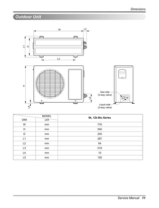
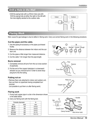
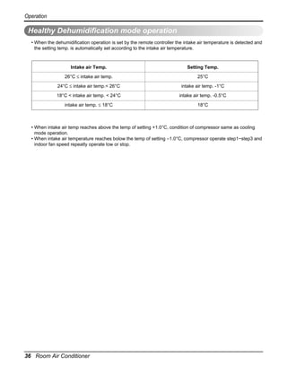
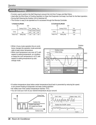
![Operation
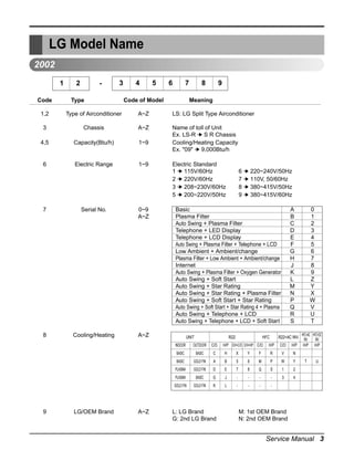
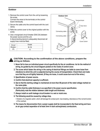
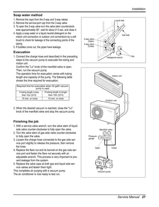
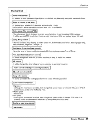
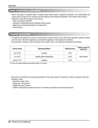
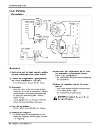
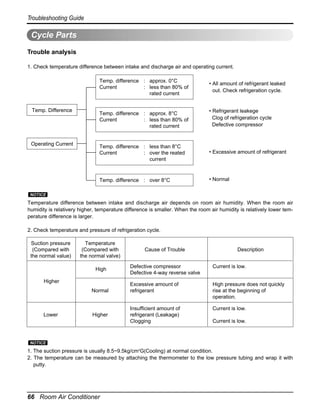
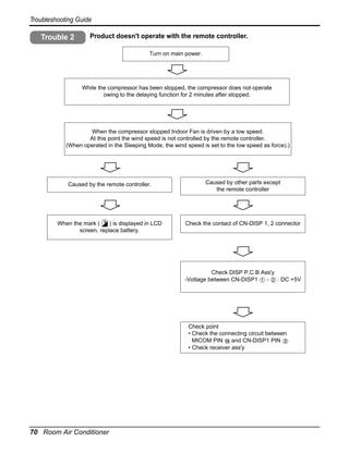
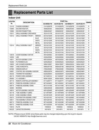
Sleep timer operation
• When the sleep time is reached after [1,2,3,4,5,6,7hr] is input by the remote control during the operation, the
operation of the appliance stops.
• When the appliance is on pause, the sleep timer mode cannot be input.
1. Sleep timer operation for cooling cycle
• While in cooling mode operation, 30 min. later since the start of the sleep timer, the setting temperature
increase by 1°C. After another 30min. elapse, it increases by 1°C again.
Setting temp. (˚C)
1.0˚C up
1.0˚C up
Cooling ON temp.
(Setting temp. +0.5˚C)
Cooling OFF temp.
(Setting temp. -0.5˚C)
0.5
1
Sleep time (hr)
2. Sleep timer operation for heating cycle
• While in heating mode operation, 60 min. later since the start of the sleep timer, the setting temperature
decrease by 1°C. After another 60min. elapse, it decreases by 1°C again.
Setting temp. (°C)
Heating OFF temp.
(Setting temp. +3.0°C)
1.0°C down
1.0°C down
Heating ON temp.
(Setting temp)
1
2
Sleep time (hr)
Service Manual 41](https://image.slidesharecdn.com/artcoolmirrorsu-chassis-servicemanual-140223043103-phpapp01/85/Artcool-mirror-su_chassis-service-manual-41-320.jpg)
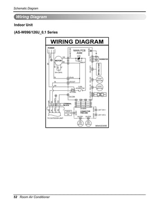
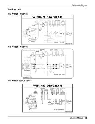
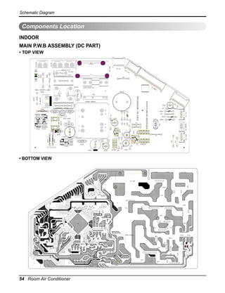
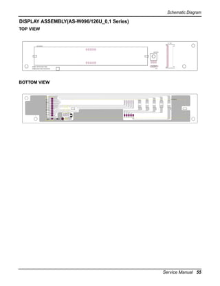
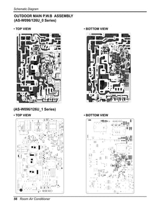
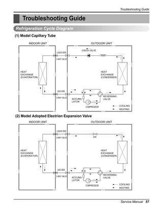
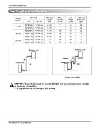
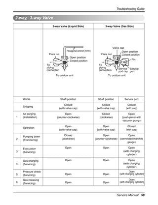

This document provides product specifications and installation/operation manuals for LG room air conditioner models AS-W096U_0, AS-W126U_0, AS-W096U_1, and AS-W126U_1. It includes details on dimensions, cooling/heating capacities, electrical specifications, installation instructions, functions, troubleshooting guides, diagrams and exploded views. Safety precautions for installation and use are provided at the beginning.


![K-12 Module in TLE - ICT Grade 10 [All Gradings]](https://cdn.slidesharecdn.com/ss_thumbnails/grade10-tle-ict-chs-lm-160617105039-thumbnail.jpg?width=640&height=640&fit=bounds)


