Downloaded 149 times


![Performing leak tests
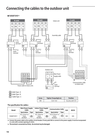
A RJ040F2HX**/
RJ050F2HX**
PUMP DOWN (before disconnecing t the refrigerant connections for unit repair,
removal or disposal)
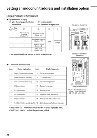
Pump-down is an operation intended to collect all the system refrigerant in the outdoor unit. A
This operation must be carried out before disconnecting the refrigerant pipe in order to avoid
refrigerant loss to the atmosphere.
- Shut off all the liquid valve with the Allen wrench.
- Turn the system on in cooling with fan operating at high velocity. RJ060F3HX**
(Compressor will immediately start, provided 3 minutes have elapsed since the last stop).
- After 2 minutes of operation, shut down the suction valves with the same wrench.
- Turn the system off and switch mains supply off.
- Disconnect pipes. After disconnection, protect valves and tubing ends from dust.
- Compressor damage may occur if run at a negative suction pressure. A
B
C
RJ070F4HX**/
※ The designs and shape are subject to change according to the model. RJ080F4HX**
A
B
C
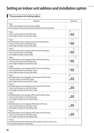
Pipe installation with indoor units
◆ RJ060F3HX**/RJ070F4HX**/RJ080F4HX**
Follow different orders depending on the capacity of indoor units. OUTDOOR UNIT
MH020/023/026/030/035F***/NJ026/035**/AQV07/09/12**
◆ Install pipes between indoor and outdoor units orderly as[A→B →C→D].
MH052F***/AQV18/24**
◆ Install pipes between indoor and outdoor units orderly as [ C→D].
Examples
◆ 2Rooms: MH035FV**+MH052FV**
A A A MH035FV**
MH035FV** MH052FV**
B
B B
MH035FV** MH052FV** A unit
C C C
MH052FV**
D D D
B unit
C unit
(o) (x) (x)
D unit
◆ 3Rooms: MH026FV**+MH035FV**+MH052FV**
A MH026FV** A MH052FV**
B B
MH035FV** MH035FV**
C C
MH052FV** MH026FV**
D D
(o) (x)
22](https://image.slidesharecdn.com/samsungfjminstallationmanual-120310140317-phpapp02/85/Samsung-fjm-installation-manual-22-320.jpg)
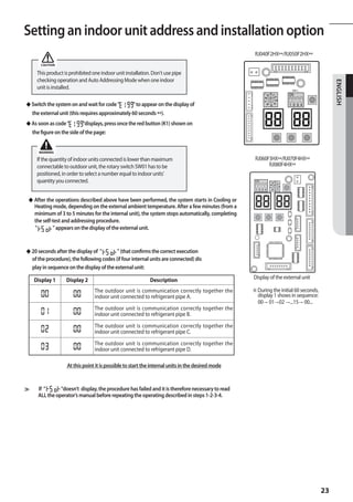
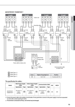
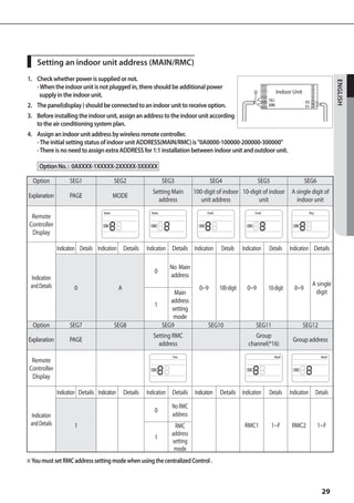
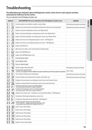
![Setting an indoor unit address and installation option
A
ROTARY SWITCH “SW02” POSITION ACCORDING TO REFRIGERANT CIRCUIT CONNECTED ( 0=A; 1=B; 2=C; 3=D )
Indoor Unit Indoor Unit
OUTDOOR UNIT OUTDOOR UNIT SW02
SW02
Att. A Att. A
0 0
A unit
Att. B A unit Att. B
1 1
B unit
B unit C unit
Att. C
2
Indoor Unit
OUTDOOR UNIT SW02
Att. A
0
Att. B
1
A unit Att. C
B unit
2
C unit
D unit
Att. D
3
INSTALLATION TEST MODE (with all indoor units functioning)
Please do cool mode try-run or heat mode try run.
Cool mode try-run : Push the [K2] button three times.
Heat mode try-run : Push the [K2] button once.
After 12 minutes of stationary condition check each indoor unit air treatment:
Cooling mode (indoor unit check) -- Inlet air temp. - Outlet air temp: From 10°K to 12°K ( indicative delta T)
Heating mode (indoor unit check) -- Outlet air temp. - Inlet air temp: From 11°K to 14°K (indicative delta T)
In heating mode, the indoor fan motor can remain off to avoid cold air blown into conditioned space.
26](https://image.slidesharecdn.com/samsungfjminstallationmanual-120310140317-phpapp02/85/Samsung-fjm-installation-manual-26-320.jpg)
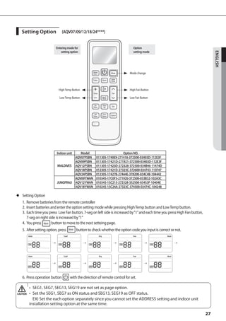


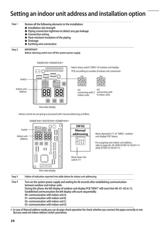
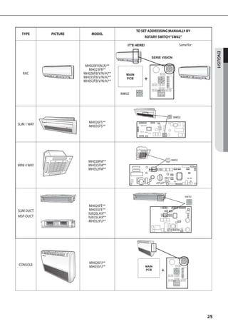
This document provides instructions for installing an air conditioner. It discusses: 1. Safety precautions that must be followed such as always disconnecting power before servicing and ensuring qualified personnel perform installation. 2. Factors to consider when deciding where to install the outdoor unit such as allowing sufficient clearances and avoiding direct sunlight. 3. Details on installing the drain hose, cutting piping, connecting cables, and other assembly steps. Diagrams show piping layouts and limitations on line lengths. 4. Procedures for leak testing, purging the circuit, adding refrigerant and other tests. Instructions are provided for indoor unit installation and settings. 5. Troubleshooting


