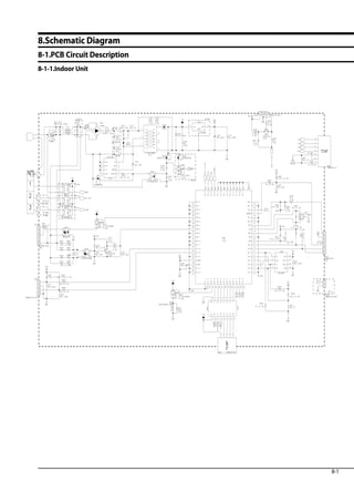
This document provides specifications and operating instructions for a Samsung split-type air conditioner model AQ07TSBNSER. It includes:
1. Precautions for servicing, static electricity, and safety.
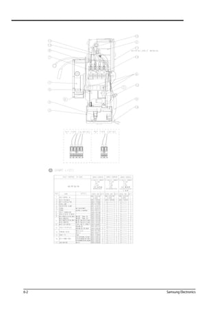
2. Product specifications including features, comparative specs, accessories, filters and operation properties.
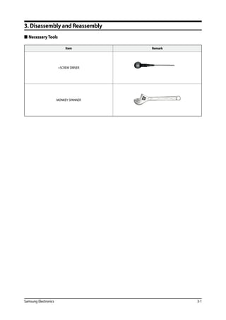
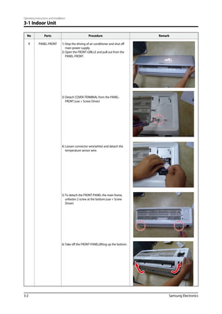
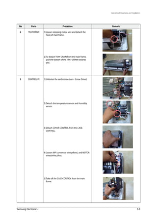
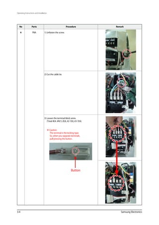
3. Instructions for disassembly and reassembly of the indoor and outdoor units.
4. Troubleshooting including error display, diagnosis by symptoms, PCB inspection, and main part inspection.

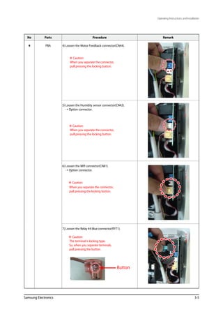
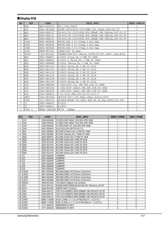
![4-8 Samsung Electronics
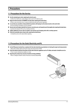
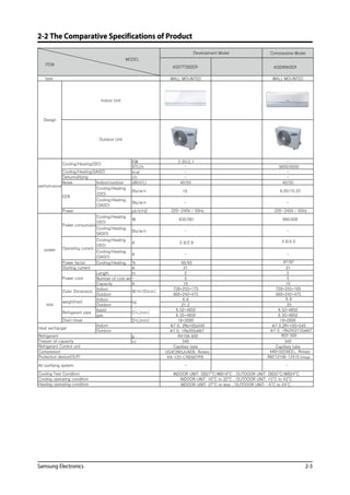
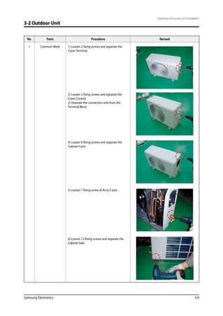
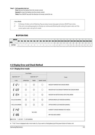
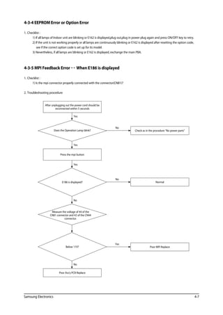
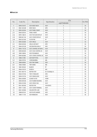
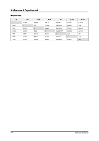
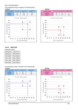
4-3-6 No Power (completely dead)-Initial diagnosis (Not displayed)
1. Checklist :
1) Is input voltage normal?
2) Is AC power linked correctly?
3) Is input voltage of DC regulator IC KA7805 (IC02) normal? (11VDC-12.5VDC)
4) Is output voltage of DC regulator IC KA7805 (IC02) normal? (4.5VDC-5.5VDC)
2. Troubleshooting procedure
PCB should be replaced
No
Replace fuse
No
Reconnect wires correctly
No
Check the display board
operate
Press the
Power Button on the
remote control unit to operate the
air conditioner
Unplug the power cord and
plug it after 30 seconds
Check the indoor unit
control board
does not operate
Check whether
2 wires of power cord are
connected correctly to the
terminal block and
control board.
Check whether
the fuse on the control board is normal.
FUSE(F701) : T3.15[A]/250[V] or
T2.5[A]/250[V]
Check the output of
SMPS on the control board.
Input power: AC230±15%[V]
IC02 Input: DC12[V]
IC02 output: DC5[V]
Check the setting temperature
Yes
Yes
Yes
Yes](https://image.slidesharecdn.com/smaq07tsbnsereng-191219085717/85/Sm-aq07-tsbnser-eng-29-320.jpg)
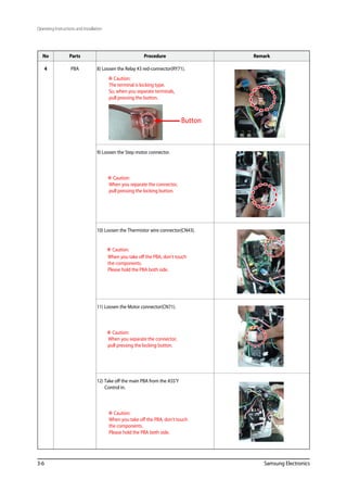
![4-10 Samsung Electronics
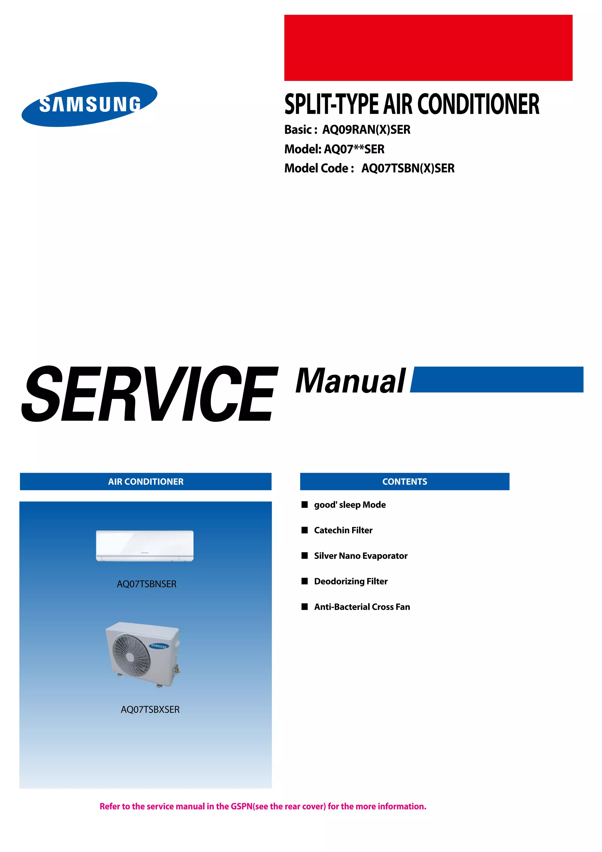
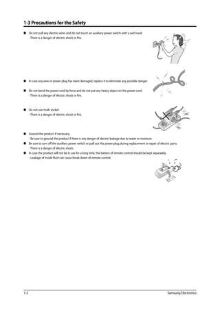
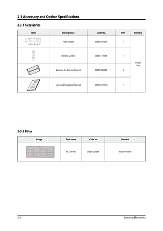
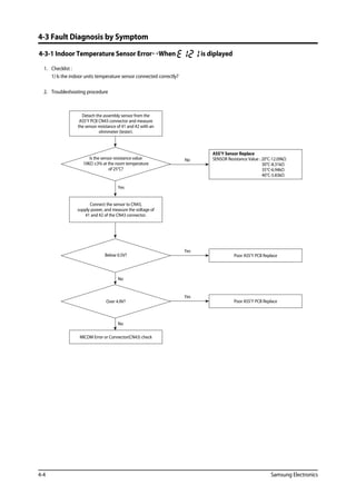
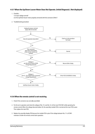
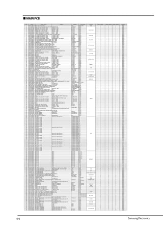
4-4 PCB Inspection Method
4-4-1 Pre-inspection Notices
1. Check if you pulled out the AC power plug when you eliminate the PCB or front panel.
2. Don’t hold the PCB side not impose excessive force on it to eliminate the PCB.
3. Don’t pull the lead wire but hold the whole housing to connect or disconnect a connector to the PCB.
4-4-2 Inspection Procedure
1. Check connector connection and peeling of PCB or bronze coating pattern when you think the PCB is broken.
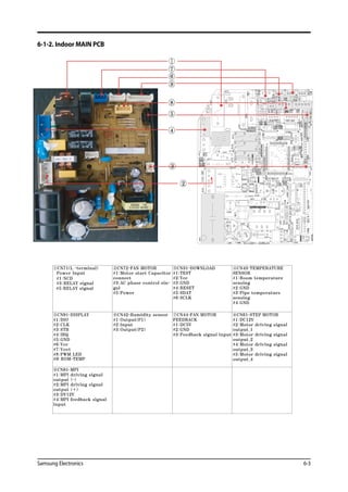
2. The PCB is composed of the 2 parts.
1. Indoor Main PCB Part : MICOM and surrounding circuit, relay, room fan motor driving circuit and control circuit, sensor driving
circuit, power circuit of DC12V and DC5V, and buzzer driving circuit.
1. Display part : LED lamp, Switch, Remocon module
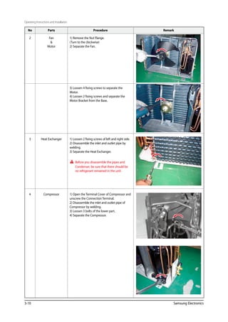
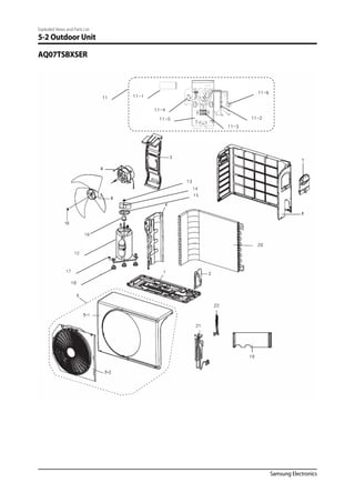
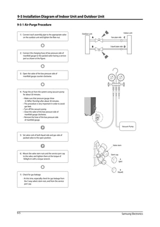
4-4-3 Indoor Detailed Inspection Procedure
No Procedure Inspection Method Cause
1 Plug out and pull the PCB
out of the electronic box.
Check the PCB fuse.
1) Is the fuse disconnected? • Over current
• Indoor Fan Motor Short
• AC Part Pattern Short of the MAIN PCB
2 Supply power.
If the operating lamp
twinkles at this time,
the above 1)~3) have
no relation.
Checking the power voltage.
1) Is the BD71 input voltage AC200V~AC240V? • Power Cord is fault, Fuse open. Wrong Power
Cable Wiring, AC Part is faulty.
2) Is the voltage between both terminals of the
C109 on the 2 side of the transformer DC12V ±0.5V?
• Switching Trans or Power Circuit is faulty
3) Is the voltage between both terminals of OUT
and GND of IC02(KA7805) DC5V ±0.5V?
• Power Circuit is faulty, Load Short
3 Press the ON/OFF button. Checking the power voltage.
1) Is the voltage over AC180V being imposed on
1) terminal #3 and #5 of the fan motor
connector(CN72)?
• Fan Motor of the indoor is faulty
2) Check the voltage of both terminals of
terminal block 1 and N(1) after 3 minute
operation.: AC220V
• Relay(RY71) Contact is faulty
4 Press the ON/OFF button.
1. FAN Speed [High]
2. Continuous Operation
1) Is the voltage over AC180V being imposed on
1) terminal #3 and #5 of the fan motor
connector(CN72)?
• Fan Motor of the indoor is faulty
2) The fan motor of the indoor unit doesn’t run. • Fan Motor Connector(CN72) is faulty
3) The power voltage between terminal #3 and #5
of the connector(CN72) is 0V.
• ASS’Y Main PCB is faulty
• Connection is faulty](https://image.slidesharecdn.com/smaq07tsbnsereng-191219085717/85/Sm-aq07-tsbnser-eng-31-320.jpg)
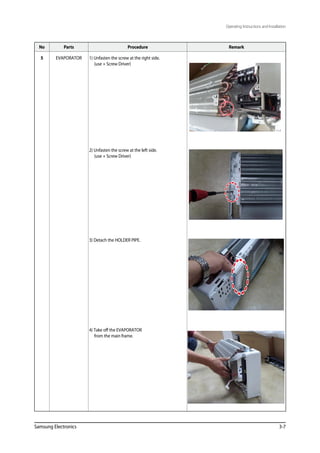
![Samsung Electronics
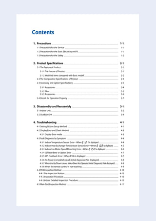
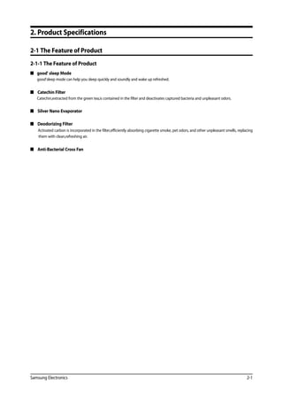
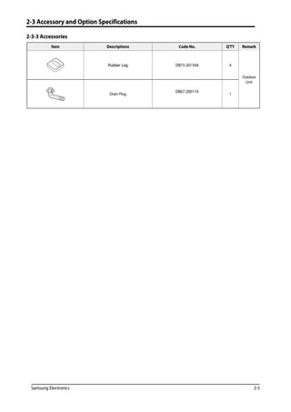
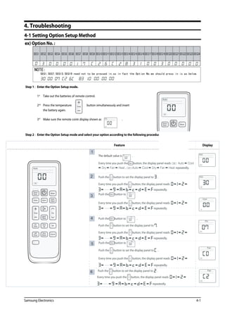
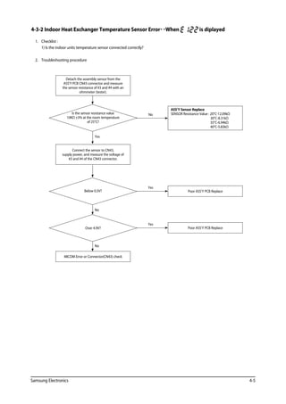
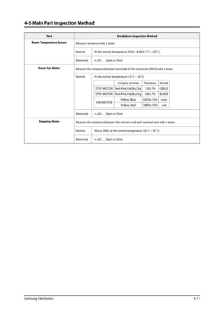
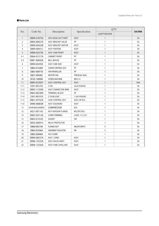
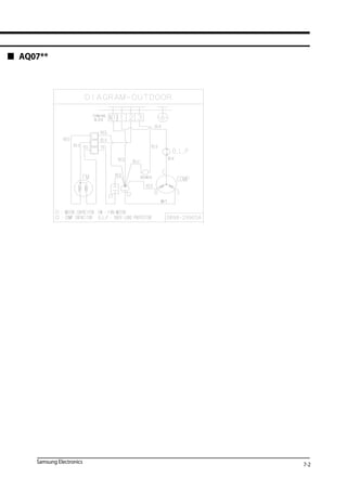
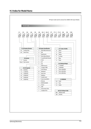
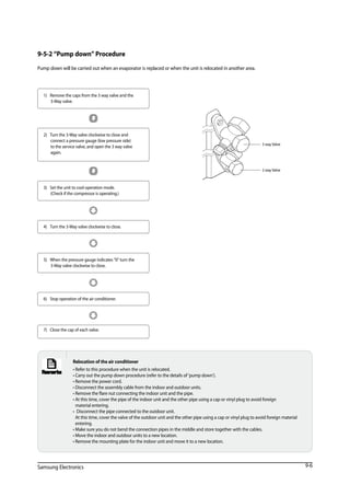
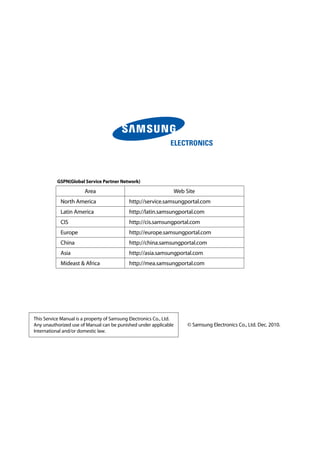
9-4 Low Refrigerant Pressure Distribution
Note : • Please measure the refrigerant pressure after the air conditioner operates on testing cooling mode during more than
10 minutes.
□ Indoor Temp. Variation : 21°C ~ 32°C
□ Outdoor Temp. Variation : 20°C ~ 45°C
3.5
4
4.5
5
5.5
6
6.5
20 25 30 35 40 45
Outdoor temperature[℃]
Ps[fgk/㎠]
Indoor temperature
21℃
27℃
32℃
3.5
4
4.5
5
5.5
6
6.5
20 25 30 35 40 45
Outdoor temperature[℃]
/fgk[sP㎠]
Indoor temperature
21℃
27℃
32℃
3.5
4
4.5
5
5.5
6
6.5
20 25 30 35 40 45
Outdoor temperature[℃]
f/gPs[k㎠]
Indoor temperature
21℃
27℃
32℃
3.5
4
4.5
5
5.5
6
6.5
20 25 30 35 40 45
Outdoor temperature[℃]
Ps[kgf/㎠]
Indoor temperature
21℃
27℃
32℃
**09**
**12**
**18**
**24**
9-4](https://image.slidesharecdn.com/smaq07tsbnsereng-191219085717/85/Sm-aq07-tsbnser-eng-51-320.jpg)


![Yammar manual tk486_v,_tk486e[1]](https://cdn.slidesharecdn.com/ss_thumbnails/yammarmanualtk486vtk486e1-201015200004-thumbnail.jpg?width=640&height=640&fit=bounds)