The document discusses code for independently flashing 3 LEDs with different on and off periods using an Arduino Uno board. The author has set up the hardware with 3 LEDs connected to digital pins 6, 7 and 8. Their code currently causes all LEDs to flash with the same on/off period rather than independently. They are seeking help altering their code to independently control the on and off periods of each LED. Several suggestions are provided, including using external interrupts triggered by a separate pin and counting interrupts to control the LED timing. However, the author is still struggling to get the LEDs flashing independently as intended.
![Arduino - multiple LEDs with differentdelays
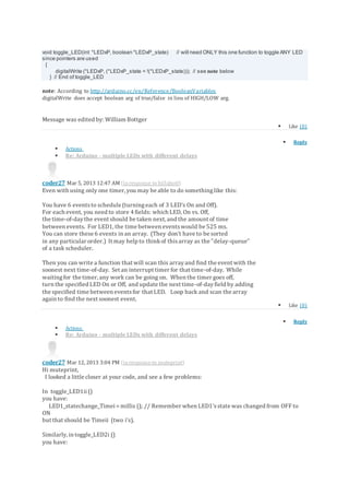
muteprint Mar 4, 2013 1:56 AM
Hi all
I'm tryingto write code to get 3 LEDs flashing independently, each with a different ON and OFF
period.
For example:
LED1: ON for 25 ms, OFF for 500 ms
LED2: ON for 50 ms, OFF for 800 ms
LED3: ON fo 100 ms, OFF for 300 ms
So far I have set up the hardware: 3 LEDs on digital pins6, 7 and 8 using myArduino UNOboard and
a breadboard.
Code-wise I understand that I can't use the "delay" function because it causes the whole system to
delayi.e. causes 'blocking'. At the moment I'm using the millis() function. My problem is that at the
moment my code causes LED1 to turn ON for 25 ms and off for 25 ms, LED2 turnsON for 50 ms and
off for 50 ms etc. So I need to somehow alter the OFF period independently.
In summary: I need a new approach or an alteration to my code to be able to independentlychange
the ON and OFF periods for each of myLEDs independently.
Here is my code so far:
[code]
// Which pins are connected to which LED
const byte LED1 = 6;
const byte LED2 = 7;
const byte LED3 = 8;
// Assigningdelays.
const unsigned long LED1_interval = 25;
const unsigned long LED2_interval = 50;
const unsigned long LED3_interval = 100;
// Declaringthe variablesholdingthe timer values for each LED.
unsigned long LED1_timer;
unsigned long LED2_timer;
unsigned long LED3_timer;
// Setting3 digital pinsas output pins and resettingtimer
void setup ()
{
pinMode (LED1, OUTPUT);
pinMode (LED2, OUTPUT);](https://image.slidesharecdn.com/arduino-181117125603/85/Arduino-1-320.jpg)
![Arduino - multiple LEDs with differentdelays
muteprint Mar 4, 2013 1:56 AM
Hi all
I'm tryingto write code to get 3 LEDs flashing independently, each with a different ON and OFF
period.
For example:
LED1: ON for 25 ms, OFF for 500 ms
LED2: ON for 50 ms, OFF for 800 ms
LED3: ON fo 100 ms, OFF for 300 ms
So far I have set up the hardware: 3 LEDs on digital pins6, 7 and 8 using myArduino UNOboard and
a breadboard.
Code-wise I understand that I can't use the "delay" function because it causes the whole system to
delayi.e. causes 'blocking'. At the moment I'm using the millis() function. My problem is that at the
moment my code causes LED1 to turn ON for 25 ms and off for 25 ms, LED2 turnsON for 50 ms and
off for 50 ms etc. So I need to somehow alter the OFF period independently.
In summary: I need a new approach or an alteration to my code to be able to independentlychange
the ON and OFF periods for each of myLEDs independently.
Here is my code so far:
[code]
// Which pins are connected to which LED
const byte LED1 = 6;
const byte LED2 = 7;
const byte LED3 = 8;
// Assigningdelays.
const unsigned long LED1_interval = 25;
const unsigned long LED2_interval = 50;
const unsigned long LED3_interval = 100;
// Declaringthe variablesholdingthe timer values for each LED.
unsigned long LED1_timer;
unsigned long LED2_timer;
unsigned long LED3_timer;
// Setting3 digital pinsas output pins and resettingtimer
void setup ()
{
pinMode (LED1, OUTPUT);
pinMode (LED2, OUTPUT);](https://image.slidesharecdn.com/arduino-181117125603/75/Arduino-1-2048.jpg)
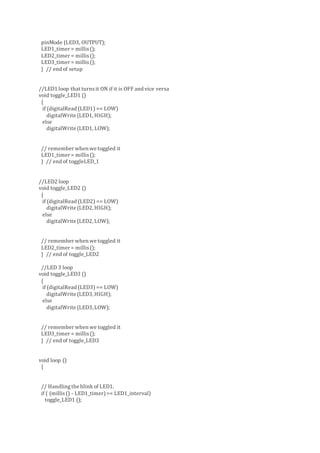
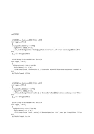
![// Handlingthe blink of LED2.
if ( (millis() - LED2_timer)>= LED2_interval)
toggle_LED2 ();
// Handlingthe blinkof LED3.
if ( (millis() - LED3_timer)>= LED3_interval)
toggle_LED3 ();
/* Other code that needsto execute goes here.
It will be called manythousand timesper second because the above code
does not wait for the LED blinkinterval to finish. */
} // end of loop
[/code]
Any help would be greatlyappreciated because I'm [b]very[/b]new to this!
Thanks!
I have the same question (0)
24908 Views
Tags:
Reply
Re: Arduino - multiple LEDs with different delays
billabott Mar 4, 2013 7:29 AM (inresponseto muteprint)
Most Arduino boards have two external interrupts: numbers 0 (on digital pin 2) and 1 (on digital pin 3).
Official Arduino.cc Example
int pin = 13;
volatile int state = LOW;
void setup()
{
pinMode(pin, OUTPUT);
attachInterrupt(0, blink, CHANGE); //0 is digtal pin 2
}
void loop()
{
digitalWrite(pin, state);
}
void blink()
{
state = !state;
}](https://image.slidesharecdn.com/arduino-181117125603/85/Arduino-3-320.jpg)
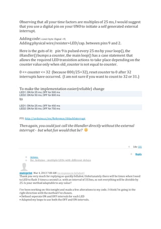
![Unfortunately I've ended gettingmyself reallyconfused and now myLEDs seem to sometimesflash
the OFF interval, sometimeswith the ON and sometimeswith a combination of the both.
Any idea how I've gone so badlywrong?
I hope I'm slowly moving in the right direction. If not I might have to try a different approach like
usingthe interupt function. I am very new to the Arduino and writingcode of any sort, so that
approach seems quite dauntingto me.
Below is myaltered code.
[code]
//DEFINING CONSTANTS& VARIABLES
// Which pinsare connected to which LED
const byte LED1 = 6;
const byte LED2 = 7;
const byte LED3 = 8;
// AssigningON and OFF interval constants.
const unsigned long LED1_ON_interval = 3000; //
const unsigned long LED1_OFF_interval = 6000;
const unsigned long LED2_ON_interval = 500; //
const unsigned long LED2_OFF_interval = 1000;
const unsigned long LED3_ON_interval = 100; //
const unsigned long LED3_OFF_interval = 3000;
// Declaringthe variablesholdingthe timer value, i.e. time of last state change.
unsigned long LED1_statechange_Timei;
unsigned long LED2_statechange_Timei;
unsigned long LED3_statechange_Timei;
unsigned long LED1_statechange_Timeii;
unsigned long LED2_statechange_Timeii;
unsigned long LED3_statechange_Timeii;
//SETUP
// Setting3 digital pinsas LED output pins and startingmillisecond timer
void setup ()
{
pinMode (LED1, OUTPUT);
pinMode (LED2, OUTPUT);
pinMode (LED3, OUTPUT);
LED1_statechange_Timei= millis();
LED2_statechange_Timei= millis();
LED3_statechange_Timei= millis();
} // end of setup](https://image.slidesharecdn.com/arduino-181117125603/85/Arduino-5-320.jpg)

![if ( (millis() - LED2_statechange_Timeii)>= LED2_OFF_interval)
toggle_LED2ii ();
//LED 3
// If the time since the last change in state from OFF to ON is equal or greater than the ON
interval
//then run the loop toggle_LED3i
if ( (millis() - LED3_statechange_Timei)>= LED3_ON_interval)
toggle_LED3i ();
// If the time since the last change in state from ON to OFF is equal or greater than the OFF
interval
//then run the loop toggle_LED2ii
if ( (millis() - LED3_statechange_Timeii)>= LED3_OFF_interval)
toggle_LED3ii ();
} // End of loop
[/code]
Thanks!
Like (0)
Reply
Actions
Re: Arduino - multiple LEDs with different delays
billabott Mar 7, 2013 1:15 PM (in responseto muteprint)
Sorry, no, I am out of ideas. I will, however, share with you that there are other uC that have multiple
timerson board that can be configured to generate interruptsat anypredetermined interval.
Q: Just out of curiosity, what exactlycontrols the periodicityof your LEDs?
Or in other words; "What isyour application, eh?"
You might simplify your program by adoptinga more conventional approach by using
boolean LED1_state = false; // place these very near the top of script so their scopes are GLOBAL
boolean LED2_state = false;
boolean LED3_state = false;
If time to turn off LED1
Set LED1_on_timer to milles()+800; // turningoff; so it is known when to turn it on again.
toggle_LED(&LED1, &LED1_state); // call function to toggle LED between 1 and 0
Set LED1_off_timer to milles() +2048; // presumeablywill be reset to a correct value
// after turningLED1 on prior to the expiration of this value
else if time to turn on LED1
Set LED1_off_timer to milles() +50; // turningon; so it is known when to turn it off again.
toggle_LED(&LED1, &LED1_state);; // call function to toggle LED between 0 and 1
Set LED1_on_timer to milles()+2048; // presumeablywill be reset to a correct value
// after turningLED1 off prior to the expiration of this value](https://image.slidesharecdn.com/arduino-181117125603/85/Arduino-8-320.jpg)