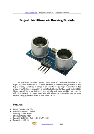
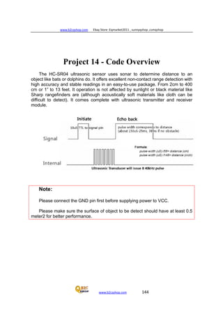
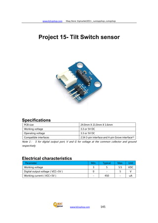
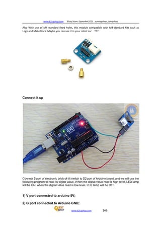
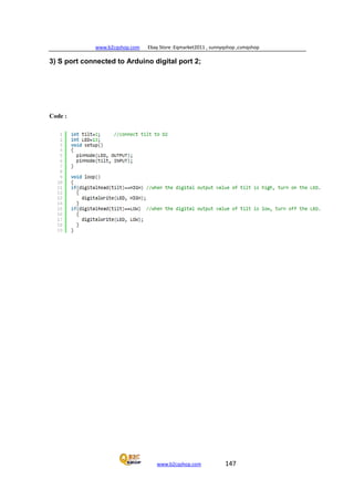
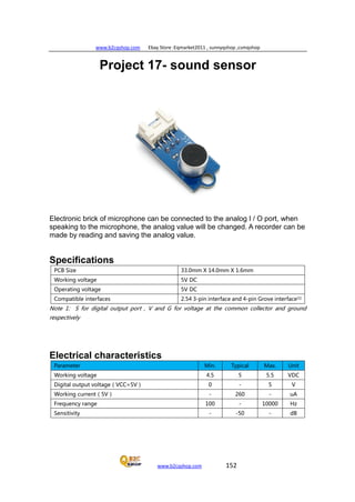
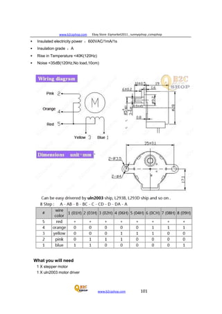
This document provides an introduction to an Arduino starter kit, including what is included in the kit and how to use the included book to learn about the Arduino hardware, software, and programming. The kit contains an Arduino Uno board, sensors, displays, and other components. The book guides the user through 16 projects of increasing complexity to teach Arduino skills. It assumes no prior knowledge and provides step-by-step instructions and diagrams to help users build each project and understand how the code and hardware work together.


![www.b2cqshop.com Ebay Store :Eqmarket2011 , sunnyqshop ,csmqshop
www.b2cqshop.com 36
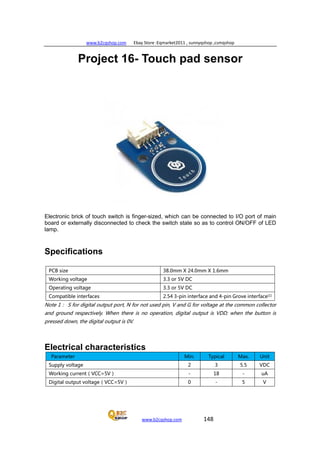
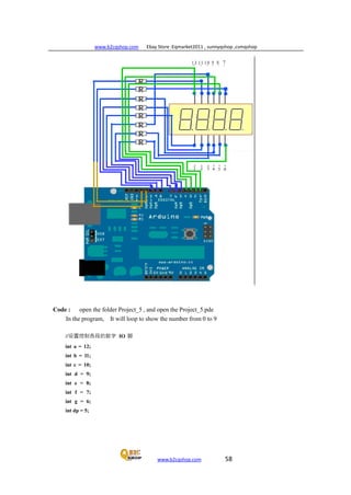
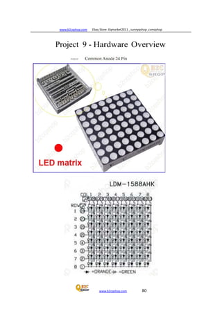
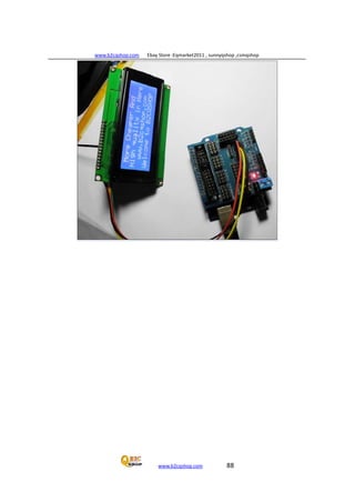
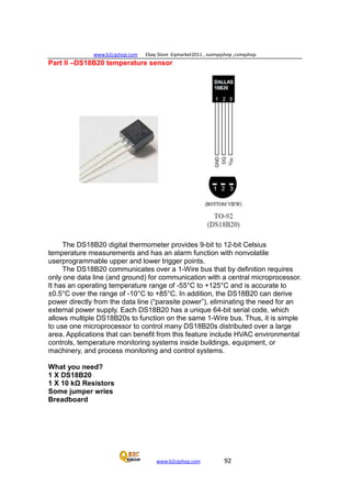
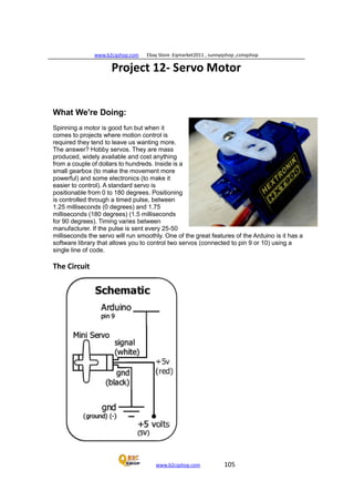
Project 3 - Serial Controlled Mood Lamp
Please check the follow picture
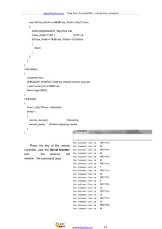
circuit, This project we will delve into
the world of serial communications
and control our lamp by sending
commands from the PC to the Arduino
using the Serial Monitor in the Arduino
IDE.
This project also introduces how
we manipulate text strings. So leave
the hardware set up the same as
before and enter the new code.
Enter the code
// Project 10 - Serial controlled
RGB Lamp
char buffer[18];
int red, green, yellow;
int RedPin = 11; int
GreenPin = 10; int
YellowPin = 9; void
setup()
{
Serial.begin(9600);
Serial.flush();
pinMode(RedPin, OUTPUT);
pinMode(GreenPin, OUTPUT);
pinMode(YellowPin, OUTPUT);
}
void loop()
{
if (Serial.available() > 0) {
int index=0;
delay(100); // let the buffer fill up int
numChar = Serial.available();
if (numChar>15) {
numChar=15;
}](https://image.slidesharecdn.com/practicasconarduino-150307145323-conversion-gate01/85/Practicas-con-arduino-36-320.jpg)
![www.b2cqshop.com Ebay Store :Eqmarket2011 , sunnyqshop ,csmqshop
www.b2cqshop.com 37
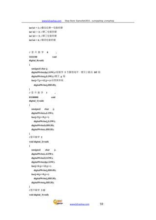
while (numChar--) {
buffer[index++] = Serial.read();
}
splitString(buffer);
}
}
void splitString(char* data)
{ Serial.print("Data entered: ");
Serial.println(data);
char* parameter;
parameter = strtok (data, " ,");
while (parameter != NULL) {
setLED(parameter);
parameter = strtok (NULL, " ,");
}
// Clear the text and serial buffers for
(int x=0; x<16; x++) {
buffer[x]='0';
}
Serial.flush();
}
void setLED(char* data) {
if ((data[0] == 'r') || (data[0] == 'R')) {
int Ans = strtol(data+1, NULL, 10);
Ans = constrain(Ans,0,255);
analogWrite(RedPin, Ans);
Serial.print("Red is set to: ");
Serial.println(Ans);
}
if ((data[0] == 'g') || (data[0] == 'G')) {
int Ans = strtol(data+1, NULL, 10);
Ans = constrain(Ans,0,255);
analogWrite(GreenPin, Ans);
Serial.print("Green is set to: ");
Serial.println(Ans);
}
if ((data[0] == 'y') || (data[0] == 'Y')) {
int Ans = strtol(data+1, NULL, 10);
= constrain(Ans,0,255);
analogWrite(YellowPin, Ans);
Serial.print("Yellow is set to: ");
Serial.println(Ans);}](https://image.slidesharecdn.com/practicasconarduino-150307145323-conversion-gate01/85/Practicas-con-arduino-37-320.jpg)
![www.b2cqshop.com Ebay Store :Eqmarket2011 , sunnyqshop ,csmqshop
www.b2cqshop.com 39
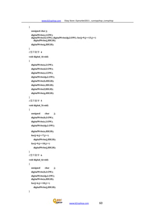
Project 3 - Code Overview
This project introduces a whole bunch of new concepts, including serial
communication, pointers and string manipulation. So, hold on to your hats this will take a
lot of explaining.
First we set up an array of char (characters) to hold our text string. We have made it
18 characters long, whichis longer than the maximum of 16 we will allow to ensure we
don’t get “buffer overflow” errors.
char buffer[18];
We then set up the integers to hold the red, green and blue values as well as the
values for the digital pins.
int red, green, blue;
int RedPin = 11; int
GreenPin = 10; int
YellowPin = 9;
In our setup function we set the 3 digital pins to be outputs. But, before that we have
the Serial.begin command.
void setup()
{ Serial.begin(9600);
Serial.flush();
pinMode(RedPin, OUTPUT);
pinMode(GreenPin, OUTPUT);
pinMode(BluePin, OUTPUT);
}
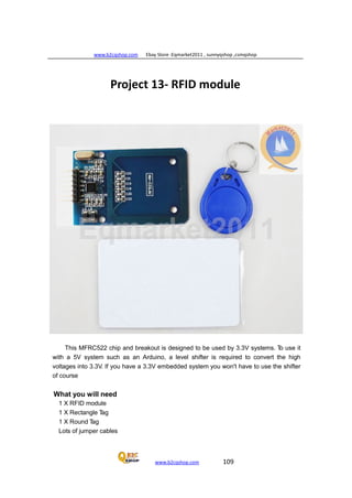
the
Serial.begin tells the Arduino to start serial communications and the number within
parenthesis, in this case 9600, sets the baud rate (characters per second) that the serial
line will communicate at.
The Serial.flush command will flush out any characters that happen to be in the
serial line so that it is empty and ready for input/output.
The serial communications line is simply a way for the Arduino to communicate with
the outside world, in this case to and from the PC and the Arduino IDE’s Serial Monitor.
In the main loop we have an if statement. The condition it is checking for is
if (Serial.available() > 0) {
The Serial.available command checks to see if any characters have been sent down
the serial line. If any characters have been received then the condition is met and the
code within the if statements code block is now executed.
if (Serial.available() > 0) {
int index=0;
delay(100); // let the buffer fill up](https://image.slidesharecdn.com/practicasconarduino-150307145323-conversion-gate01/85/Practicas-con-arduino-39-320.jpg)
![www.b2cqshop.com Ebay Store :Eqmarket2011 , sunnyqshop ,csmqshop
www.b2cqshop.com 40
int numChar = Serial.available();
if (numChar>15) {
numChar=15;
}
while (numChar--) {
buffer[index++] = Serial.read();
}
splitString(buffer);
}
An integer called index is declared and initialised as zero. This integer will hold the
position of a pointer to the characters within the char array.
We then set a delay of 100. The purpose of this is to ensure that the serial buffer (the
place in memory where the serial data that is received is stored prior to processing) is full
before we carry on and process the data. If we don’t do that, it is possible that the function
will execute and start to process the text string, before we have received all of the data.
The serial communications line is very slow compared to the speed the rest of the code is
executing at. When you send a string of characters the Serial.available function will
immediately have a value higher than zero and the if function will start to execute. If we
didn’t have the delay(100) statement in there it could start to execute the code within the if
statement before all of the text string had been received and the serial data may only be
the first few characters of the line of text entered.
After we have waited for 100ms for the serial buffer to fill up with the data sent, we then
declare and initialise the numChar integer to be the number of characters within the text
string.
E.g. If we sent this text in the Serial Monitor:
R255, G255, Y255
Then the value of numChar would be 17. It is 17 and ot 16 as at the end of each line of
text there is an invisible character called a NULL character. This is a ‘nothing’ symbol and
simply tells the Arduino that the end of the line of text has been reached.
The next if statement checks if the value of numChar is greater than 15 or not and if so it
sets it to be 15. This ensures that we don’t overflow the array char buffer[18];
After this comes a while command. This is something
we haven't come across before so let me explain. We have already used the for loop,
which will loop a set number of times. The while statement is also a loop, but one that
executes only while a condition is true.
The syntax is
while(expression) {
! // statement(s)
}
In our code the while loop is
while (numChar--) {](https://image.slidesharecdn.com/practicasconarduino-150307145323-conversion-gate01/85/Practicas-con-arduino-40-320.jpg)
![www.b2cqshop.com Ebay Store :Eqmarket2011 , sunnyqshop ,csmqshop
www.b2cqshop.com 41
buffer[index++] = Serial.read();
}
The condition it is checking is simply numChar, so in other words it is checking that the
value stored in the integer numChar is not zero. numChar has -- after it.
This is what is known as a post-decrement. In other words, the value is decremented
AFTER it is used. If we had used --numChar the value in numChar would be decremented
(have one subtracted from it) before
it was evaluated. In our case, the while loop checks the value of numChar and then
subtracts one from it.
If the value of numChar was not zero before the decrement, it then carries out the code
within its code block.
numChar is set to the length of the text string that we have entered into the Serial
Monitor window. So, the code within the while loop will execute that many times.
The code within the while loop is
buffer[index++] = Serial.read();
Which sets each element of the buffer array to each character read in from the Serial
line. In other words, t fills up the buffer array with the letters we have entered into the
Serial Monitor’s text window.
The Serial.read() command reads incoming serial data, one byte at a time.
So now that our character array has been filled with the characters we entered in the
Serial Monitor the while loop will end once numChar reaches zero (i.e. The length of the
string).
After the while loop we have
splitString(buffer);
Which is a call to one of the two functions we have created and called splitString(). The
function looks like this:
void splitString(char* data)
{ Serial.print("Data entered: ");
Serial.println(data);
char* parameter;
parameter = strtok (data, " ,");
while (parameter != NULL) {
setLED(parameter);
parameter = strtok (NULL, " ,");
}
// Clear the text and serial buffers for
(int x=0; x<16; x++) {
buffer[x]='0';
}
Serial.flush();
}
We can see that the function returns no data, hence it’s data type has been set to void.
We pass the function one parameter and that is a char data type that we have called data.](https://image.slidesharecdn.com/practicasconarduino-150307145323-conversion-gate01/85/Practicas-con-arduino-41-320.jpg)
![www.b2cqshop.com Ebay Store :Eqmarket2011 , sunnyqshop ,csmqshop
www.b2cqshop.com 44
}
is simply stripping out each part of the text string that is separated by spaces or
commas and sending that part of the string to the next function called setLED().
The final part of this function simply fills the buffer array with NULL character, which is
done with the /0 symbol and then flushes the Serial data out of the Serial buffer ready for
the next set of data to be entered.
// Clear the text and serial buffers
for (int x=0; x<16; x++) {
buffer[x]='0';
}
Serial.flush();
The setLED function is going to take each part of the text string
and set the corresponding LED to the colour we have chosen. So, if the text string we
enter is
$ G125 Y55
Then the splitString() function splits that into the two separate components
$ G125
$ Y55
and send that shortened text string onto the setLED() function, which will read it,
decide what LED we have chosen and set it to the corresponding brightness value.
So let’s take a look at the second function called setLED().
void setLED(char* data) {
if ((data[0] == 'r') || (data[0] == 'R'))
{
int Ans = strtol(data+1, NULL, 10);
Ans = constrain(Ans,0,255);
analogWrite(RedPin, Ans);
Serial.print("Red is set to: ");
Serial.println(Ans);
}
if ((data[0] == 'g') || (data[0] == 'G'))
{
int Ans = strtol(data+1, NULL, 10);
Ans = constrain(Ans,0,255);
analogWrite(GreenPin, Ans);
Serial.print("Green is set to: ");
Serial.println(Ans);
}
if ((data[0] == 'y') || (data[0] == 'Y'))
{
int Ans = strtol(data+1, NULL, 10);
Ans = constrain(Ans,0,255);](https://image.slidesharecdn.com/practicasconarduino-150307145323-conversion-gate01/85/Practicas-con-arduino-44-320.jpg)
![www.b2cqshop.com Ebay Store :Eqmarket2011 , sunnyqshop ,csmqshop
www.b2cqshop.com 45
analogWrite(YellowPin, Ans);
Serial.print("Yellow is set to: ");
Serial.println(Ans);
}
}
We can see that this function contains 3 very similar if statements. We will therefore take
a look at just one of them as the other 2 are almost identical.
if ((data[0] == 'r') || (data[0] == 'R')) {
int Ans = strtol(data+1, NULL, 10); Ans =
constrain(Ans,0,255); analogWrite(RedPin, Ans);
Serial.print("Red is set to: "); Serial.println(Ans);
}
The if statement checks that the first character in the string data[0] is either the letter r
or R (upper case and lower case characters are totally different as far as C is concerned.
We use the logical OR command whose symbol is || to check if the letter is an r OR an
R as either will do.
If it is an r or an R then the if statement knows we wish to change the brightness of
the Red LED and so the code within executes. First we declare an integer called Ans
(which has scope local to the setLED function only) and use the strtol (String to long
integer) command to convert the characters after the letter R to an integer. The strtol
command takes 3 parameters and these are the string we are passing it, a pointer to the
character after the integer (which we don’t use as we have already stripped the string
using the strtok command and hence pass a NULL character) and then the ‘base’, which
in our case is base 10 as we are using normal decimal numbers (as opposed to binary,
octal or hexadecimal which would be base 2, 8 and 16 respectively). So in other
words we declare an integer and set it to the value of the text string after the letter R (or
the number bit).
Next we use the constrain command to make sure that Ans goes from 0 to 255 and no
more. We then carry out an analogWrite command to the red pin and send it the value of
Ans. The code then sends out “Red is set to: “ followed by the value of Ans back to
the Serial Monitor. The other two if statements do exactly the same but for the Green and
the Blue LED’s.
We have covered a lot of ground and a lot of new concepts in this project. To make
sure you understand exactly what is going on in this code I am going to set the project
code side by side with pseudo-code (an fake computer language that is essentially the
computer language translated into a language humans can understand).
The C Programming Language
// Project 10 - Serial controlled RGB Lamp
char buffer[18];
int red, green, blue;
Pseudo-Code
A comment with the project number and name Declare a
character array of 18 letters Declare 3 integers called red, green](https://image.slidesharecdn.com/practicasconarduino-150307145323-conversion-gate01/85/Practicas-con-arduino-45-320.jpg)
![www.b2cqshop.com Ebay Store :Eqmarket2011 , sunnyqshop ,csmqshop
www.b2cqshop.com 46
int RedPin = 11; int
GreenPin = 10; int
YellowPin = 9; void
setup()
{ Serial.begin(9600);
Serial.flush();
pinMode(RedPin, OUTPUT);
pinMode(GreenPin, OUTPUT);
pinMode(YellowPin, OUTPUT);
}
void loop()
{
if (Serial.available() > 0) {
int index=0;
delay(100); // let the buffer fill up int
numChar = Serial.available();
if (numChar>15) {
numChar=15;
}
while (numChar--) {
buffer[index++] = Serial.read();
}
splitString(buffer);
}
}
void splitString(char* data)
{ Serial.print("Data entered: ");
Serial.println(data);
char* parameter;
parameter = strtok (data, " ,");
while (parameter != NULL)
{ setLED(parameter);
parameter = strtok (NULL, " ,");
}
// Clear the text and serial buffers for
(int x=0; x<16; x++) { buffer[x]='0';
}
Serial.flush();
}
void setLED(char* data) {
and blue An integer for which pin to use for Red LED
“ “ Green
“ “ Blue
The setup function
Set serial comms to run at 9600 chars per second
Flush the serial line
Set the red led pin to be an output pin
Same for green
And yellow
The main program loop
If data is sent down the serial line...
Declare integer called index and set to 0
Wait 100 millseconds
Set numChar to the incoming data from serial If
numchar is greater than 15 characters... Make
it 15 and no more
While numChar is not zero (subtract 1 from it) Set
element[index] to value read in (add 1) Call splitString
function and send it data in buffer
The splitstring function references buffer data
Print “Data entered: “
Print value of data and then drop down a line
Declare char data type parameter
Set it to text up to the first space or comma
While contents of parameter are not empty..
! Call the setLED function
Set parameter to next part of text string
Another comment
We will do the next line 16 times
Set each element of buffer to NULL (empty)
Flush the serial comms
A function called setLED is passed buffer](https://image.slidesharecdn.com/practicasconarduino-150307145323-conversion-gate01/85/Practicas-con-arduino-46-320.jpg)
![www.b2cqshop.com Ebay Store :Eqmarket2011 , sunnyqshop ,csmqshop
www.b2cqshop.com 47
if ((data[0] == 'r') || (data[0] == 'R'))
{
int Ans = strtol(data+1, NULL, 10);
Ans = constrain(Ans,0,255);
analogWrite(RedPin, Ans);
Serial.print("Red is set to: ");
Serial.println(Ans);
}
if ((data[0] == 'g') || (data[0] == 'G'))
{
int Ans = strtol(data+1, NULL, 10);
Ans = constrain(Ans,0,255);
analogWrite(GreenPin, Ans);
Serial.print("Green is set to: ");
Serial.println(Ans);
}
if ((data[0] == 'y') || (data[0] == 'Y'))
{
int Ans = strtol(data+1, NULL, 10); Ans
= constrain(Ans,0,255);
analogWrite(YellowPin, Ans);
Serial.print(" Yellow is set to: ");
Serial.println(Ans);
}
}
If first letter is r or R...
Set integer Ans to number in next part of text
Make sure it is between o and 255
Write that value out to the red pin
Print out “Red is set to: “ And
then the value of Ans
If first letter is g or G...
Set integer Ans to number in next part of text
Make sure it is between o and 255
Write that value out to the green pin
Print out “Green is set to: “ And
then the value of Ans
If first letter is y or Y...
Set integer Ans to number in next part of text
Make sure it is between o and 255
Write that value out to the yellow pin
Print out “Yellow is set to: “ And
then the value of Ans
Hopefully you can use this ‘pseudo-code’ to make sure you understand exactly what
is going on in this projects code.
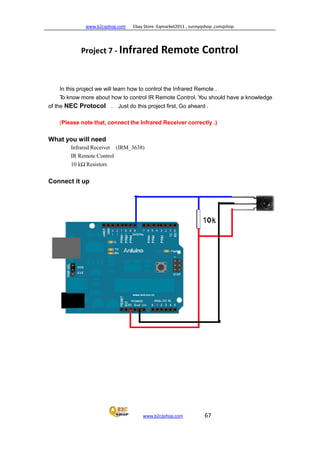
We are now going to leave LED’s behind for a little while and look at how to control a
DC Motor.](https://image.slidesharecdn.com/practicasconarduino-150307145323-conversion-gate01/85/Practicas-con-arduino-47-320.jpg)
![www.b2cqshop.com Ebay Store :Eqmarket2011 , sunnyqshop ,csmqshop
www.b2cqshop.com 49
//(courtesy of
http://www.arduino.cc/en/Tutorial/Melo
dy )
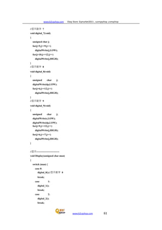
// Project 12 - Melody Player
int speakerPin = 9;
int length = 15; // the number of notes
char notes[] = "ccggaagffeeddc "; // a
space represents a rest
int beats[] = { 1, 1, 1, 1, 1, 1, 2, 1, 1,
1, 1, 1, 1, 2, 4 };
int tempo = 300;
void playTone(int tone, int duration) {
for (long i = 0; i < duration * 1000L; i +=
tone * 2) {
digitalWrite(speakerPin, HIGH);
delayMicroseconds(tone);
digitalWrite(speakerPin, LOW);
delayMicroseconds(tone);
}
}
void playNote(char note, int duration) {
char names[] = { 'c', 'd', 'e', 'f', 'g', 'a','b',
'C' };
int tones[] = { 1915, 1700, 1519, 1432,
1275,1136, 1014, 956 };
// play the tone corresponding to the
note name
for (int i = 0; i < 8; i++) { if (names[i] ==
note) { playTone(tones[i], duration);
}
}
}
void setup() {
pinMode(speakerPin, OUTPUT);
}
void loop() {
for (int i = 0; i < length; i++) { if (notes[i]
== ' ') { delay(beats[i] * tempo); // rest
} else {
playNote(notes[i], beats[i] * tempo);
}
// pause between notes delay(tempo /
2);
}
}](https://image.slidesharecdn.com/practicasconarduino-150307145323-conversion-gate01/85/Practicas-con-arduino-49-320.jpg)

![www.b2cqshop.com Ebay Store :Eqmarket2011 , sunnyqshop ,csmqshop
www.b2cqshop.com 51
Project 4 - Code Overview
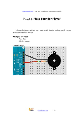
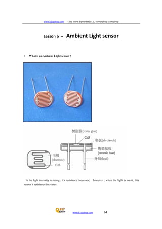
In this project we are making sounds using a piezo disc. A piezo disc can do nothing
more than make a click when we apply a voltage to it. So to get the tones we can hear out
of it we need to make it click many times a second fast enough that it becomes a
recognisable note.
The program starts off by setting up the variables we need. The piezo sounders
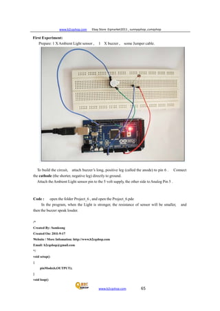
positive (red) cable is attached to Pin 9.
int speakerPin = 9;
The tune we are going to play is made up of 15 notes.
int length = 15; // the number of notes
The notes of the tune are stored in a character array as a text string.
char notes[] = "ccggaagffeeddc ";
Another array, this time of integers, is set up to store the length of each note.
int beats[] = { 1, 1, 1, 1, 1, 1, 2, 1, 1, 1, 1, 1, 1, 2, 4 };
And finally we set a tempo for the tune to be played at,
int tempo = 300;
Next you will notice that we declare two functions before our setup() and loop() functions. It
doesn’t matter if we put our own functions before or after setup() and loop(). When the program
runs, the code within these two functions will not run before setup() runs as we have not called
those functions yet.
Let’s look at the setup and loop functions before we look at the playTone and playNote
functions. All that happens in setup() is we assign the speaker pin (9) as an output.
void setup() {
pinMode(speakerPin, OUTPUT);
}
In the main program loop we have an if/else statement inside a for loop.
for (int i = 0; i < length; i++) { if
(notes[i] == ' ') { delay(beats[i] *
tempo); // rest
} else {
playNote(notes[i], beats[i] * tempo);
}
As you can see, the first if statement has as it’s condition, that the array element [i] that
the element contains a space character.
if (notes[i] == ' ')
If this is TRUE then the code within it’s block is executed.
delay(beats[i] * tempo); // rest
and this simply works out the value of eats[i] * empo nd causes a delay of that length to
cause a rest in the notes. We then have an else statement.
else {](https://image.slidesharecdn.com/practicasconarduino-150307145323-conversion-gate01/85/Practicas-con-arduino-51-320.jpg)
![www.b2cqshop.com Ebay Store :Eqmarket2011 , sunnyqshop ,csmqshop
www.b2cqshop.com 52
playNote(notes[i], beats[i] * tempo);
}
After an if statement we can extend it with an else statement. An else statements is carried
out if the condition within the if statement is false. So, for example. Let’s say we had an integer
called test and it’s value was 10 and this if/else statement:
if (test == 10) {
digitalWrite(ledPin, HIGH)
} else {
digitalWrite(ledPin, LOW)
}
Then if ‘test' had a value of 10 (which it does) the ledPin would be set to HIGH. If the
value of test was anything other than 10, the code within the else statement would be
carried out instead and the ledPin would be set to LOW.
The else statement calls a function called playNote and passes two parameters. The
first parameter is the value of notes[i] and the second is the value calculated from beats[i]
* tempo.
playNote(notes[i], beats[i] * tempo);
After if/else statement has been carried out, there is a delay
whose value is calculated by dividing tempo by 2.
delay(tempo / 2);
Let us now take a look at the two functions we have created for this project.
The first function that is called from the main program loop is playNote.
void playNote(char note, int duration) {
char names[] = { 'c', 'd', 'e', 'f', 'g', 'a',
'b', 'C' };
int tones[] = { 1915, 1700, 1519, 1432, 1275, 1136, 1014, 956 };
// play the tone corresponding to the note name for
(int i = 0; i < 8; i++) {
if (names[i] == note) {
playTone(tones[i], duration);
}
}
Two parameters have been passed to the function and within the function these have
been given the names note (character) and duration (integer).
The function sets up a local variable array of data type char called < names< . This
variable has local scope so is only visible to this function and not outside of it.
This array stores the names of the notes from middle C to high C.
We then create another array of data type integer and this array stores numbers that
correspond to the frequency of the tones, in Kilohertz, of each of the notes in the names[]
array.
int tones[] = { 1915, 1700, 1519, 1432, 1275, 1136, 1014, 956 };
After setting up the two arrays there is a for loop that looks through the 8 notes in the](https://image.slidesharecdn.com/practicasconarduino-150307145323-conversion-gate01/85/Practicas-con-arduino-52-320.jpg)
![www.b2cqshop.com Ebay Store :Eqmarket2011 , sunnyqshop ,csmqshop
www.b2cqshop.com 53
names[] array and compares it to the note sent to the function.
for (int i = 0; i < 8; i++) { if
(names[i] == note)
{ playTone(tones[i],
duration);
}
}
The tune that is sent to this function is ‘ccggaagffeeddc’ so the first note will be a middle
C.
The for loop compares that note with the notes in the names[] array and if there is a match,
calls up the second function, called play Tone, to play thecorresponding tone using in the
tones[] array using a note length of ‘duration’.
The second function is called playTone.
void playTone(int tone, int duration) {
for (long i = 0; i < duration * 1000L; i +=tone * 2)
{ digitalWrite(speakerPin, HIGH);
delayMicroseconds(tone);
digitalWrite(speakerPin, LOW);
delayMicroseconds(tone);
}
}
Two parameters are passed to this function. The first is the tone (in kilohertz) that we want the
piezo speaker to reproduce and the second is the duration (made up by calculating beats[i]
* tempo.
The function starts a for loop
for (long i = 0; i < duration * 1000L; i += tone
* 2)
As each for loop must be of a different length to make each note the same length (as
the delay differs between clicks to produce the desired frequency) the for loop will run to
< duration< multiplied by 1000 and the increment of the loop is the value of ‘tone’
multiplied by 2.
Inside the for loop we simply make the pin connected to the piezo speaker go high, wait a
short period of time, then go low, then wait another short period of time, then repeat.
digitalWrite(speakerPin, HIGH);
delayMicroseconds(tone);
digitalWrite(speakerPin, LOW);
delayMicroseconds(tone);
These repetitive clicks, of different lengths and with different pauses (of only
microseconds in length) in between clicks, makes the piezo produce a tone of varying
frequencies.](https://image.slidesharecdn.com/practicasconarduino-150307145323-conversion-gate01/85/Practicas-con-arduino-53-320.jpg)
![www.b2cqshop.com Ebay Store :Eqmarket2011 , sunnyqshop ,csmqshop
www.b2cqshop.com 76
#define data_ascii_G 0x00,0x3C,0x66,0x42,0x42,0x52,0x16,0x1E /*"G",6*/
#define data_ascii_H 0x00,0x7E,0x10,0x10,0x10,0x10,0x7E,0x00 /*"H",7*/
#define data_ascii_I 0x00,0x00,0x00,0x7E,0x00,0x00,0x00,0x00 /*"I",8*/
// display array
byte data_ascii[][display_array_size] = {
data_null,
data_ascii_A,
data_ascii_B,
data_ascii_C,
data_ascii_D,
data_ascii_E,
data_ascii_F,
data_ascii_G,
data_ascii_H,
data_ascii_I,
};
//the pin to control ROW
const int row1 = 2; // the number of the row pin 24
const int row2 = 3; // the number of the row pin 23
const int row3 = 4; // the number of the row pin 22
const int row4 = 5; // the number of the row pin 21
const int row5 = 14; // the number of the row pin 4
const int row6 = 15; // the number of the row pin 3
const int row7 = 16; // the number of the row pin 2
const int row8 = 17; // the number of the row pin 1
//the pin to control COl
const int col1 = 6; // the number of the col pin 20
const int col2 = 7; // the number of the col pin 19
const int col3 = 8; // the number of the col pin 18
const int col4 = 9; // the number of the col pin 17
const int col5 = 10; // the number of the col pin 16
const int col6 = 11; // the number of the col pin 15
const int col7 = 12; // the number of the col pin 14
const int col8 = 13; // the number of the col pin 13
void displayNum(byte rowNum,int colNum)
{
int j;
byte temp = rowNum;
for(j=2;j<6;j++)
{
digitalWrite(j, LOW);
}](https://image.slidesharecdn.com/practicasconarduino-150307145323-conversion-gate01/85/Practicas-con-arduino-76-320.jpg)
![www.b2cqshop.com Ebay Store :Eqmarket2011 , sunnyqshop ,csmqshop
www.b2cqshop.com 78
void setup(){ int i =
0 ;
for(i=2;i<14;i++)
{
pinMode(i, OUTPUT);
}
pinMode(row5, OUTPUT);
pinMode(row6, OUTPUT);
pinMode(row7, OUTPUT);
pinMode(row8, OUTPUT);
for(i=2;i<14;i++) {
digitalWrite(i, LOW);
}
digitalWrite(row5, LOW);
digitalWrite(row6, LOW);
digitalWrite(row7, LOW);
digitalWrite(row8, LOW);
}
void loop(){
int t1;
int l;
int arrage;
for(arrage=0;arrage<10;arrage++)
{
for(l=0;l<512;l++)
{
for(t1=0;t1<8;t1++)
{
displayNum(data_ascii[arrage][t1],(t1+1));
}
}
}
}](https://image.slidesharecdn.com/practicasconarduino-150307145323-conversion-gate01/85/Practicas-con-arduino-78-320.jpg)
![www.b2cqshop.com Ebay Store :Eqmarket2011 , sunnyqshop ,csmqshop
www.b2cqshop.com 97
void loop(void)
{
// call sensors.requestTemperatures() to issue a global temperature
// request to all devices on the bus
Serial.print("Requesting temperatures...");
sensors.requestTemperatures(); // Send the command to get temperatures
Serial.println("DONE");
// Loop through each device, print out temperature data
for(int i=0;i<numberOfDevices; i++)
{
// Search the wire for address
if(sensors.getAddress(tempDeviceAddress, i))
{
// Output the device ID
Serial.print("Temperature for device: ");
Serial.println(i,DEC);
// It responds almost immediately. Let's print out the data
printTemperature(tempDeviceAddress); // Use a simple function to print
out the data
}
//else ghost device! Check your power requirements and cabling
}
delay(10000);
Serial.println(":");
Serial.println(":");
Serial.println(":");
}
// function to print a device address
void printAddress(DeviceAddress deviceAddress)
{
for (uint8_t i = 0; i < 8; i++)
{
if (deviceAddress[i] < 16) Serial.print("0");
Serial.print(deviceAddress[i], HEX);
}
}](https://image.slidesharecdn.com/practicasconarduino-150307145323-conversion-gate01/85/Practicas-con-arduino-97-320.jpg)
![www.b2cqshop.com Ebay Store :Eqmarket2011 , sunnyqshop ,csmqshop
www.b2cqshop.com 113
#define Reserved12 0x1B
#define MifareReg 0x1C
#define Reserved13 0x1D
#define Reserved14 0x1E
#define SerialSpeedReg 0x1F
//Page 2:CFG
#define Reserved20 0x20
#define CRCResultRegM 0x21
#define CRCResultRegL 0x22
#define Reserved21 0x23
#define ModWidthReg 0x24
#define Reserved22 0x25
#define RFCfgReg 0x26
#define GsNReg 0x27
#define CWGsPReg 0x28
#define ModGsPReg 0x29
#define TModeReg 0x2A
#define TPrescalerReg 0x2B
#define TReloadRegH 0x2C
#define TReloadRegL 0x2D
#define TCounterValueRegH 0x2E
#define TCounterValueRegL 0x2F
//Page 3:TestRegister
#define Reserved30 0x30
#define TestSel1Reg 0x31
#define TestSel2Reg 0x32
#define TestPinEnReg 0x33
#define TestPinValueReg 0x34
#define TestBusReg 0x35
#define AutoTestReg 0x36
#define VersionReg 0x37
#define AnalogTestReg 0x38
#define TestDAC1Reg 0x39
#define TestDAC2Reg 0x3A
#define TestADCReg 0x3B
#define Reserved31 0x3C
#define Reserved32 0x3D
#define Reserved33 0x3E
#define Reserved34 0x3F
//-----------------------------------------------
//4 字节卡序列号,第 5 字节为校验字节
uchar serNum[5];](https://image.slidesharecdn.com/practicasconarduino-150307145323-conversion-gate01/85/Practicas-con-arduino-113-320.jpg)
![www.b2cqshop.com Ebay Store :Eqmarket2011 , sunnyqshop ,csmqshop
www.b2cqshop.com 114
uchar writeData[16]={0, 0, 0, 0, 0, 0, 0, 0, 0, 0, 0, 0, 0, 0, 0, 100}; //初始化 100 元钱
uchar moneyConsume = 18 ; //消费 18 元
uchar moneyAdd = 10 ; //充值 10 元
//扇区 A 密码,16 个扇区,每个扇区密码 6Byte
uchar sectorKeyA[16][16] = {{0xFF, 0xFF, 0xFF, 0xFF, 0xFF, 0xFF},
{0xFF, 0xFF, 0xFF, 0xFF, 0xFF, 0xFF},
//{0x19, 0x84, 0x07, 0x15, 0x76, 0x14},
{0xFF, 0xFF, 0xFF, 0xFF, 0xFF, 0xFF},
};
uchar sectorNewKeyA[16][16] = {{0xFF, 0xFF, 0xFF, 0xFF, 0xFF, 0xFF},
{0xFF, 0xFF, 0xFF, 0xFF, 0xFF, 0xFF,
0xff,0x07,0x80,0x69, 0x19,0x84,0x07,0x15,0x76,0x14},
//you can set another ket , such as " 0x19, 0x84, 0x07, 0x15, 0x76, 0x14 "
//{0x19, 0x84, 0x07, 0x15, 0x76, 0x14, 0xff,0x07,0x80,0x69, 0x19,0x84,0x07,0x15,0x76,0x14},
// but when loop, please set the sectorKeyA, the same key, so that RFID module can read the card
{0xFF, 0xFF, 0xFF, 0xFF, 0xFF, 0xFF,
0xff,0x07,0x80,0x69, 0x19,0x33,0x07,0x15,0x34,0x14},
};
void setup() {
Serial.begin(9600); // RFID reader SOUT pin connected to Serial RX pin at 2400bps
// start the SPI library:
SPI.begin();
// Set digital pin 10 as OUTPUT to connect it to the RFID /ENABLE pin
pinMode(chipSelectPin,OUTPUT);
digitalWrite(chipSelectPin,LOW); // Activate the RFID reader
pinMode(NRSTPD,OUTPUT); // Set digital pin 10 , Not Reset and Power-down
digitalWrite(NRSTPD, HIGH);
MFRC522_Init();
}
void loop()
{
uchar i,tmp;
uchar status;
uchar str[MAX_LEN];
uchar RC_size;
uchar blockAddr; //选择操作的块地址 0~63](https://image.slidesharecdn.com/practicasconarduino-150307145323-conversion-gate01/85/Practicas-con-arduino-114-320.jpg)
![www.b2cqshop.com Ebay Store :Eqmarket2011 , sunnyqshop ,csmqshop
www.b2cqshop.com 115
//寻卡,返回卡类型
status = MFRC522_Request(PICC_REQIDL, str);
if (status == MI_OK)
{
Serial.println("Find out a card ");
Serial.print(str[0],BIN);
Serial.print(" , ");
Serial.print(str[1],BIN);
Serial.println(" ");
}
//防冲撞,返回卡的序列号 4 字节
status = MFRC522_Anticoll(str);
memcpy(serNum, str, 5);
if (status == MI_OK)
{
Serial.println("The card's number is : ");
Serial.print(serNum[0],BIN);
Serial.print(" , ");
Serial.print(serNum[1],BIN);
Serial.print(" , ");
Serial.print(serNum[2],BIN);
Serial.print(" , ");
Serial.print(serNum[3],BIN);
Serial.print(" , ");
Serial.print(serNum[4],BIN);
Serial.println(" ");
}
//选卡,返回卡容量
RC_size = MFRC522_SelectTag(serNum);
if (RC_size != 0)
{
Serial.print("The size of the card is : ");
Serial.print(RC_size,DEC);
Serial.println(" K bits ");
}
//注册卡
blockAddr = 7; //数据块 7
status = MFRC522_Auth(PICC_AUTHENT1A, blockAddr, sectorKeyA[blockAddr/4],](https://image.slidesharecdn.com/practicasconarduino-150307145323-conversion-gate01/85/Practicas-con-arduino-115-320.jpg)
![www.b2cqshop.com Ebay Store :Eqmarket2011 , sunnyqshop ,csmqshop
www.b2cqshop.com 116
serNum); //认证
if (status == MI_OK)
{
the Sector ");
//写数据
status = MFRC522_Write(blockAddr, sectorNewKeyA[blockAddr/4]);
Serial.print("set the new card password, and can modify the data of
Serial.print(blockAddr/4,DEC);
Serial.println(" : ");
for (i=0; i<6; i++)
{
Serial.print(str[i],HEX);
Serial.print(" , ");
}
Serial.println(" ");
blockAddr = blockAddr - 3 ;
status = MFRC522_Write(blockAddr, writeData);
if(status == MI_OK)
{
$100 !");
}
Serial.println("You are B2CQSHOP VIP Member, The card has
}
//读卡
blockAddr = 7; //数据块 7
status = MFRC522_Auth(PICC_AUTHENT1A, blockAddr,
sectorNewKeyA[blockAddr/4], serNum); //认证
if (status == MI_OK)
{
//读数据
blockAddr = blockAddr - 3 ;
status = MFRC522_Read(blockAddr, str);
if (status == MI_OK)
{
Serial.println("Read from the card ,the data is : ");
for (i=0; i<16; i++)
{
Serial.print(str[i],DEC);
Serial.print(" , ");}
Serial.println(" ");
}](https://image.slidesharecdn.com/practicasconarduino-150307145323-conversion-gate01/85/Practicas-con-arduino-116-320.jpg)
![www.b2cqshop.com Ebay Store :Eqmarket2011 , sunnyqshop ,csmqshop
www.b2cqshop.com 117
}
//消费
blockAddr = 7; //数据块 7
status = MFRC522_Auth(PICC_AUTHENT1A, blockAddr,
sectorNewKeyA[blockAddr/4], serNum); //认证
if (status == MI_OK)
{
//读数据
blockAddr = blockAddr - 3 ;
status = MFRC522_Read(blockAddr, str);
if (status == MI_OK)
{
if( str[15] < moneyConsume )
{
}
else
{
Serial.println(" The money is not enough !");
str[15] = str[15] - moneyConsume;
status = MFRC522_Write(blockAddr, str);
if(status == MI_OK)
{
Serial.print("You pay $18 for items in
B2CQSHOP.COM . Now, Your money balance is : $");
Serial.print(str[15],DEC);
Serial.println(" ");
}
}
}
}
//充值
blockAddr = 7; //数据块 7
status = MFRC522_Auth(PICC_AUTHENT1A, blockAddr,
sectorNewKeyA[blockAddr/4], serNum); //认证
if (status == MI_OK)
{
//读数据
blockAddr = blockAddr - 3 ;](https://image.slidesharecdn.com/practicasconarduino-150307145323-conversion-gate01/85/Practicas-con-arduino-117-320.jpg)
![www.b2cqshop.com Ebay Store :Eqmarket2011 , sunnyqshop ,csmqshop
www.b2cqshop.com 118
status = MFRC522_Read(blockAddr, str);
if (status == MI_OK)
{
tmp = (int)(str[15] + moneyAdd) ;
//Serial.println(tmp,DEC);
if( tmp < (char)254 )
{
255 !");
}
else
{
Serial.println(" The money of the card can not be more than
str[15] = str[15] + moneyAdd ;
status = MFRC522_Write(blockAddr, str);
if(status == MI_OK)
{
Serial.print("You add $10 to your card in
B2CQSHOP.COM , Your money balance is : $");
Serial.print(str[15],DEC);
Serial.println(" ");
}
}
}
}
Serial.println(" ");
MFRC522_Halt(); //命令卡片进入休眠状态
}
/*
* 函 数 名:Write_MFRC5200
* 功能描述:向 MFRC522 的某一寄存器写一个字节数据
* 输入参数:addr--寄存器地址;val--要写入的值
* 返 回 值:无
*/
void Write_MFRC522(uchar addr, uchar val)
{
digitalWrite(chipSelectPin, LOW);
//地址格式:0XXXXXX0
SPI.transfer((addr<<1)&0x7E);
SPI.transfer(val);
digitalWrite(chipSelectPin, HIGH);
}](https://image.slidesharecdn.com/practicasconarduino-150307145323-conversion-gate01/85/Practicas-con-arduino-118-320.jpg)
![www.b2cqshop.com Ebay Store :Eqmarket2011 , sunnyqshop ,csmqshop
www.b2cqshop.com 122
void MFRC522_Reset(void)
{
Write_MFRC522(CommandReg, PCD_RESETPHASE);
}
/*
* 函 数 名:InitMFRC522
* 功能描述:初始化 RC522
* 输入参数:无
* 返 回 值:无
*/
void MFRC522_Init(void)
{
digitalWrite(NRSTPD,HIGH);
MFRC522_Reset();
//Timer: TPrescaler*TreloadVal/6.78MHz = 24ms
Write_MFRC522(TModeReg, 0x8D); //Tauto=1; f(Timer) = 6.78MHz/TPreScaler
Write_MFRC522(TPrescalerReg, 0x3E); //TModeReg[3..0] + TPrescalerReg
Write_MFRC522(TReloadRegL, 30);
Write_MFRC522(TReloadRegH, 0);
Write_MFRC522(TxAutoReg, 0x40); //100%ASK
Write_MFRC522(ModeReg, 0x3D); //CRC 初 始 值
0x6363 ???
//ClearBitMask(Status2Reg, 0x08); //MFCrypto1On=0
//Write_MFRC522(RxSelReg, 0x86); //RxWait = RxSelReg[5..0]
//Write_MFRC522(RFCfgReg, 0x7F); //RxGain = 48dB
AntennaOn(); //打开天线
}
/*
* 函 数 名:MFRC522_Request
* 功能描述:寻卡,读取卡类型号
* 输入参数:reqMode--寻卡方式,
* TagType--返回卡片类型
* 0x4400 = Mifare_UltraLight](https://image.slidesharecdn.com/practicasconarduino-150307145323-conversion-gate01/85/Practicas-con-arduino-121-320.jpg)
![www.b2cqshop.com Ebay Store :Eqmarket2011 , sunnyqshop ,csmqshop
www.b2cqshop.com 123
* 0x0400 = Mifare_One(S50)
* 0x0200 = Mifare_One(S70)
* 0x0800 = Mifare_Pro(X)
* 0x4403 = Mifare_DESFire
* 返 回 值:成功返回 MI_OK
*/
uchar MFRC522_Request(uchar reqMode, uchar *TagType)
{
uchar status;
uint backBits; //接收到的数据位数
Write_MFRC522(BitFramingReg,0x07); //TxLastBists = BitFramingReg[2..0] ???
TagType[0] = reqMode;
status = MFRC522_ToCard(PCD_TRANSCEIVE, TagType, 1, TagType, &backBits);
if ((status != MI_OK) || (backBits != 0x10))
{
status = MI_ERR;
}
return status;
}
/*
* 函 数 名:MFRC522_ToCard
* 功能描述:RC522 和 ISO14443 卡通讯
* 输入参数:command--MF522 命令字,
* sendData--通过 RC522 发送到卡片的数据,
* sendLen--发送的数据长度
* backData--接收到的卡片返回数据,
* backLen--返回数据的位长度
* 返 回 值:成功返回 MI_OK
*/
uchar MFRC522_ToCard(uchar command, uchar *sendData, uchar sendLen, uchar *backData, uint
*backLen)
{
uchar status = MI_ERR;
uchar irqEn = 0x00;
uchar waitIRq = 0x00;
uchar lastBits;
uchar n;
uint i;](https://image.slidesharecdn.com/practicasconarduino-150307145323-conversion-gate01/85/Practicas-con-arduino-122-320.jpg)
![www.b2cqshop.com Ebay Store :Eqmarket2011 , sunnyqshop ,csmqshop
www.b2cqshop.com 124
switch (command)
{
case PCD_AUTHENT: //认证卡密
{
irqEn = 0x12;
waitIRq = 0x10;
break;
}
case PCD_TRANSCEIVE: //发送 FIFO 中数据
{
irqEn = 0x77;
waitIRq = 0x30;
break;
}
default:
break;
}
Write_MFRC522(CommIEnReg, irqEn|0x80); //允许中断请求
ClearBitMask(CommIrqReg, 0x80); //清除所有中断请求位
SetBitMask(FIFOLevelReg, 0x80); //FlushBuffer=1, FIFO 初始化
Write_MFRC522(CommandReg, PCD_IDLE); //NO action;取消当前命令 ???
//向 FIFO 中写入数据
for (i=0; i<sendLen; i++)
{
Write_MFRC522(FIFODataReg, sendData[i]);
}
//执行命令
Write_MFRC522(CommandReg, command);
if (command == PCD_TRANSCEIVE)
{
SetBitMask(BitFramingReg, 0x80); //StartSend=1,transmission of data starts
}
//等待接收数据完成
i = 2000; //i 根据时钟频率调整,操作 M1 卡最大等待时间 25ms ???
do
{
//CommIrqReg[7..0]
//Set1 TxIRq RxIRq IdleIRq HiAlerIRq LoAlertIRq ErrIRq TimerIRq](https://image.slidesharecdn.com/practicasconarduino-150307145323-conversion-gate01/85/Practicas-con-arduino-123-320.jpg)
![www.b2cqshop.com Ebay Store :Eqmarket2011 , sunnyqshop ,csmqshop
www.b2cqshop.com 125
n = Read_MFRC522(CommIrqReg);
i--;
}
while ((i!=0) && !(n&0x01) && !(n&waitIRq));
ClearBitMask(BitFramingReg, 0x80); //StartSend=0
if (i != 0)
{
if(!(Read_MFRC522(ErrorReg) & 0x1B)) //BufferOvfl Collerr CRCErr ProtecolErr
{
status = MI_OK;
if (n & irqEn & 0x01)
{
status = MI_NOTAGERR; //??
}
if (command == PCD_TRANSCEIVE)
{
n = Read_MFRC522(FIFOLevelReg);
lastBits = Read_MFRC522(ControlReg) & 0x07;
if (lastBits)
{
}
else
{
}
*backLen = (n-1)*8 + lastBits;
*backLen = n*8;
if (n == 0)
{
n = 1;
}
if (n > MAX_LEN)
{
n = MAX_LEN;
}
//读取 FIFO 中接收到的数据
for (i=0; i<n; i++)
{
backData[i] = Read_MFRC522(FIFODataReg);](https://image.slidesharecdn.com/practicasconarduino-150307145323-conversion-gate01/85/Practicas-con-arduino-124-320.jpg)
![www.b2cqshop.com Ebay Store :Eqmarket2011 , sunnyqshop ,csmqshop
www.b2cqshop.com 126
}
}
}
else
{
status = MI_ERR;
}
}
//SetBitMask(ControlReg,0x80); //timer stops
//Write_MFRC522(CommandReg, PCD_IDLE);
return status;
}
/*
* 函 数 名:MFRC522_Anticoll
* 功能描述:防冲突检测,读取选中卡片的卡序列号
* 输入参数:serNum--返回 4 字节卡序列号,第 5 字节为校验字节
* 返 回 值:成功返回 MI_OK
*/
uchar MFRC522_Anticoll(uchar *serNum)
{
uchar status;
uchar i;
uchar serNumCheck=0;
uint unLen;
//ClearBitMask(Status2Reg, 0x08); //TempSensclear
//ClearBitMask(CollReg,0x80); //ValuesAfterColl
Write_MFRC522(BitFramingReg,0x00); //TxLastBists = BitFramingReg[2..0]
serNum[0] = PICC_ANTICOLL;
serNum[1] = 0x20;
status = MFRC522_ToCard(PCD_TRANSCEIVE, serNum, 2, serNum, &unLen);
if (status == MI_OK)
{
//校验卡序列号
for (i=0; i<4; i++)](https://image.slidesharecdn.com/practicasconarduino-150307145323-conversion-gate01/85/Practicas-con-arduino-125-320.jpg)
![www.b2cqshop.com Ebay Store :Eqmarket2011 , sunnyqshop ,csmqshop
www.b2cqshop.com 127
{
serNumCheck ^= serNum[i];
}
if (serNumCheck != serNum[i])
{
status = MI_ERR;
}
}
//SetBitMask(CollReg, 0x80); //ValuesAfterColl=1
return status;
}
/*
* 函 数 名:CalulateCRC
* 功能描述:用 MF522 计算 CRC
* 输入参数:pIndata--要读数 CRC 的数据,len--数据长度,pOutData--计算的 CRC 结果
* 返 回 值:无
*/
void CalulateCRC(uchar *pIndata, uchar len, uchar *pOutData)
{
uchar i, n;
ClearBitMask(DivIrqReg, 0x04); //CRCIrq = 0
SetBitMask(FIFOLevelReg, 0x80); //清 FIFO 指针
//Write_MFRC522(CommandReg, PCD_IDLE);
//向 FIFO 中写入数据
for (i=0; i<len; i++)
{
Write_MFRC522(FIFODataReg, *(pIndata+i));
}
Write_MFRC522(CommandReg, PCD_CALCCRC);
//等待 CRC 计算完成
i = 0xFF;
do
{
n = Read_MFRC522(DivIrqReg);
i--;
}](https://image.slidesharecdn.com/practicasconarduino-150307145323-conversion-gate01/85/Practicas-con-arduino-126-320.jpg)
![www.b2cqshop.com Ebay Store :Eqmarket2011 , sunnyqshop ,csmqshop
www.b2cqshop.com 128
while ((i!=0) && !(n&0x04)); //CRCIrq = 1
//读取 CRC 计算结果
pOutData[0] = Read_MFRC522(CRCResultRegL);
pOutData[1] = Read_MFRC522(CRCResultRegM);
}
/*
* 函 数 名:MFRC522_SelectTag
* 功能描述:选卡,读取卡存储器容量
* 输入参数:serNum--传入卡序列号
* 返 回 值:成功返回卡容量
*/
uchar MFRC522_SelectTag(uchar *serNum)
{
uchar i; uchar
status; uchar
size; uint
recvBits;
uchar buffer[9];
//ClearBitMask(Status2Reg, 0x08); //MFCrypto1On=0
buffer[0] = PICC_SElECTTAG;
buffer[1] = 0x70;
for (i=0; i<5; i++)
{
buffer[i+2] = *(serNum+i);
}
CalulateCRC(buffer, 7, &buffer[7]); //??
status = MFRC522_ToCard(PCD_TRANSCEIVE, buffer, 9, buffer, &recvBits);
if ((status == MI_OK) && (recvBits == 0x18))
{
}
else
{
}
size = buffer[0];
size = 0;
return size;](https://image.slidesharecdn.com/practicasconarduino-150307145323-conversion-gate01/85/Practicas-con-arduino-127-320.jpg)
![www.b2cqshop.com Ebay Store :Eqmarket2011 , sunnyqshop ,csmqshop
www.b2cqshop.com 129
}
/*
* 函 数 名:MFRC522_Auth
* 功能描述:验证卡片密码
* 输入参数:authMode--密码验证模式
0x60 = 验证 A 密
钥
0x61 = 验证 B 密
钥 BlockAddr-- 块 地 址
Sectorkey--扇区密码
serNum--卡片序列号,4 字节
* 返 回 值:成功返回 MI_OK
*/
uchar MFRC522_Auth(uchar authMode, uchar BlockAddr, uchar *Sectorkey, uchar *serNum)
{
uchar status;
uint recvBits;
uchar i;
uchar buff[12];
//验证指令+块地址+扇区密码+卡序列号
buff[0] = authMode;
buff[1] = BlockAddr;
for (i=0; i<6; i++)
{
buff[i+2] = *(Sectorkey+i);
}
for (i=0; i<4; i++)
{
buff[i+8] = *(serNum+i);
}
status = MFRC522_ToCard(PCD_AUTHENT, buff, 12, buff, &recvBits);
if ((status != MI_OK) || (!(Read_MFRC522(Status2Reg) & 0x08)))
{
status = MI_ERR;
}
return status;
}](https://image.slidesharecdn.com/practicasconarduino-150307145323-conversion-gate01/85/Practicas-con-arduino-128-320.jpg)
![www.b2cqshop.com Ebay Store :Eqmarket2011 , sunnyqshop ,csmqshop
www.b2cqshop.com 130
/*
* 函 数 名:MFRC522_Read
* 功能描述:读块数据
* 输入参数:blockAddr--块地址;recvData--读出的块数据
* 返 回 值:成功返回 MI_OK
*/
uchar MFRC522_Read(uchar blockAddr, uchar *recvData)
{
uchar status;
uint unLen;
recvData[0] = PICC_READ; recvData[1]
= blockAddr; CalulateCRC(recvData,2,
&recvData[2]);
status = MFRC522_ToCard(PCD_TRANSCEIVE, recvData, 4, recvData, &unLen);
if ((status != MI_OK) || (unLen != 0x90))
{
status = MI_ERR;
}
return status;
}
/*
* 函 数 名:MFRC522_Write
* 功能描述:写块数据
* 输入参数:blockAddr--块地址;writeData--向块写 16 字节数据
* 返 回 值:成功返回 MI_OK
*/
uchar MFRC522_Write(uchar blockAddr, uchar *writeData)
{
uchar status;
uint recvBits;
uchar i;
uchar buff[18];
buff[0] = PICC_WRITE; buff[1]
= blockAddr; CalulateCRC(buff,
2, &buff[2]);
status = MFRC522_ToCard(PCD_TRANSCEIVE, buff, 4, buff, &recvBits);](https://image.slidesharecdn.com/practicasconarduino-150307145323-conversion-gate01/85/Practicas-con-arduino-129-320.jpg)
![www.b2cqshop.com Ebay Store :Eqmarket2011 , sunnyqshop ,csmqshop
www.b2cqshop.com 131
if ((status != MI_OK) || (recvBits != 4) || ((buff[0] & 0x0F) != 0x0A))
{
status = MI_ERR;
}
if (status == MI_OK)
{
for (i=0; i<16; i++) //向 FIFO 写 16Byte 数据
{
buff[i] = *(writeData+i);
}
CalulateCRC(buff, 16, &buff[16]);
status = MFRC522_ToCard(PCD_TRANSCEIVE, buff, 18, buff, &recvBits);
if ((status != MI_OK) || (recvBits != 4) || ((buff[0] & 0x0F) != 0x0A))
{
status = MI_ERR;
}
}
return status;
}
/*
* 函 数 名:MFRC522_Halt
* 功能描述:命令卡片进入休眠状态
* 输入参数:无
* 返 回 值:无
*/
void MFRC522_Halt(void)
{
uchar status;
uint unLen;
uchar buff[4];
buff[0] = PICC_HALT;
buff[1] = 0;
CalulateCRC(buff, 2, &buff[2]);
status = MFRC522_ToCard(PCD_TRANSCEIVE, buff, 4, buff,&unLen);
}](https://image.slidesharecdn.com/practicasconarduino-150307145323-conversion-gate01/85/Practicas-con-arduino-130-320.jpg)

![www.b2cqshop.com Ebay Store :Eqmarket2011 , sunnyqshop ,csmqshop
www.b2cqshop.com 136
0X00 0X00 0X00 0X00 0X00 0X00
0XAB 0XCD 0XEF 0X12 0X34 0X56
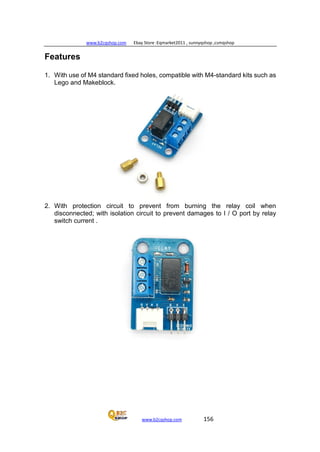
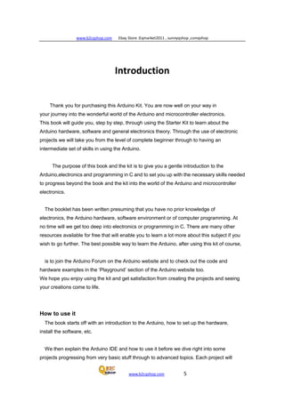
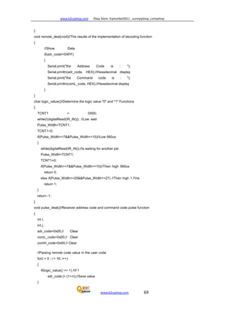
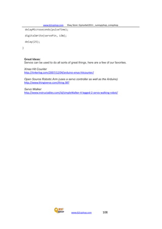
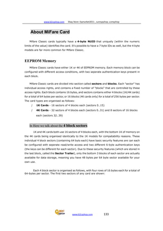
Example of a New Mifare Classic 1K Card
The follow memory dump illustrates the structure of a 1K Mifare Classic Card,
where the data and Sector Trailer blocks can be clearly seen:
[-------------------------Start of Memory Dump-----------------------]
------------------------Sector 0--------------------
Block 0 8E 02 6F 66 85 08 04 00 62 63 64 65 66 67 68 69 ?.of?...bcdefghi
Block 1 00 00 00 00 00 00 00 00 00 00 00 00 00 00 00 00 ................
Block 2 00 00 00 00 00 00 00 00 00 00 00 00 00 00 00 00 ................
Block 3 00 00 00 00 00 00 FF 07 80 69 FF FF FF FF FF FF ......ÿ.?iÿÿÿÿÿÿ
------------------------Sector 1-------------------------
Block 4 00 00 00 00 00 00 00 00 00 00 00 00 00 00 00 00 ................
Block 5 00 00 00 00 00 00 00 00 00 00 00 00 00 00 00 00 ................
Block 6 00 00 00 00 00 00 00 00 00 00 00 00 00 00 00 00 ................
Block 7 00 00 00 00 00 00 FF 07 80 69 FF FF FF FF FF FF ......ÿ.?iÿÿÿÿÿÿ
------------------------Sector 2-------------------------
Block 8 00 00 00 00 00 00 00 00 00 00 00 00 00 00 00 00 ................
Block 9 00 00 00 00 00 00 00 00 00 00 00 00 00 00 00 00 ................
Block 10 00 00 00 00 00 00 00 00 00 00 00 00 00 00 00 00 ................
Block 11 00 00 00 00 00 00 FF 07 80 69 FF FF FF FF FF FF ......ÿ.?iÿÿÿÿÿÿ
------------------------Sector 3-------------------------](https://image.slidesharecdn.com/practicasconarduino-150307145323-conversion-gate01/85/Practicas-con-arduino-135-320.jpg)
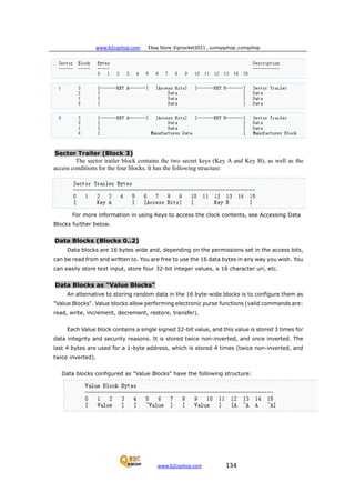
![www.b2cqshop.com Ebay Store :Eqmarket2011 , sunnyqshop ,csmqshop
www.b2cqshop.com 139
Block 51 00 00 00 00 00 00 FF 07 80 69 FF FF FF FF FF FF ......ÿ.?iÿÿÿÿÿÿ
------------------------Sector 13-------------------------
Block 52 00 00 00 00 00 00 00 00 00 00 00 00 00 00 00 00 ................ Block
53 00 00 00 00 00 00 00 00 00 00 00 00 00 00 00 00 ................ Block 54
00 00 00 00 00 00 00 00 00 00 00 00 00 00 00 00 ................ Block 55 00
00 00 00 00 00 FF 07 80 69 FF FF FF FF FF FF ......ÿ.?iÿÿÿÿÿÿ
------------------------Sector 14-------------------------
Block 56 00 00 00 00 00 00 00 00 00 00 00 00 00 00 00 00 ................ Block
57 00 00 00 00 00 00 00 00 00 00 00 00 00 00 00 00 ................ Block 58
00 00 00 00 00 00 00 00 00 00 00 00 00 00 00 00 ................ Block 59 00
00 00 00 00 00 FF 07 80 69 FF FF FF FF FF FF ......ÿ.?iÿÿÿÿÿÿ
------------------------Sector 15-------------------------
Block 60 00 00 00 00 00 00 00 00 00 00 00 00 00 00 00 00 ................ Block
61 00 00 00 00 00 00 00 00 00 00 00 00 00 00 00 00 ................ Block 62
00 00 00 00 00 00 00 00 00 00 00 00 00 00 00 00 ................ Block 63 00
00 00 00 00 00 FF 07 80 69 FF FF FF FF FF FF ......ÿ.?iÿÿÿÿÿÿ
[------------------------End of Memory Dump--------------------------]](https://image.slidesharecdn.com/practicasconarduino-150307145323-conversion-gate01/85/Practicas-con-arduino-138-320.jpg)