1. Call and Message using Arduino and GSM Module
By Saddam 15 Comments
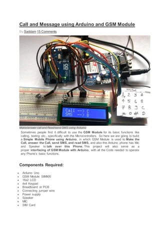
Make/answer call and Read/send SMS using Arduino
Sometimes people find it difficult to use the GSM Module for its basic functions like
calling, texting etc., specifically with the Microcontrollers. So here we are going to build
a Simple Mobile Phone using Arduino, in which GSM Module is used to Make the
Call, answer the Call, send SMS, and read SMS, and also this Arduino phone has Mic
and Speaker to talk over this Phone. This project will also serve as a
proper interfacing of GSM Module with Arduino, with all the Code needed to operate
any Phone’s basic functions.
Components Required:
Arduino Uno
GSM Module SIM900
16x2 LCD
4x4 Keypad
Breadboard or PCB
Connecting jumper wire
Power supply
Speaker
MIC
SIM Card
2. Working Explanation:
In this Arduino Mobile Phone Project, we have used Arduino Uno to control whole
system’s features and interfacing all the components in this system. A 4x4
Alphanumeric Keypad is used for taking all kind of inputs like: Enter mobile number,
type messages, make a call, receive a call, send SMS, read SMS etc. GSM Module is
used to communicate with the network for calling and messaging purpose. We have
also interfaced a MIC and a Speaker for Voice Call and Ring sound and a 16x2 LCD is
used for showing messages, instructions and alerts.
Alphanumeric is a method to enter numbers and alphabets both by using same
keypad. In this method, we have interfaced 4x4 keypad with Arduino and written Code
for accepting alphabets too, check the Code in Code section below.
Working of this project is easy. All the features will be performed by Using Alphanumeric
Keypad. Check the Full code and a Demo Video below to properly understand the
process. Here we are going to explain all the four features of the projects below.
Explaining Four Features of Arduino Mobile Phone:
1. Make a Call:
To make a call by using our Arduino based Phone, we have to press ‘C’ and then need
to enter the Mobile Number on which we want to make a call. Number will be entered
by using alphanumeric keypad. After entering the number we again need to press ‘C’.
Now Arduino will process for connecting the call to the entered number by using AT
command:
ATDxxxxxxxxxx; <Enter> where xxxxxxxxx is entered Mobile Number.
2. Receive a Call:
Receiving a call is very easy. When someone is calling to your system SIM number,
which is there in GSM Module, then your system will show ‘Incoming…’ message over
the LCD with incoming number of caller. Now we just need to Press ‘A’ to attend this
call. When we press ‘A’, Arduino will send given command to GSM Module:
3. ATA <enter>
3. Send SMS:
When we want to send a SMS using our Arduino based Mobile Phone, then we need to
Press ‘B’. Now System will ask for Recipient Number, means ‘to whom’ we want to send
SMS. After entering the number we need to press ‘D’ and now LCD asks for message.
Now we need to type the message, like we enter in normal mobile, by using keypad and
then after entering the message we need to press ‘D’ to send SMS. To Send SMS
Arduino sends given command:
AT+CMGF=1 <enter>
AT+CMGS=”xxxxxxxxxx” <enter> where: xxxxxxxxxx is entered mobile number
And send 26 to GSM to send SMS.
4. Receive and Read SMS:
This feature is also simple. In this, GSM will receive SMS and stores it in SIM card. And
Arduino continuously monitors the received SMS indication over UART. We just need
to Press ‘D’, to read the SMS, when we see the New Message symbol (like a envelope:
See the Video at the end) on the LCD. Below is the SMS Received indication
displayed on the Serial port is:
+CMTI: “SM” <SMS stored location>
+CMTI: “SM”,6 Where 6 is message location where it stored in SIM card.
When Arduino gets this ‘SMS received’ indication then it extracts SMS storing location
and sends command to GSM to read the received SMS. And show a ‘New Message
Symbol’ over the LCD.
AT+CMGR=<SMS stored location><enter>
AT+CMGR=6
Now GSM sends stored message to Arduino and then Arduino extract main SMS and
display it over the LCD and then after reading this SMS Arduino Clear the ‘New SMS
symbol’ from the LCD.
Note: There is no coding for MIC and Speaker.
Check the Full code and a Demo Video below to properly understand the process.
Circuit Diagram and Explanation:
4. Circuit Diagram of this for interfacing GSM SIM900 and Arduino is given above. 16x2
LCD pins RS, EN, D4, D5, D6 and D7 are connected with pin number 14, 15, 16, 17, 18
and 19 of Arduino respectively. GSM Module’s Rx and Tx pins are directly connected
with Arduino’s pin D3 and D2 respectively (Ground of Arduino and GSM must be
connected with each other). 4x4 keypad Row pins R1, R2, R3, R4 are directly linked to
pin number 11,10, 9, 8 of Arduino and Colum pins of keypad C1, C2, C3 are linked with
pin number 7, 6, 5, 4 of Arduino. MIC is directly connected at mic+ and mic- of GSM
Module and Speaker is directly connected at SP+ and SP- pins for GSM Module.
Programming Explanation:
Programming part of this project is little complex for beginners. In this code we have
used keypad library #include <Keypad.h> for interfacing simple keypad for entering
numbers. And for entering alphabets with the same keypad, we have created
function void alfakey(). Means we have made every key multi functioning and we can
enter any character or integer by using only 10 keys.
5. Like if we press key 2 (abc2), it will show ‘a’ and if we presses it again then it will replace
‘a’ to ‘b’ and if again we press three times then it will show ‘c’ at same place in LCD. If
we wait for some time after pressing key, cursor will automatic move to next position in
LCD. Now we can enter next char or number. The same procedure is applied for other
keys.
#include <Keypad.h>
const byte ROWS = 4; //four rows
const byte COLS = 4; //four columns
char hexaKeys[ROWS][COLS] =
{
{'1','2','3','A'},
{'4','5','6','B'},
{'7','8','9','C'},
{'*','0','#','D'}
};
byte rowPins[ROWS] = {11, 10, 9, 8}; //connect to the row pinouts of the keypad
byte colPins[COLS] = {7, 6, 5, 4}; //connect to the column pinouts of the keypad
//initialize an instance of class NewKeypad
Keypad customKeypad = Keypad( makeKeymap(hexaKeys), rowPins, colPins, ROWS, COLS);
void alfakey()
{
int x=0,y=0;
int num=0;
while(1)
{
lcd.cursor();
char key=customKeypad.getKey();
if(key)
{
if(key=='1')
{
num=0;
lcd.setCursor(x,y);
6. .... .....
........ ....
Apart from operating keypad, we have created many other functions like void call() for
calling feature of Phone, void sms() for messaging feature, void lcd_status() for display
LCD status void gsm_init()for initializing the GSM Module etc. Check below all other
function related to make & receive Call and send & read SMS using GSM Module
and Arduino. All the functions are self-explanatory and understandable.
Code:
#include <SoftwareSerial.h>
SoftwareSerial Serial1(2, 3); // RX, TX
#include<LiquidCrystal.h>
LiquidCrystal lcd(14,15,16,17,18,19);
byte back[8] =
{
0b00000,
0b00000,
0b11111,
0b10101,
0b11011,
0b11111,
0b00000,
0b00000
};
String number="";
String msg="";
String instr="";
String str_sms="";
String str1="";
int ring=0;
int i=0,temp=0;
int sms_flag=0;
char sms_num[3];
int rec_read=0;
int temp1=0;
#include <Keypad.h>
const byte ROWS = 4; //four rows
const byte COLS = 4; //four columns
char hexaKeys[ROWS][COLS] =
{
{'1','2','3','A'},
{'4','5','6','B'},
{'7','8','9','C'},
{'*','0','#','D'}
};
byte rowPins[ROWS] = {11, 10, 9, 8}; //connect to the row pinouts of the keypad
byte colPins[COLS] = {7, 6, 5, 4}; //connect to the column pinouts of the keypad
//initialize an instance of class NewKeypad
Keypad customKeypad = Keypad( makeKeymap(hexaKeys), rowPins, colPins, ROWS, COLS);
String ch="1,.?!@abc2def3ghi4jkl5mno6pqrs7tuv8wxyz90 ";
18. lcd.print("Finding Network..");
boolean net_flag=1;
while(net_flag)
{
Serial1.println("AT+CPIN?");
while(Serial1.available()>0)
{
if(Serial1.find("+CPIN: READY"))
net_flag=0;
}
delay(1000);
}
lcd.clear();
lcd.print("Network Found..");
delay(1000);
lcd.clear();
}
void serialEvent()
{
while(Serial1.available())
{
char ch=Serial1.read();
instr+=ch;
i++;
if(instr[i-4] == 'R' && instr[i-3] == 'I' && instr[i-2] == 'N' && instr[i-1] == 'G' )
{
ring=1;
}
if(instr.indexOf("NO CARRIER")>=0)
{
ring=0;
i=0;
}
if(instr.indexOf("+CMTI: "SM"")>=0)
{
sms_flag=1;
}
}
}
Video:
JLCPCB - Prototype PCBs for $2 + Free Shipping on First
Order
China's Largest PCB Prototype Manufacturer, 290,000+ Customers & 8,000+ Online
Orders Per Day
10 PCBs Price: $2 for 2-layer, $15 for 4-layer, $74 for 6-layer
Add new comment
Comments (15)
19. teja
o reply
Arduino: 1.6.4 (Windows 8.1), Board: "Arduino Duemilanove or Diecimila, ATmega328"
mobilefull2.ino: In function 'void setup()':
mobilefull2:51: error: 'gsm_init' was not declared in this scope
mobilefull2.ino: In function 'void loop()':
mobilefull2:58: error: 'serialEvent' was not declared in this scope
mobilefull2:135: error: 'sms' was not declared in this scope
mobilefull2.ino: In function 'void call()':
mobilefull2:183: error: 'serialEvent' was not declared in this scope
'gsm_init' was not declared in this scope
This report would have more information with
"Show verbose output during compilation"
enabled in File > Preferences.
Sep 05, 2016
gunjan vyas
o reply
20. after initializing the display shows only one message "finding module" and there is no further
process being done by the circuit. please give proper solution.
Oct 06, 2016
harish kumar
o reply
when i compiling the code it show,
error compiling for arduino uno board
what i do sir
Nov 10, 2016
harish kumar
o reply
what type of speaker u used sir ?
Nov 12, 2016
Mark
o reply
Looks good.
Feb 07, 2017
21. Karlos
o reply
after initializing the display shows only one message "finding module.." and there is no further
process being done by the circuit. please give proper solution.
what's next? please
Feb 18, 2017
sachit kumaar
o reply
Tell me the command code for displaying messages through LCD via gsm900A...pls rply sir as
soon as possible
Feb 27, 2017
Sonadarshan
o reply
Actually I made this project all worked properly after wards means after working for a day It
stopped working in the sense the LCD is giving garbage value after call -c n message display
Apr 04, 2017
22. mufaddal
o reply
dear i need your help as admin is not replying i made this project but unfortunatly it leaves me
with finding module kindly help
Apr 28, 2017
ABDUL
o reply
when i compile it it shows error compiling
Apr 19, 2017
john
o reply
Hi sir when i compiling the code it show,
error compiling for arduino uno board
what i do sir
Jul 26, 2017
23. shahid
o reply
all the functions are working except the sms , i am not recieving the sms frm my mobile to lcd,
void serialEvent()
{
while(Serial1.available())
{
char ch=Serial1.read();
instr+=ch;
i++;
if(instr[i-4] == 'R' && instr[i-3] == 'I' && instr[i-2] == 'N' && instr[i-1] == 'G' )
{
ring=1;
}
if(instr.indexOf("NO CARRIER")>=0)
{
ring=0;
i=0;
}
if(instr.indexOf("+CMTI: "SM"")>=0)
{
sms_flag=1;
}
}
}
my serial monitor is not recieving this indication from serial,
please help as soon as possible
Dec 21, 2017
Prom
o reply
24. My code is showing errors:
'gsm_init() was not declared in this scope'
I need help
Jan 13, 2018
k
o reply
hey guys please help me ... My project GSM based intilay GMS modem send me msg but when i
send comond to refil my LIquid tank it will not work..
Jan 15, 2018
Kanwar
o reply
When Gsm send me msg then i send a msg to again gsm it will not accept my msg request
String inputString="";
String num;
int trigPin=52;
int echoPin=53;
long duration,distance;
int motor=8;
int a;
int maxiumRange=50;
String destinationNumber="+923312775616";
void setup() { // void Setup Start
Serial.begin(9600);
pinMode(motor,OUTPUT);
25. pinMode(trigPin,OUTPUT);
pinMode(echoPin,INPUT);
LCD.begin(16,2);
LCD.setCursor(0,0);
LCD.print("WELCOME");
gsm.begin(9600);
gsm.println("AT+CMGF=1"); //FOR TEXT MODE
gsm.println("AT+CNMI=2,2,0,0,0"); //DIRECT MODE NO NEED TO SAVE INCOMING
MESSAGES
delay(2000);
Serial.print("Hello Iam Conneted With Arduino"); //GSM conneted to arduino
delay(2000);
LCD.clear();
LCD.setCursor(0,0);
LCD.print("Liquid Level:");
} //void Setup Close
void loop() { //LOOP start 1
digitalWrite(trigPin,LOW);
delayMicroseconds (2000);
digitalWrite(trigPin,HIGH);
delayMicroseconds (15);
digitalWrite(trigPin,LOW);
delayMicroseconds(10);
duration= pulseIn(echoPin,HIGH);
distance= duration*0.034/2;
LCD.setCursor(0,1);
LCD.print(" ");
LCD.setCursor(0,1);
LCD.print(distance);
LCD.println("=CM");
delay(500);
if (distance >=10){ // if condtion start 1
gsm.print("AT+CMGF=1r"); // AT command to send SMS message to subsriber
delay(1000);
gsm.println("AT+CMGS= ""+destinationNumber+"""); //Serial.println("AT + CMGS =
"+923041806419""); // recipient's mobile number, in international format
delay(1000);
gsm.println("your Tank is Empty Do you Want To refill "); // message to send
26. delay(1000);
gsm.println((char)26); // End AT command with a ^Z, ASCII code 26
delay(1000);
gsm.println();
delay(10000);
if(gsm.available()){ //Coming MSG from DestionNumber Owner if2
char inChar = gsm.read();
if (inChar =='+') { // if3
num=gsm.readStringUntil(':');
if(num=="CMT"){ //if4
gsm.readStringUntil(',');
gsm.readStringUntil('"');
gsm.readStringUntil('#');
inputString=gsm.readStringUntil('$');
Serial.println(inputString);
if(inputString=="motoron"){ // Motor On code if5
digitalWrite(motor,HIGH);
delay(100);
}
Jan 15, 2018