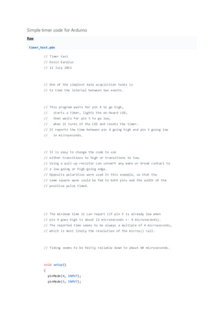
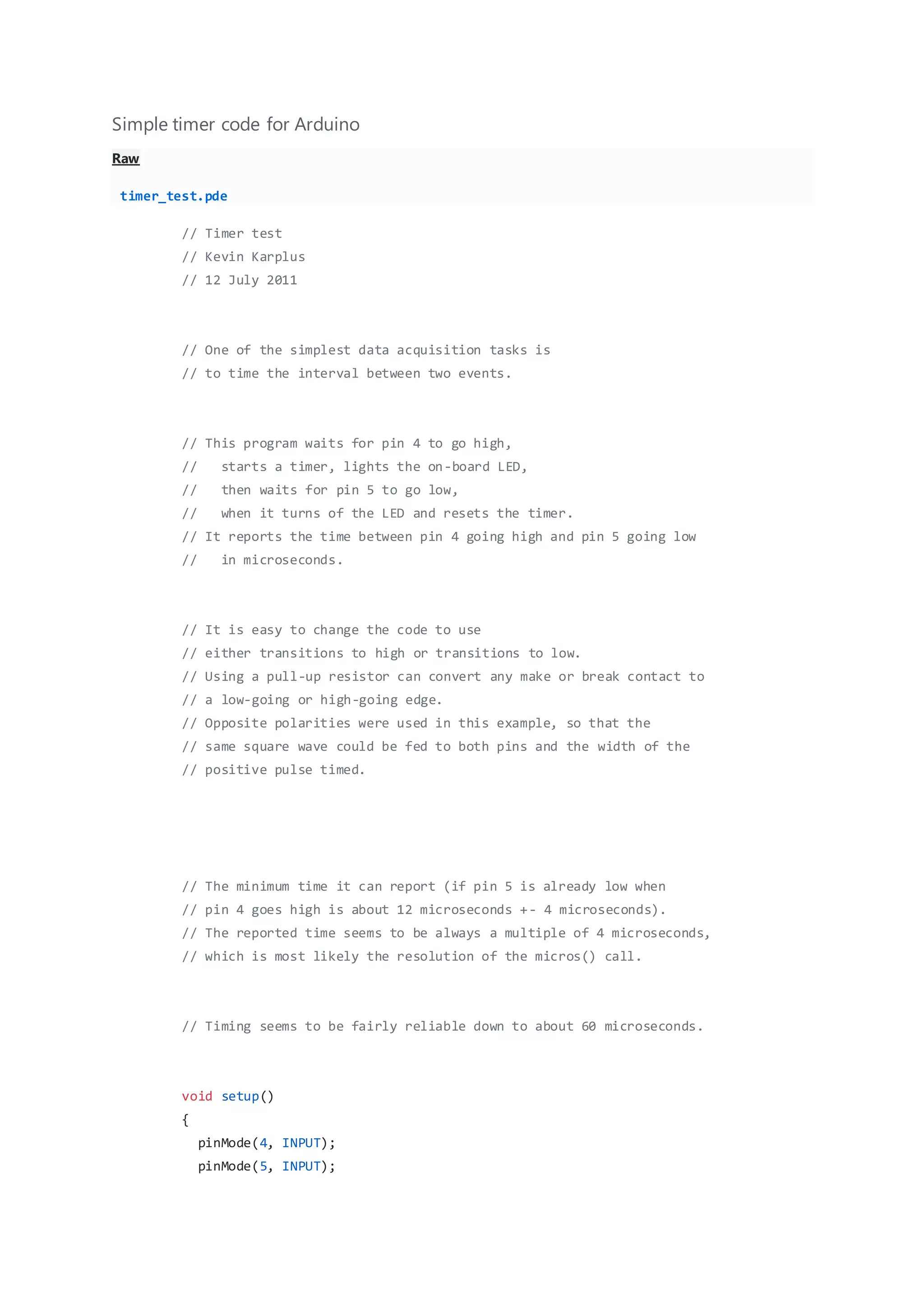
Simple timer code for Arduino
Raw
timer_test.pde
// Timer test
// Kevin Karplus
// 12 July 2011
// One of the simplest data acquisition tasks is
// to time the interval between two events.
// This program waits for pin 4 to go high,
// starts a timer, lights the on-board LED,
// then waits for pin 5 to go low,
// when it turns of the LED and resets the timer.
// It reports the time between pin 4 going high and pin 5 going low
// in microseconds.
// It is easy to change the code to use
// either transitions to high or transitions to low.
// Using a pull-up resistor can convert any make or break contact to
// a low-going or high-going edge.
// Opposite polarities were used in this example, so that the
// same square wave could be fed to both pins and the width of the
// positive pulse timed.
// The minimum time it can report (if pin 5 is already low when
// pin 4 goes high is about 12 microseconds +- 4 microseconds).
// The reported time seems to be always a multiple of 4 microseconds,
// which is most likely the resolution of the micros() call.
// Timing seems to be fairly reliable down to about 60 microseconds.
void setup()
{
pinMode(4, INPUT);
pinMode(5, INPUT);
pinMode(13, OUTPUT); // on-board LED
Serial.begin(115200);
}
void loop()
{
unsigned long start_time;
unsigned long stop_time;
digitalWrite(13,0); // Turn LED off
while(digitalRead(4)==0) {}
start_time=micros();
digitalWrite(13,1); // Turn LED on
while (digitalRead(5)) {}
stop_time=micros();
digitalWrite(13,0);
Serial.print("time hi->lo=");
Serial.print(stop_time-start_time);
Serial.println(" microsec");
delay(500);
}

Simple timer code for arduino

  • 1.
    Simple timer codefor Arduino Raw timer_test.pde // Timer test // Kevin Karplus // 12 July 2011 // One of the simplest data acquisition tasks is // to time the interval between two events. // This program waits for pin 4 to go high, // starts a timer, lights the on-board LED, // then waits for pin 5 to go low, // when it turns of the LED and resets the timer. // It reports the time between pin 4 going high and pin 5 going low // in microseconds. // It is easy to change the code to use // either transitions to high or transitions to low. // Using a pull-up resistor can convert any make or break contact to // a low-going or high-going edge. // Opposite polarities were used in this example, so that the // same square wave could be fed to both pins and the width of the // positive pulse timed. // The minimum time it can report (if pin 5 is already low when // pin 4 goes high is about 12 microseconds +- 4 microseconds). // The reported time seems to be always a multiple of 4 microseconds, // which is most likely the resolution of the micros() call. // Timing seems to be fairly reliable down to about 60 microseconds. void setup() { pinMode(4, INPUT); pinMode(5, INPUT);
  • 2.
    pinMode(13, OUTPUT); //on-board LED Serial.begin(115200); } void loop() { unsigned long start_time; unsigned long stop_time; digitalWrite(13,0); // Turn LED off while(digitalRead(4)==0) {} start_time=micros(); digitalWrite(13,1); // Turn LED on while (digitalRead(5)) {} stop_time=micros(); digitalWrite(13,0); Serial.print("time hi->lo="); Serial.print(stop_time-start_time); Serial.println(" microsec"); delay(500); }