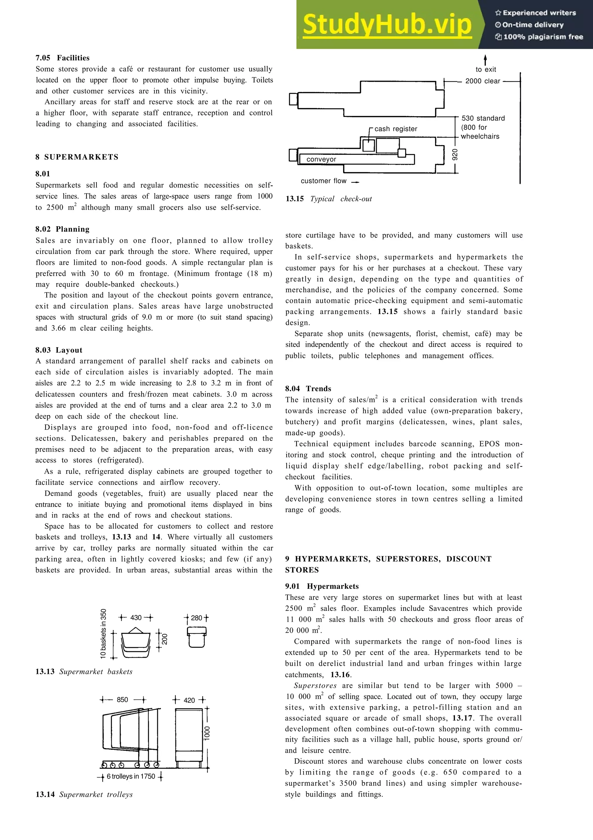
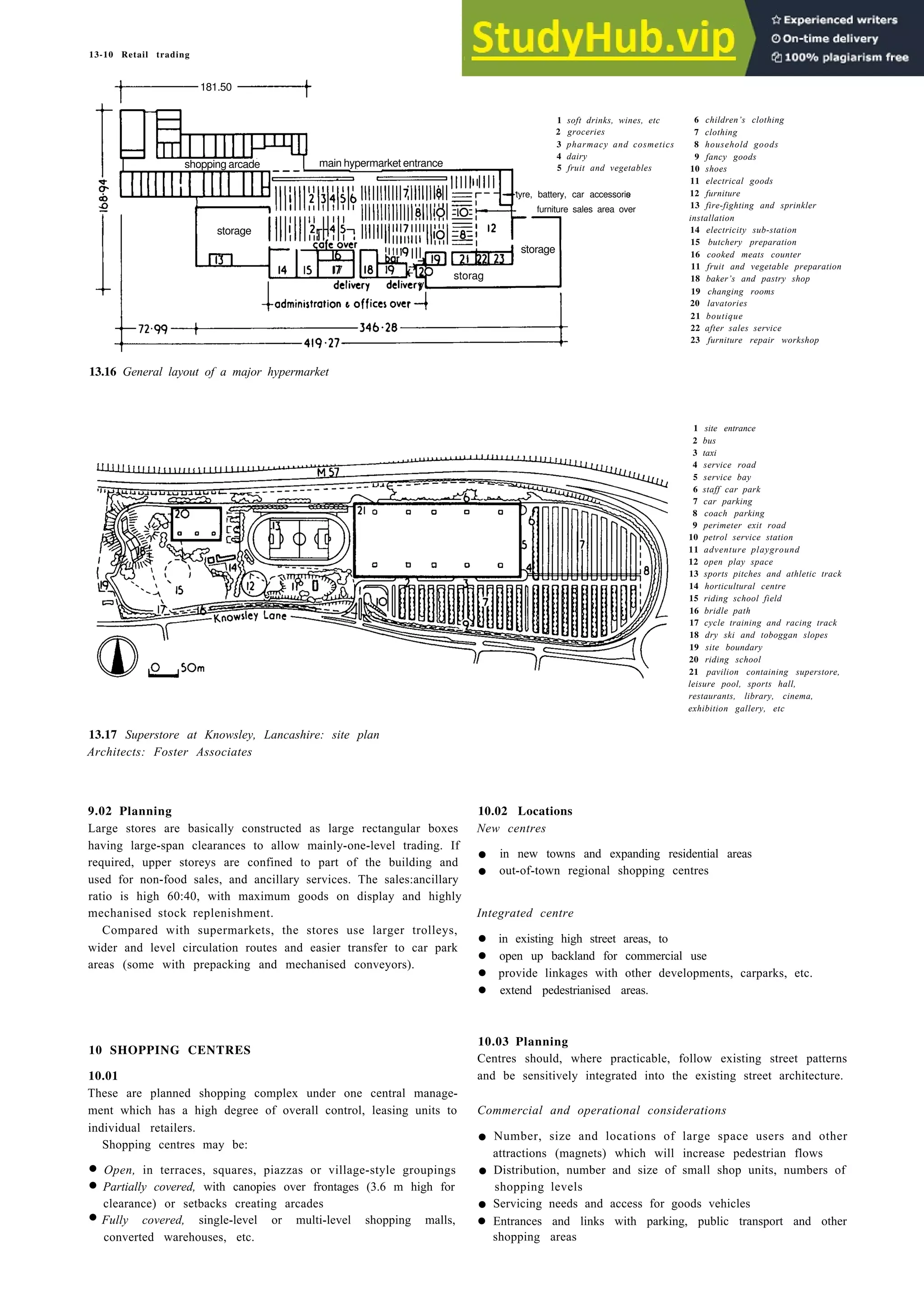
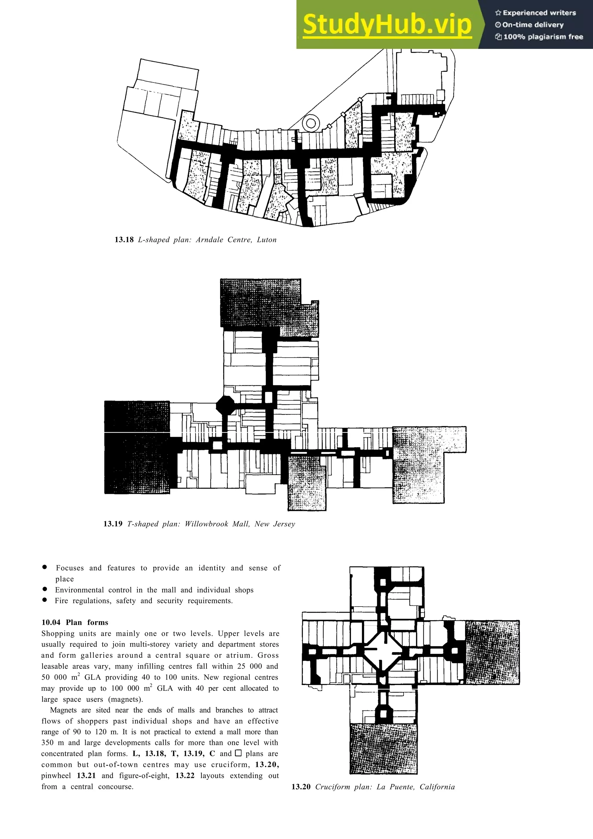
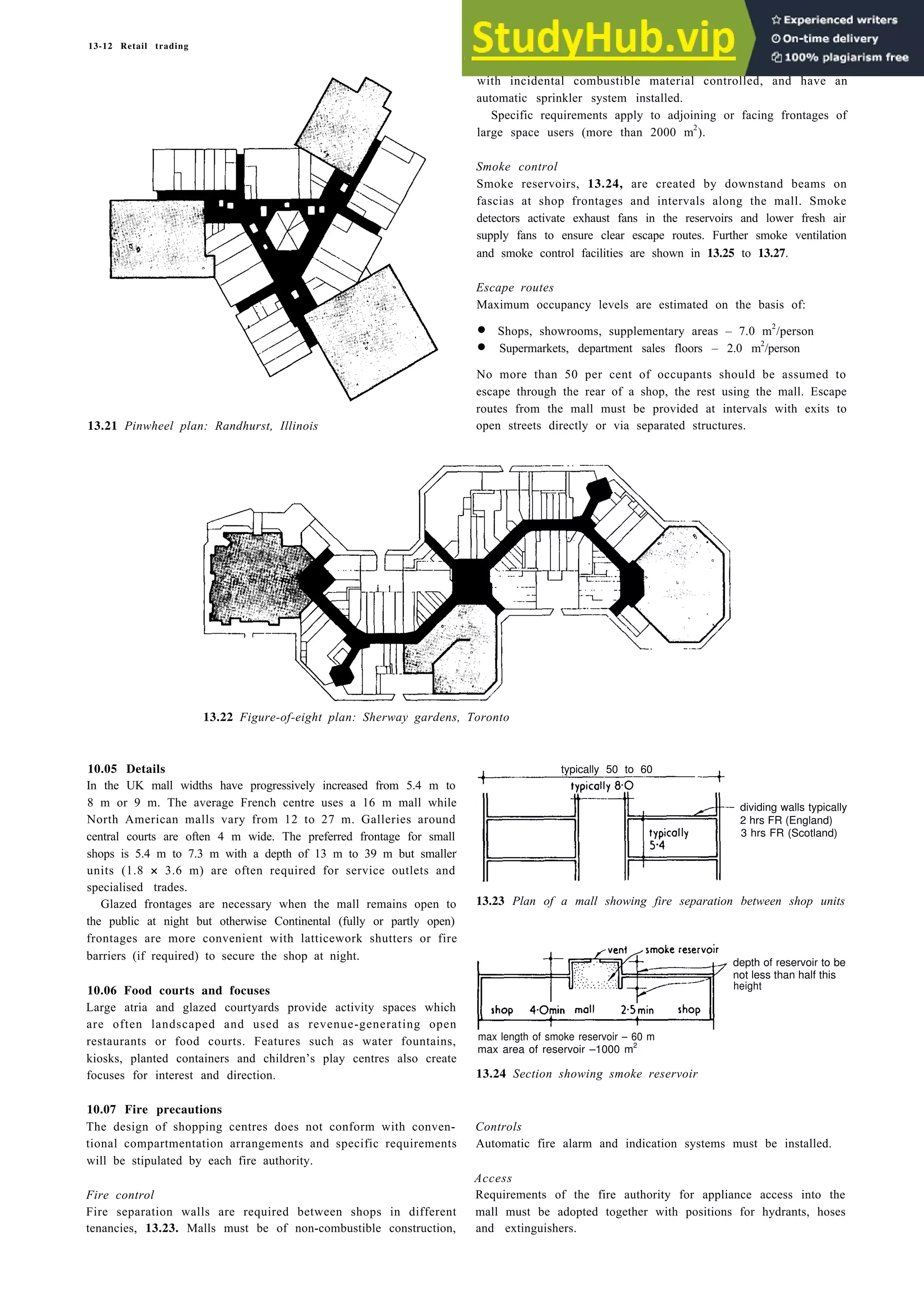
Download to read offline


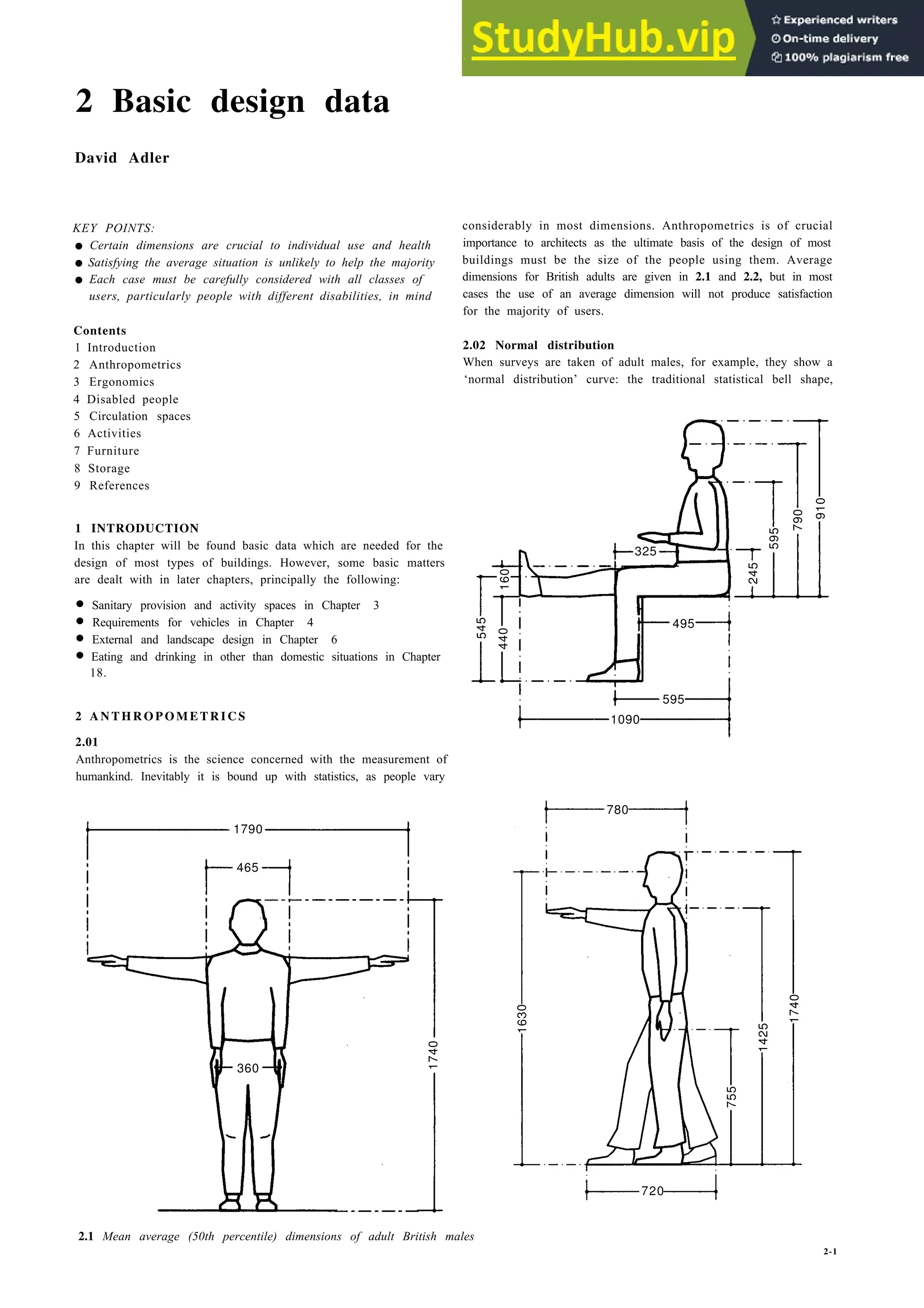
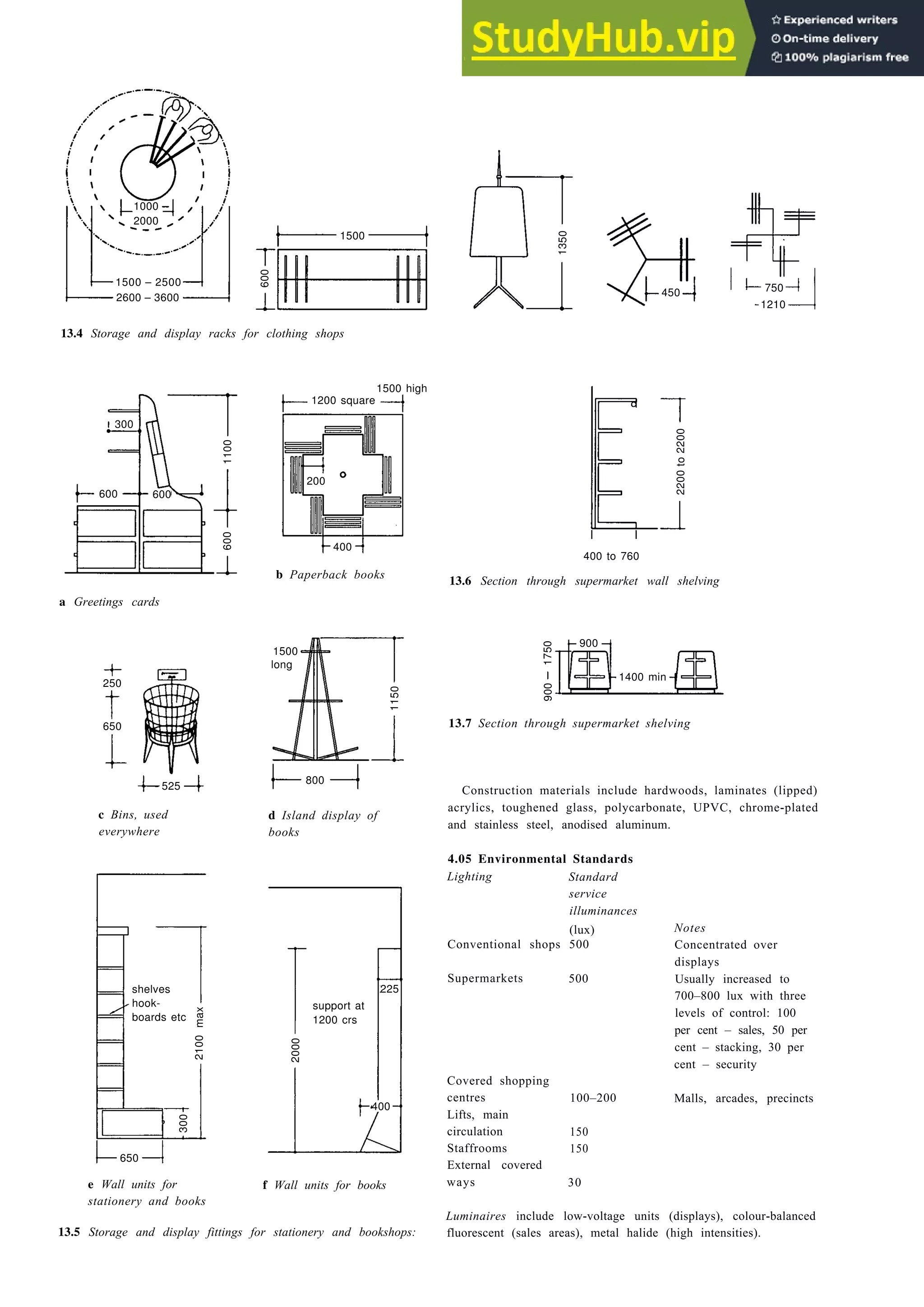
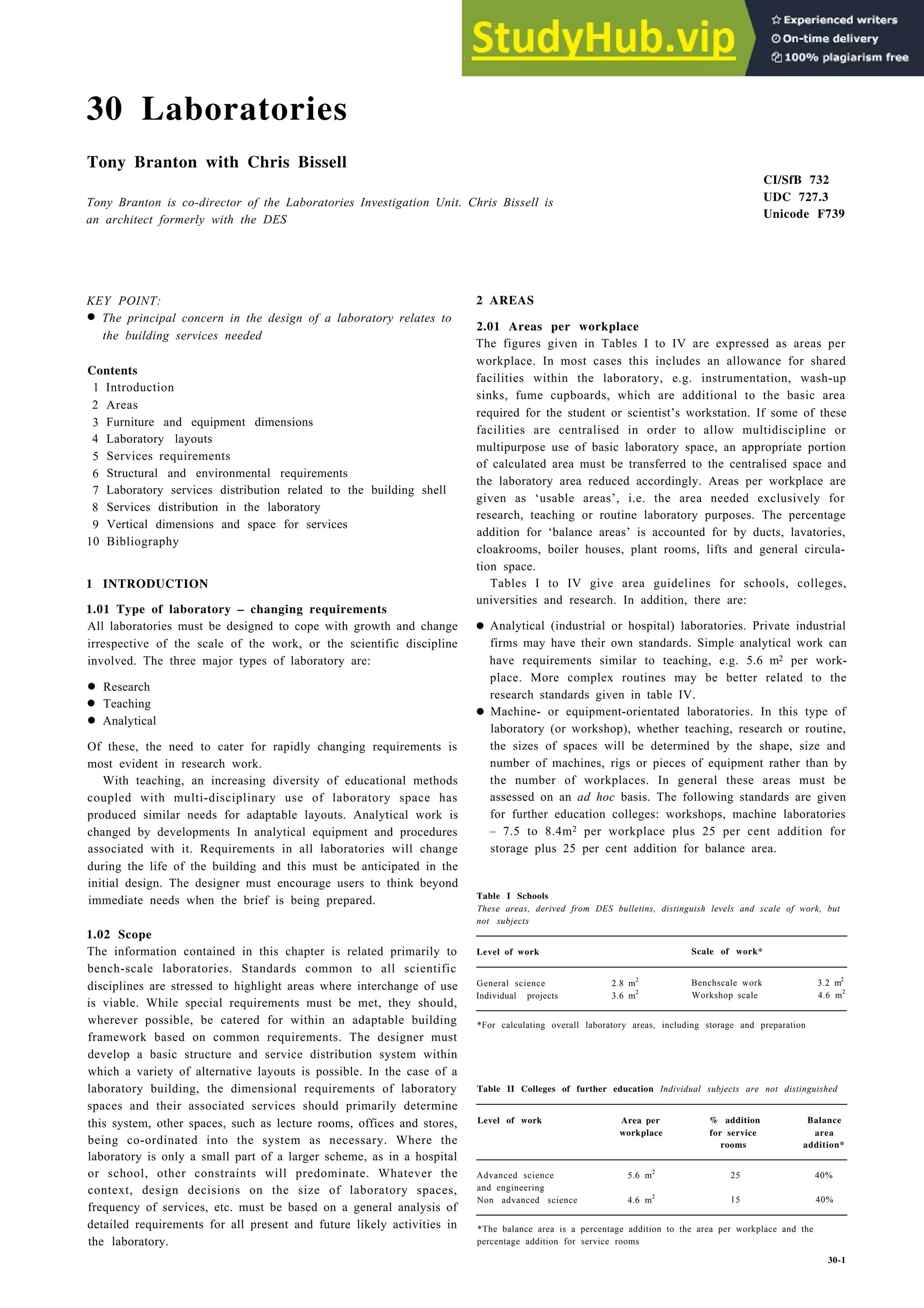
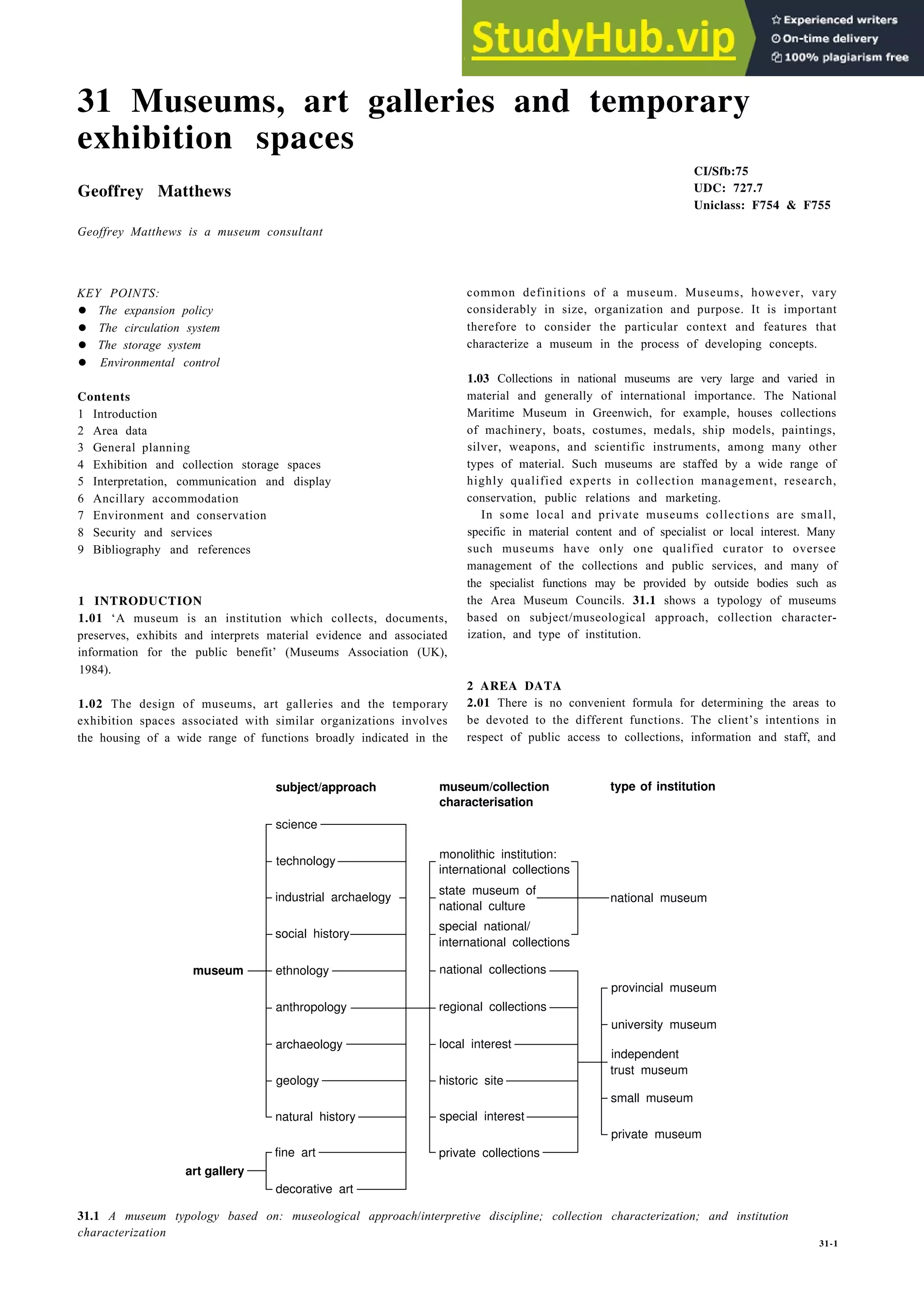
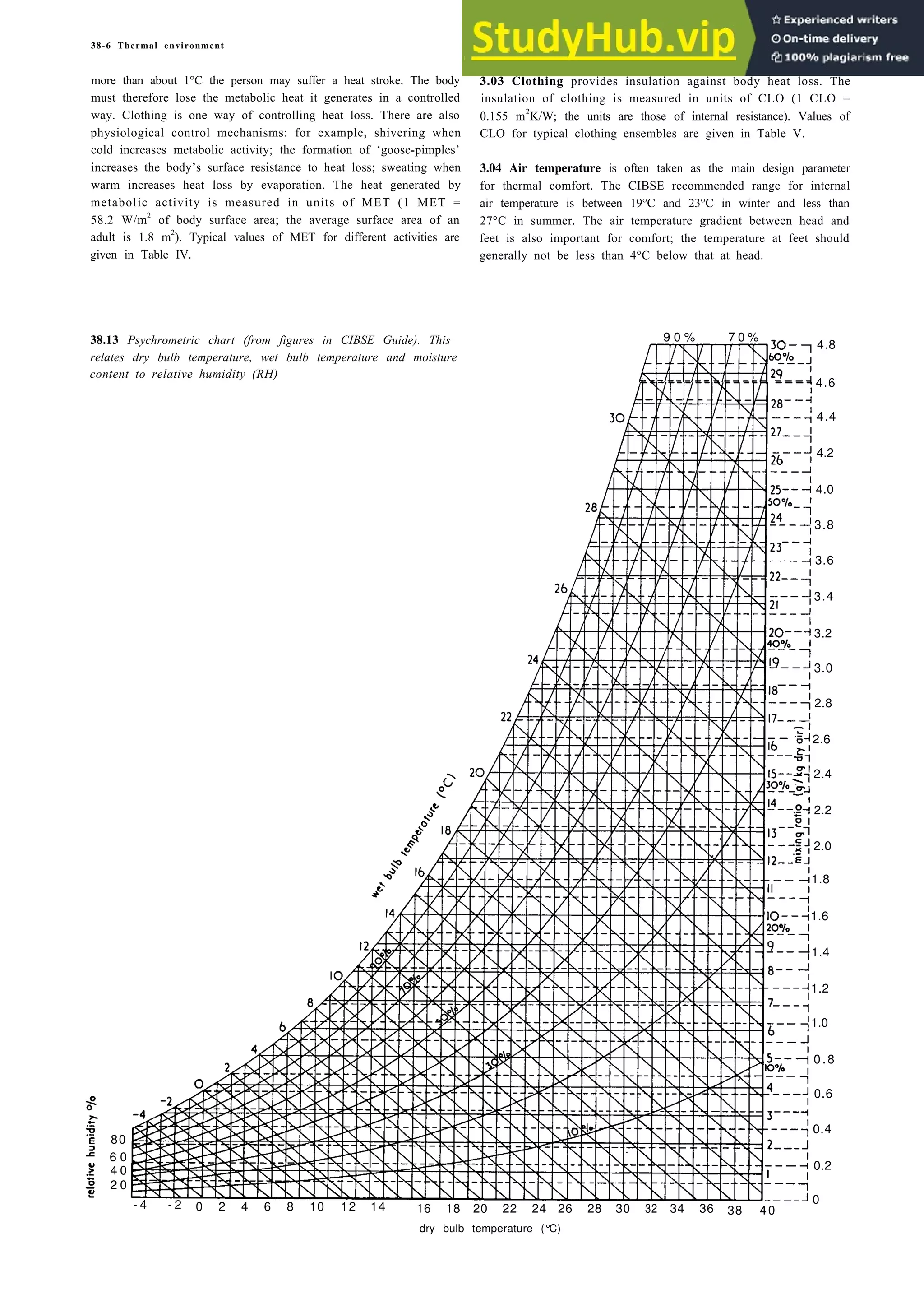
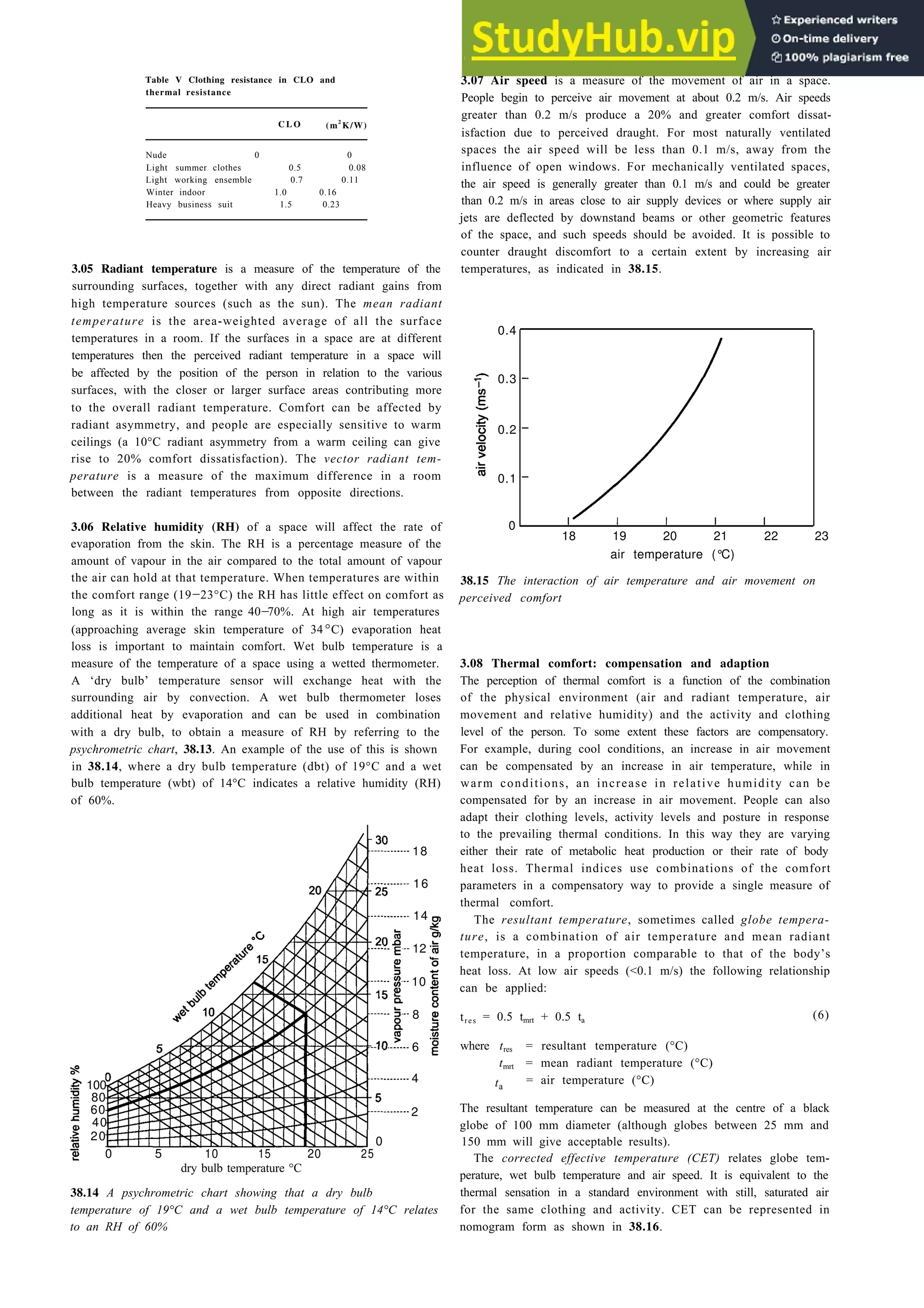
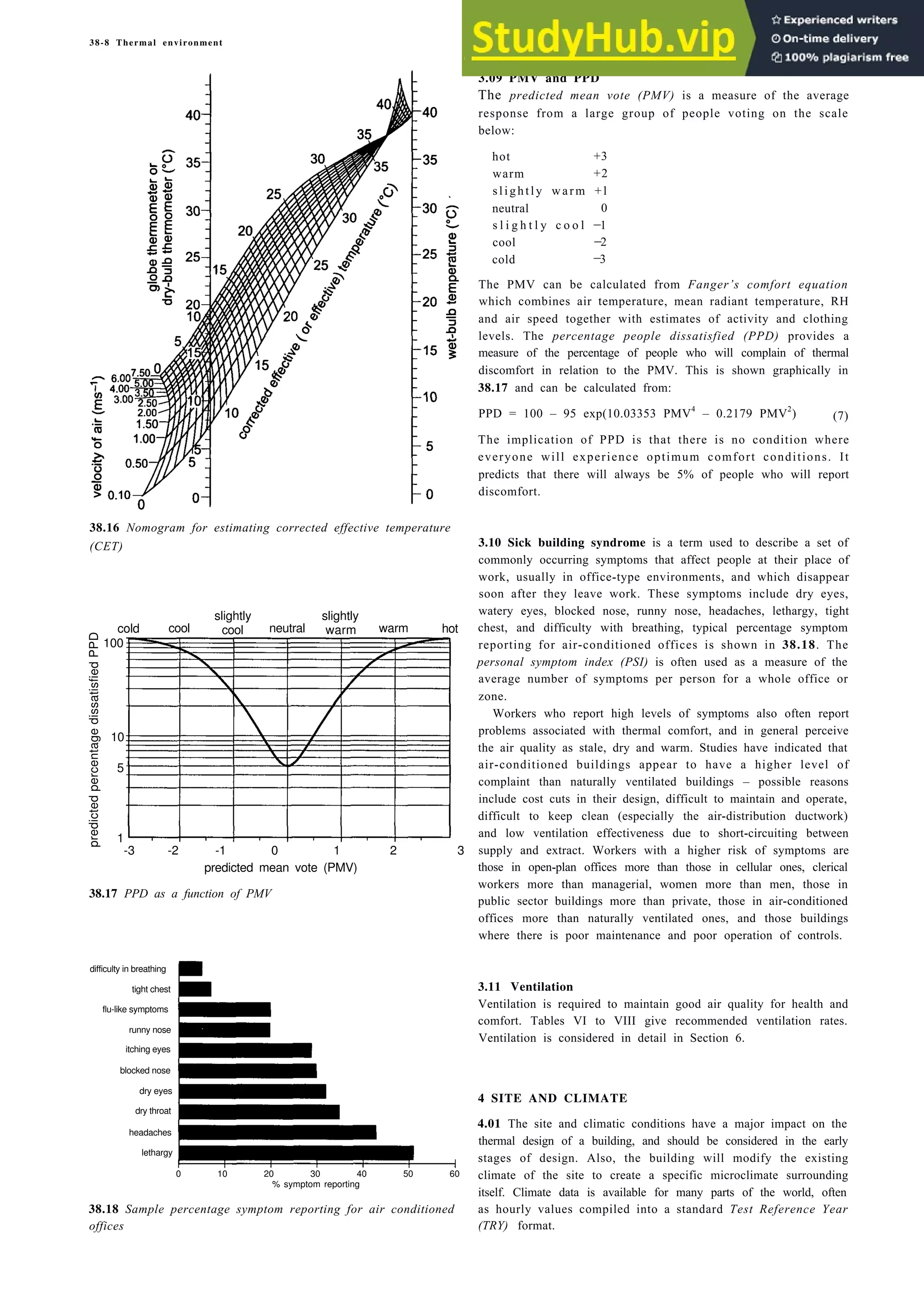
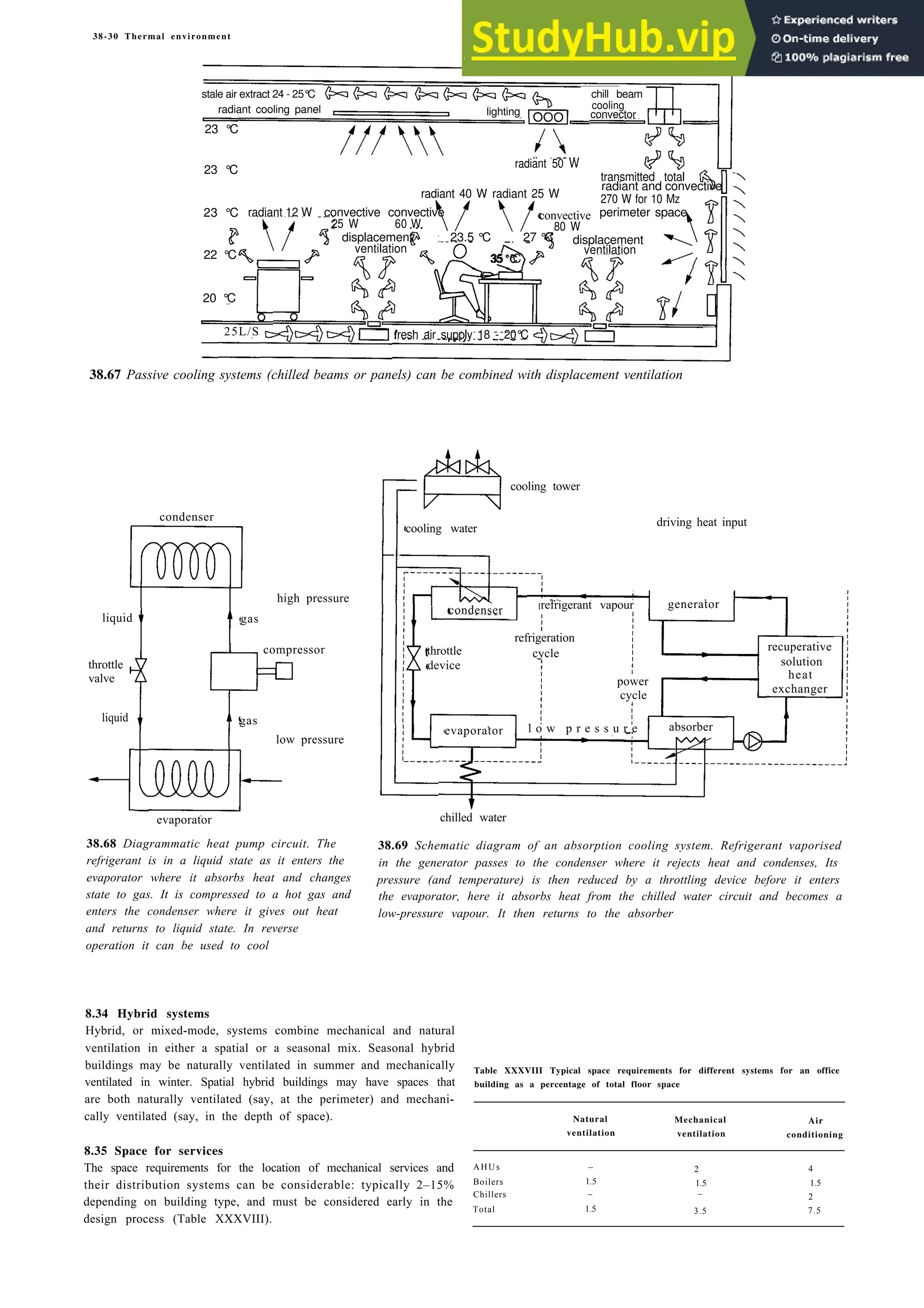
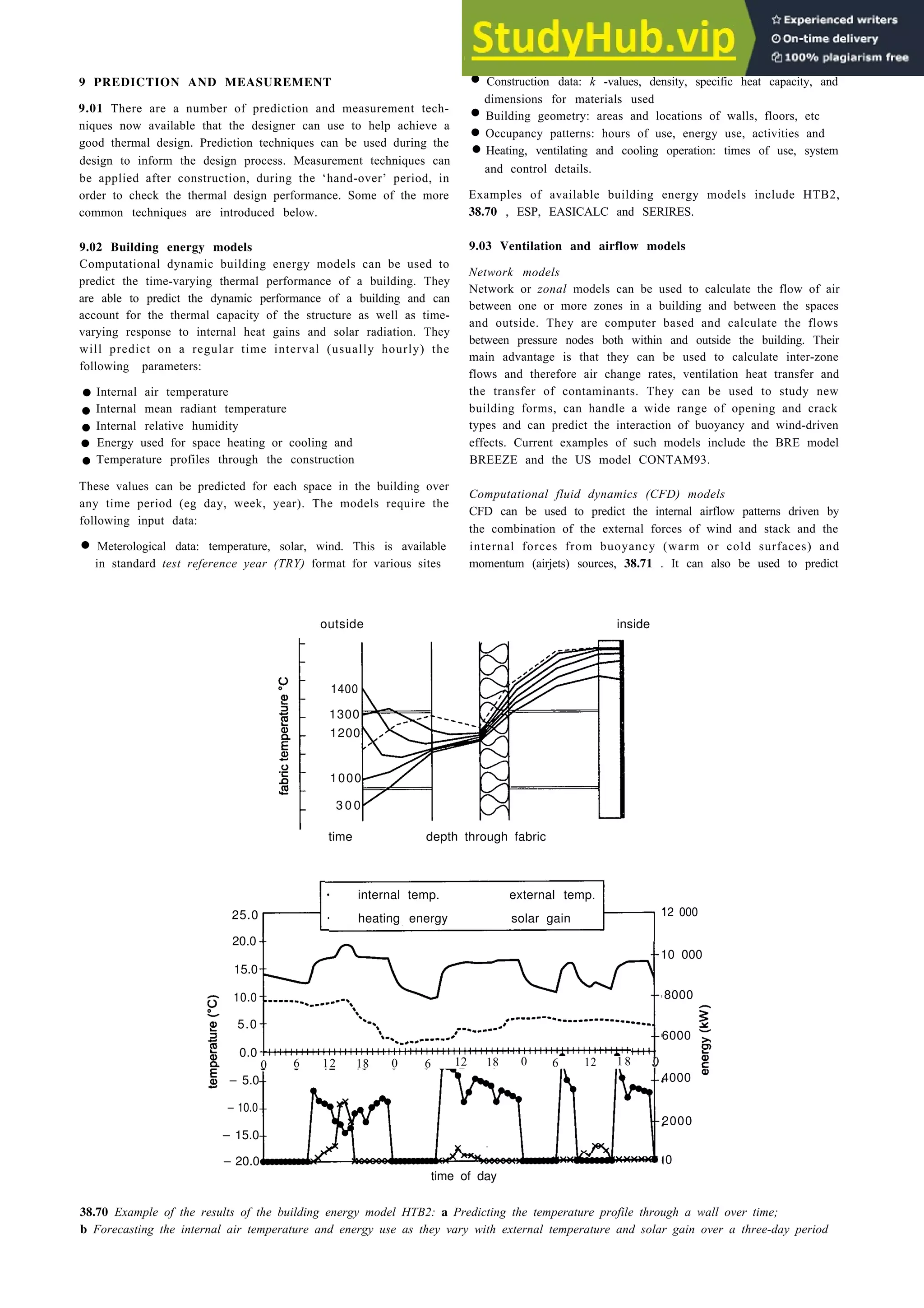
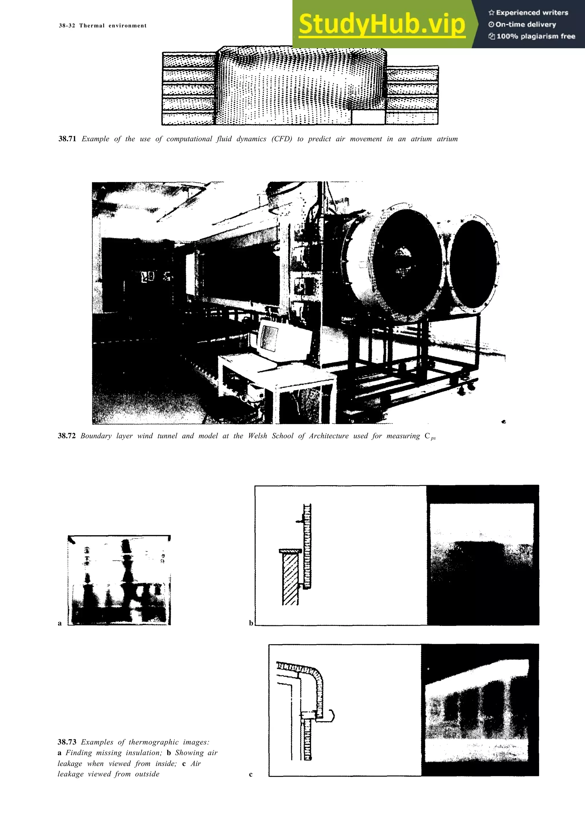
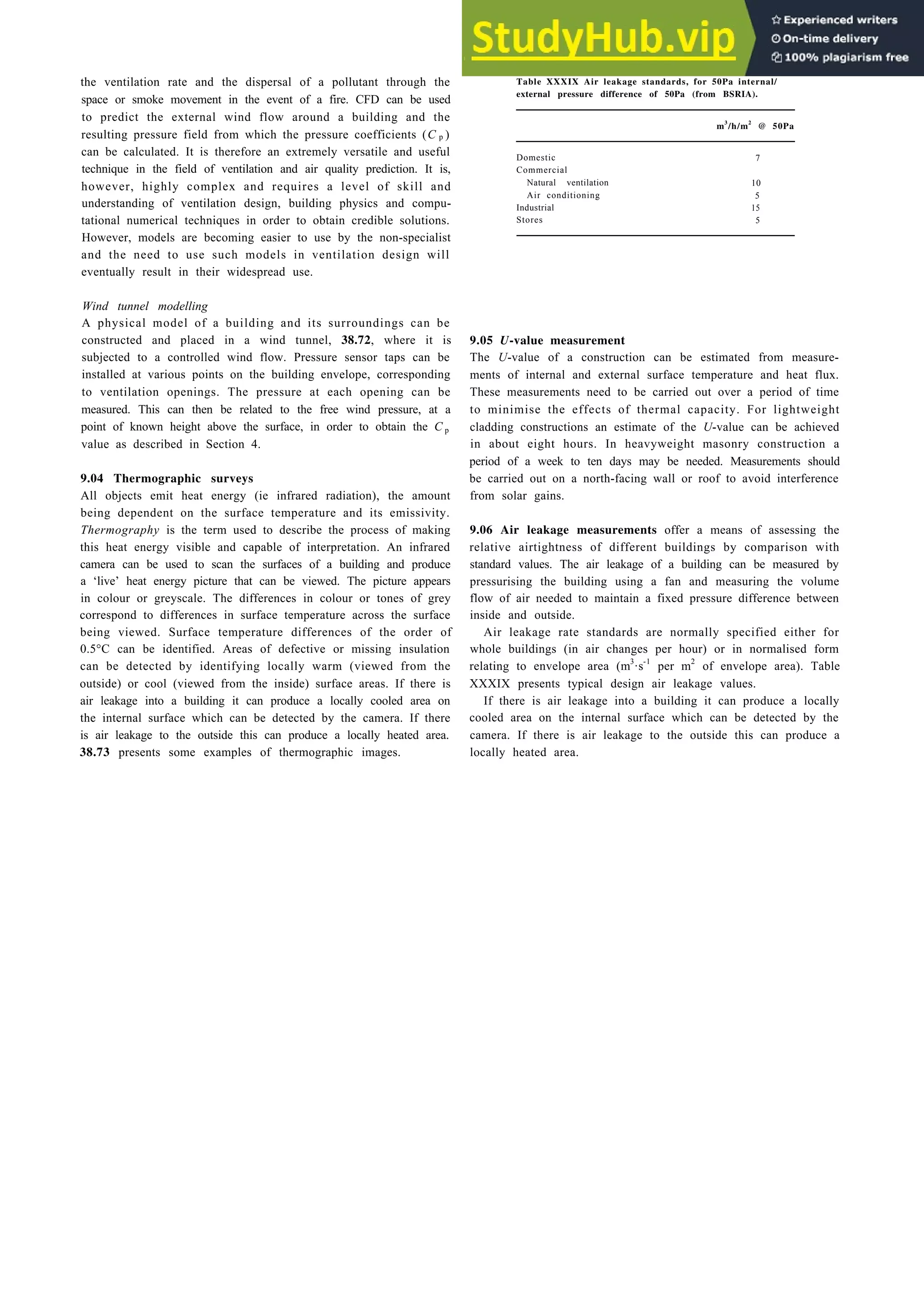
![2-6 Basic design data
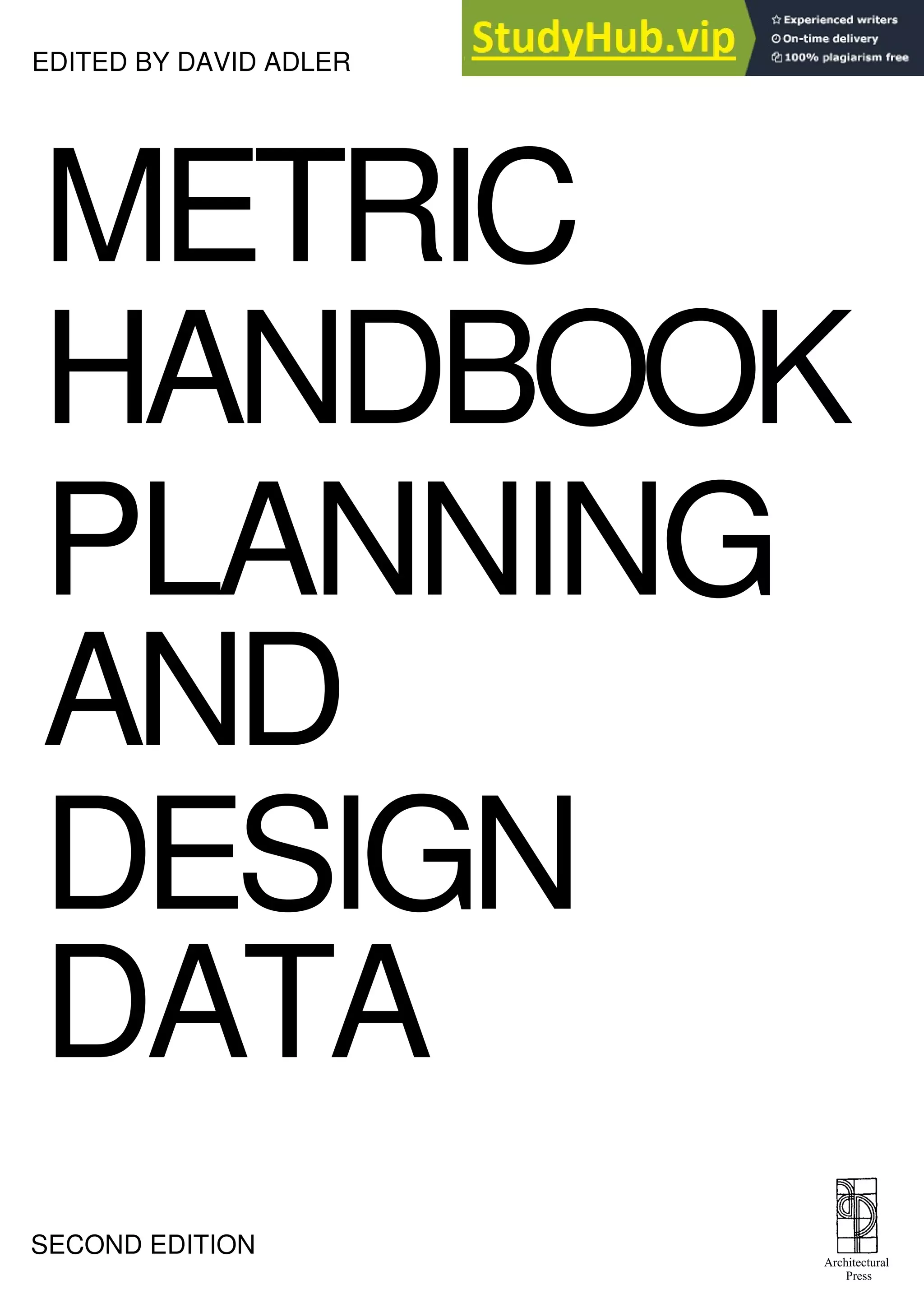
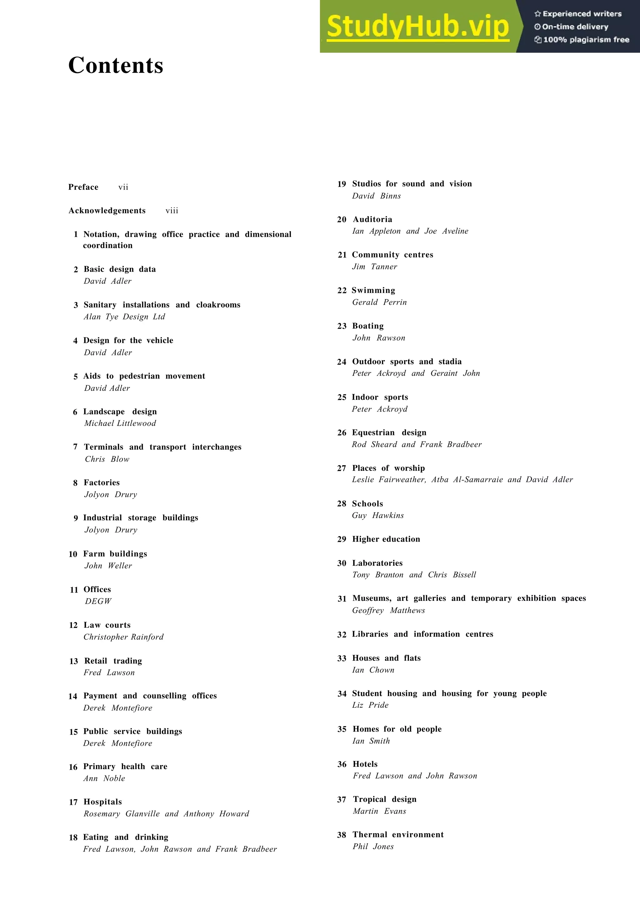
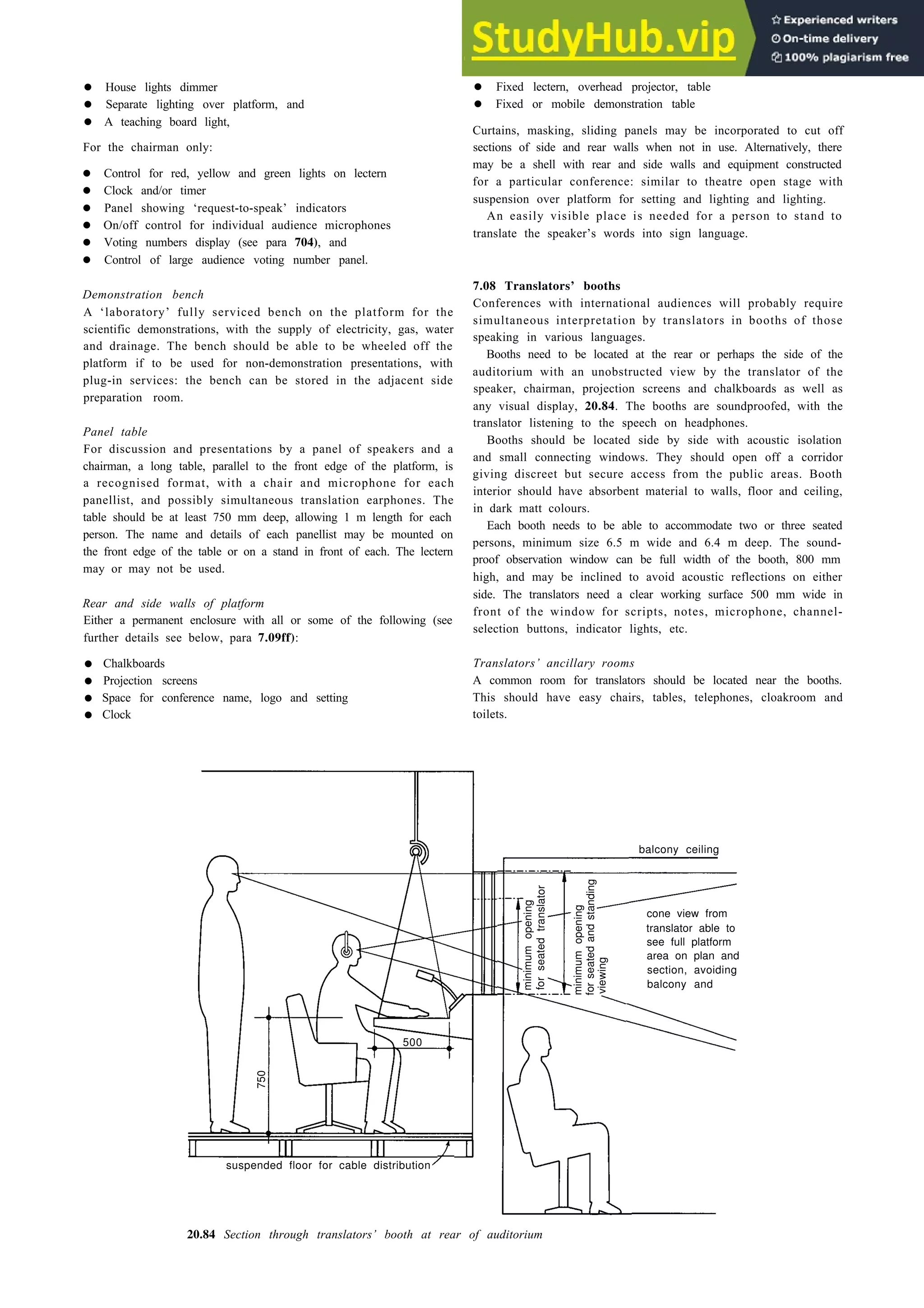
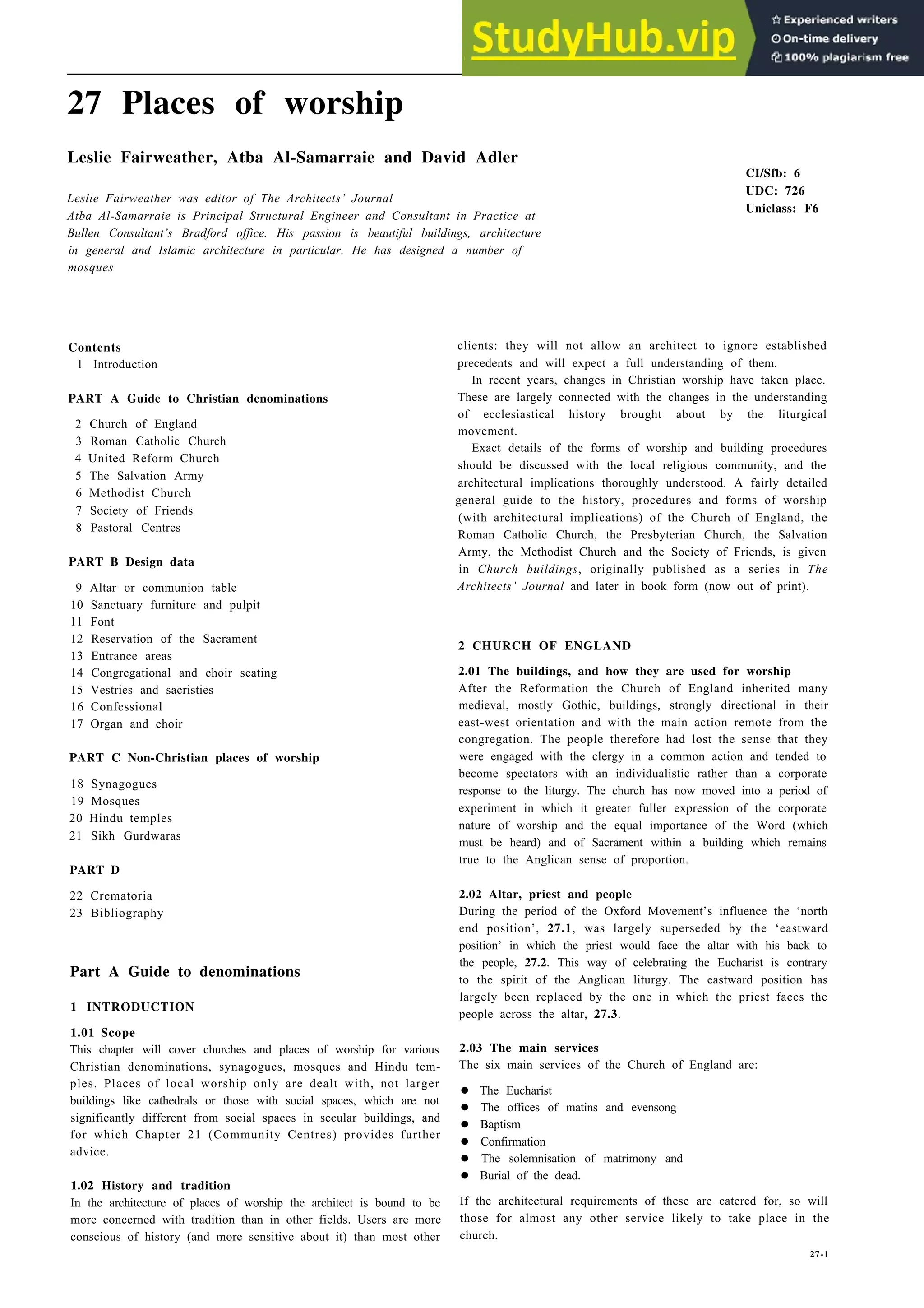
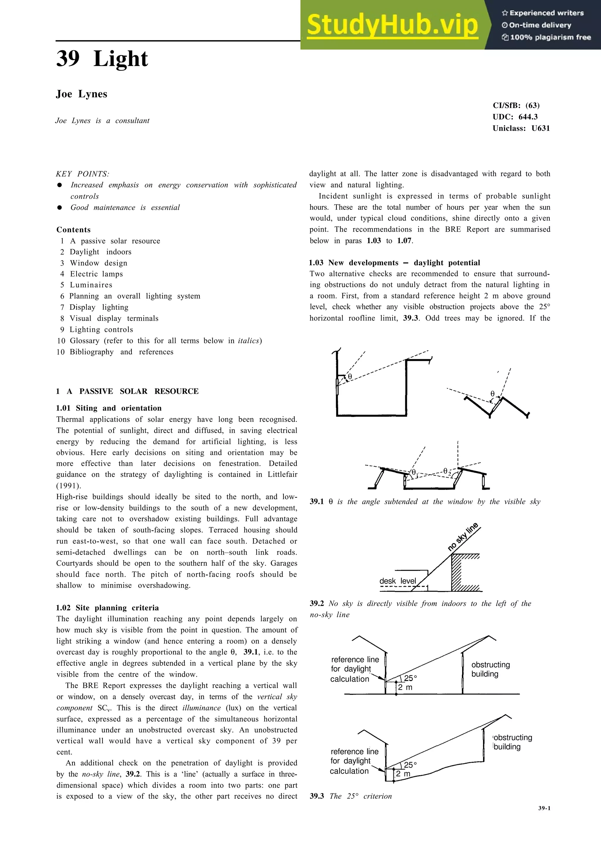
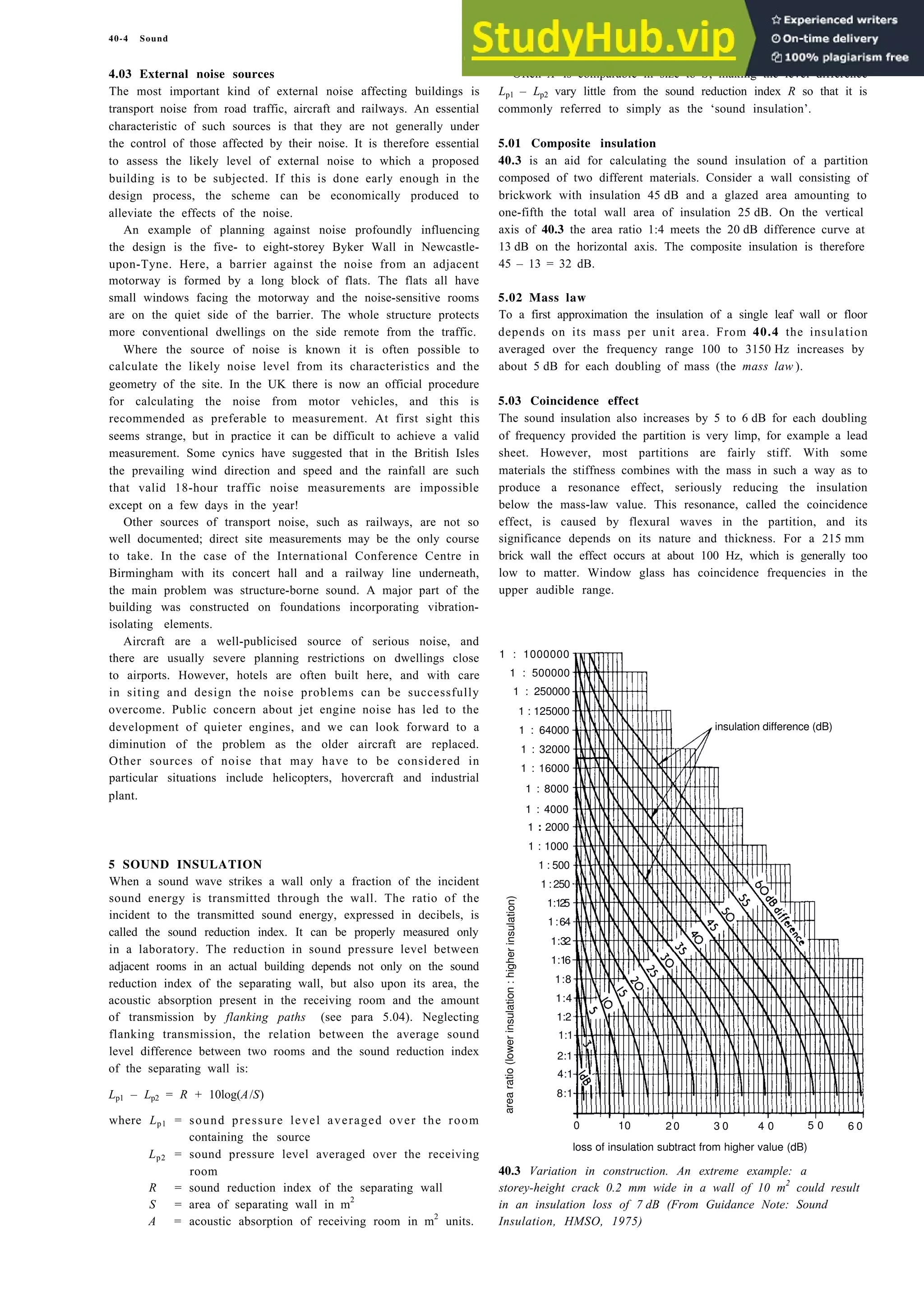
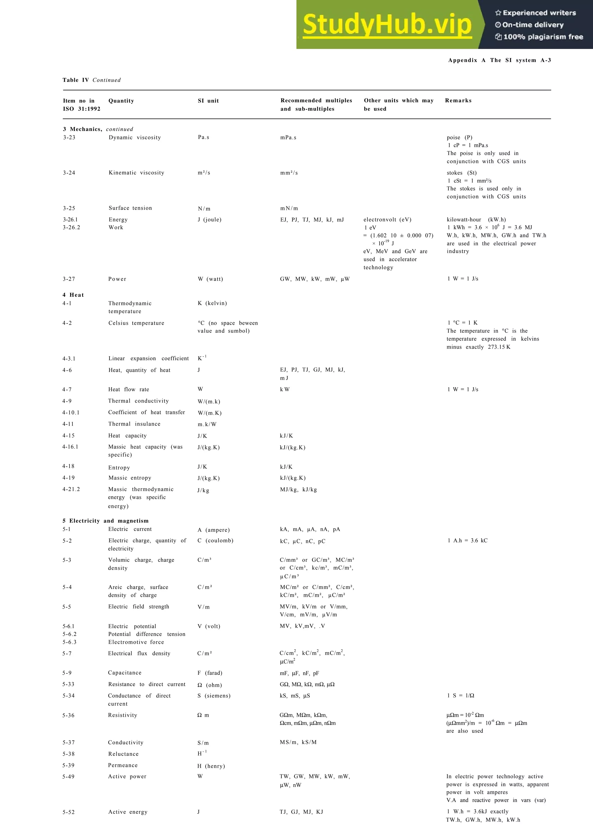
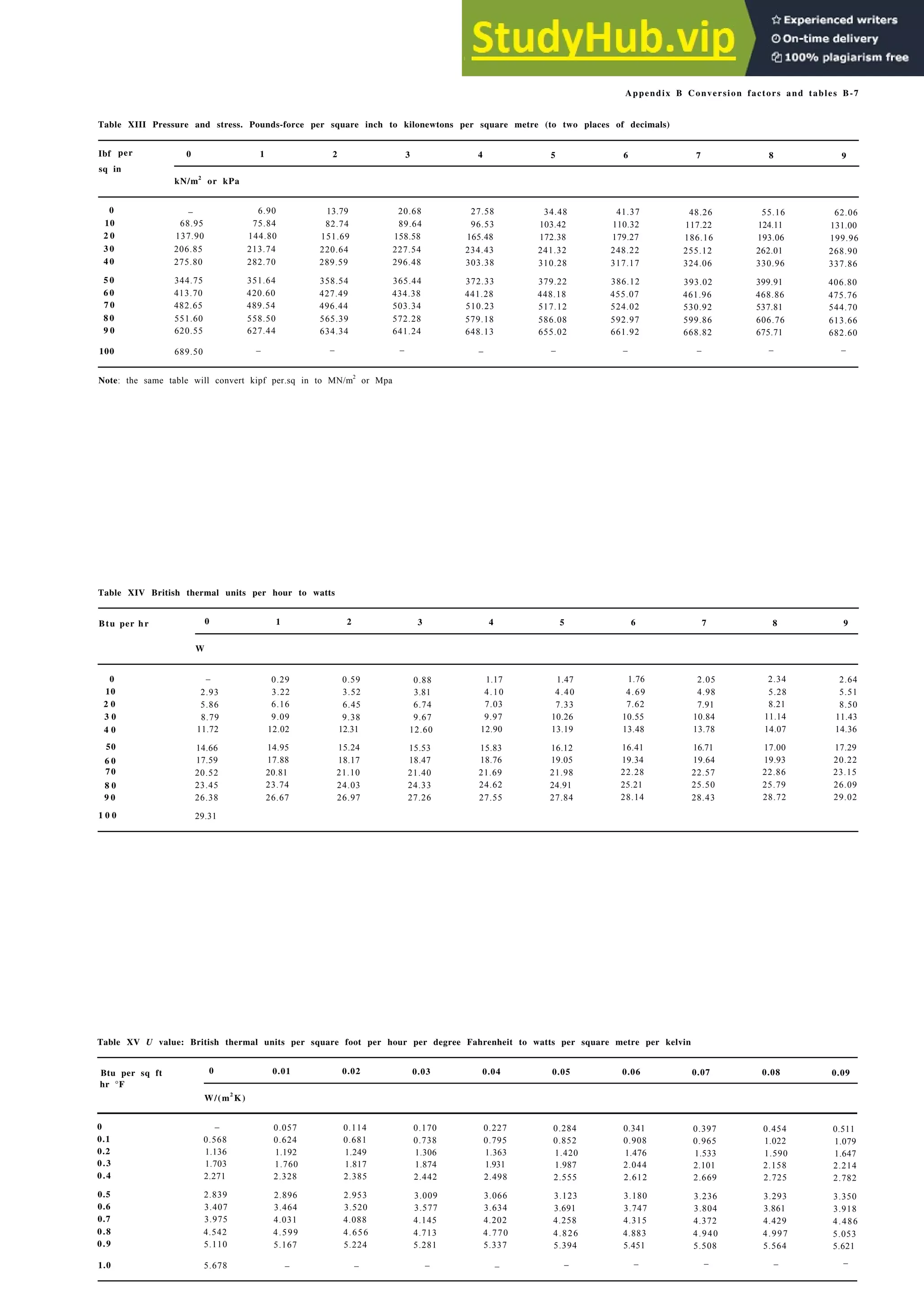
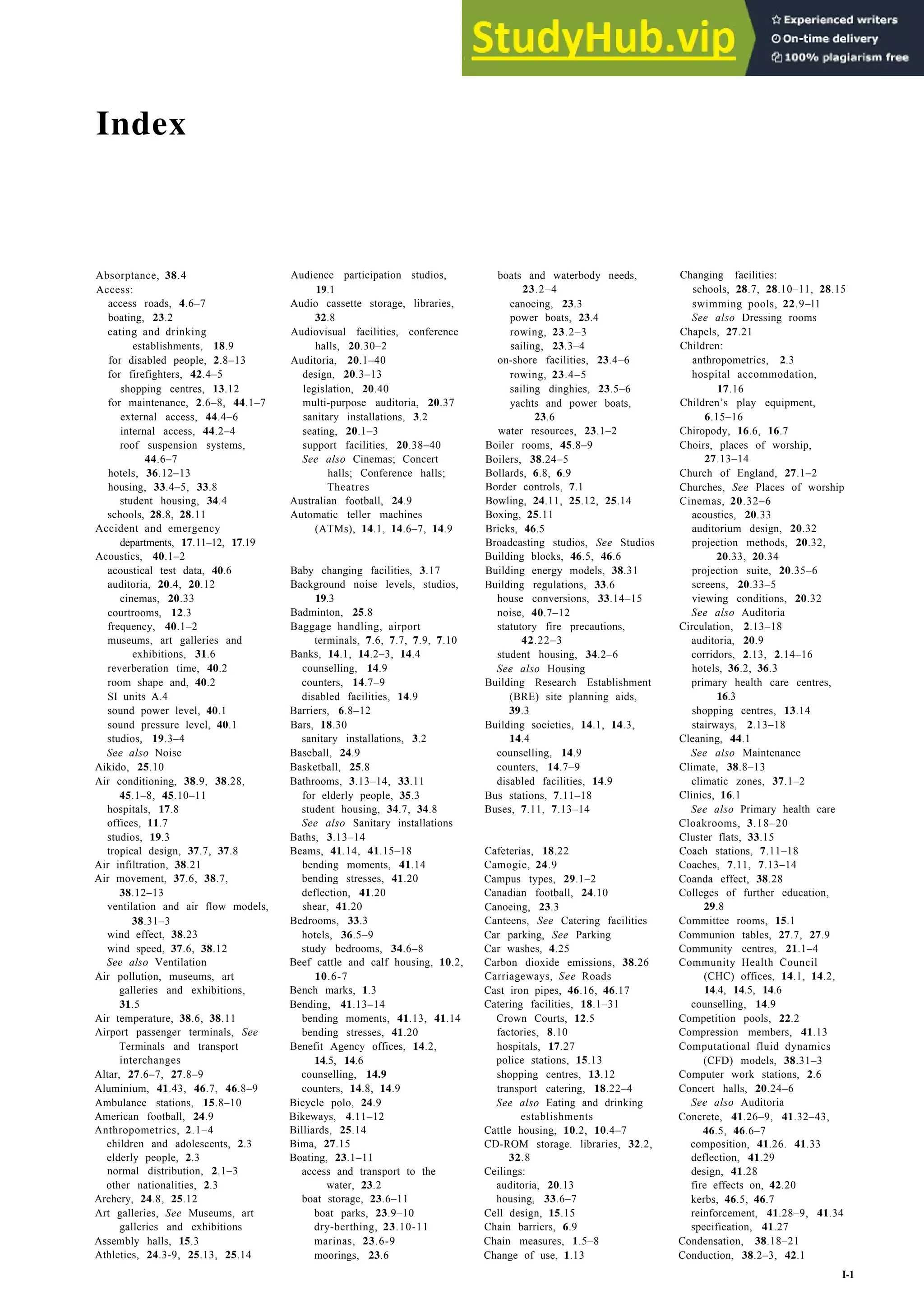
2.8 a Computer workstation
5
4
3
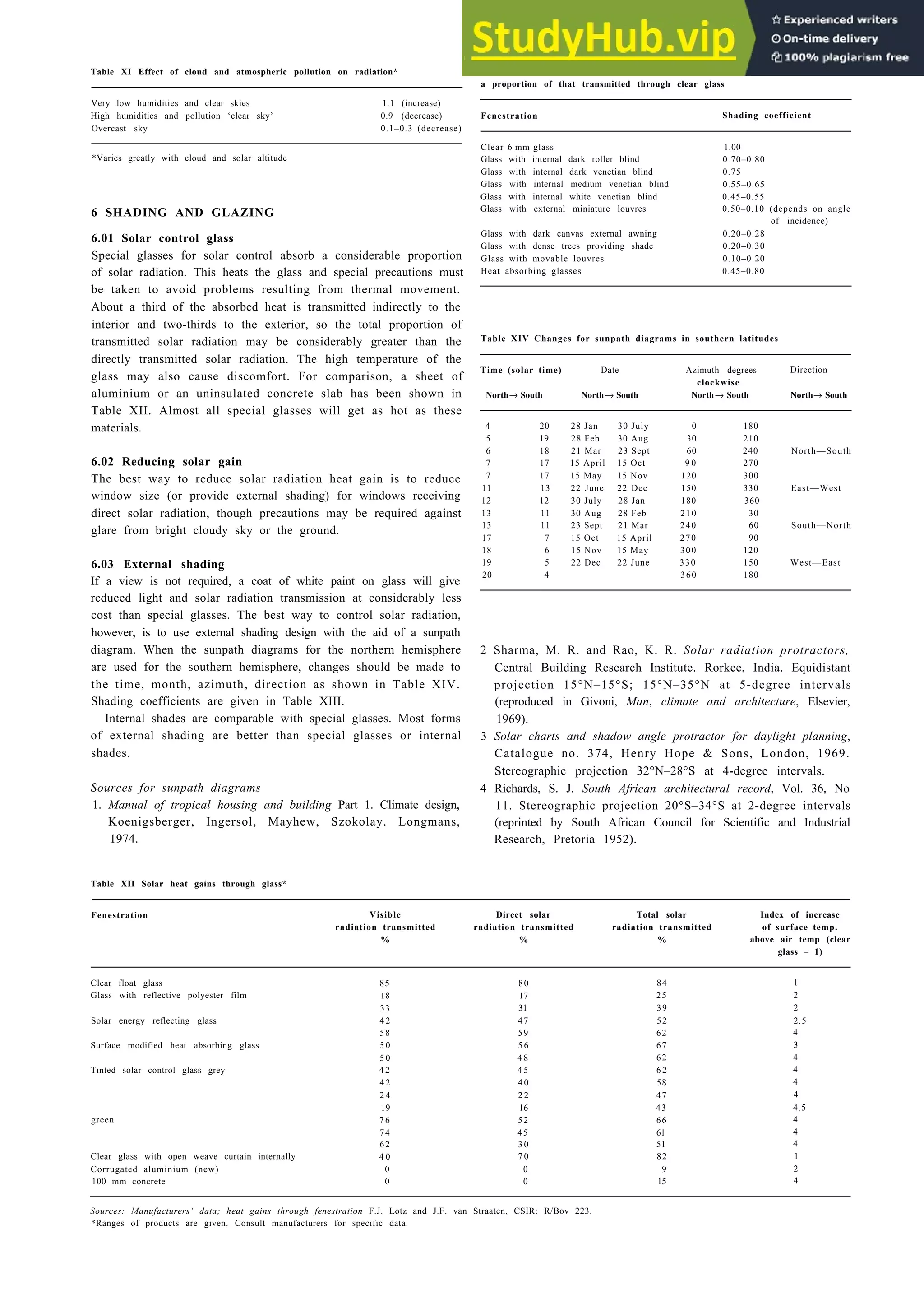
2
1
character
height
(mm)
200 400 600 800 1000 1200
viewing distance (mm)
b Viewing distance
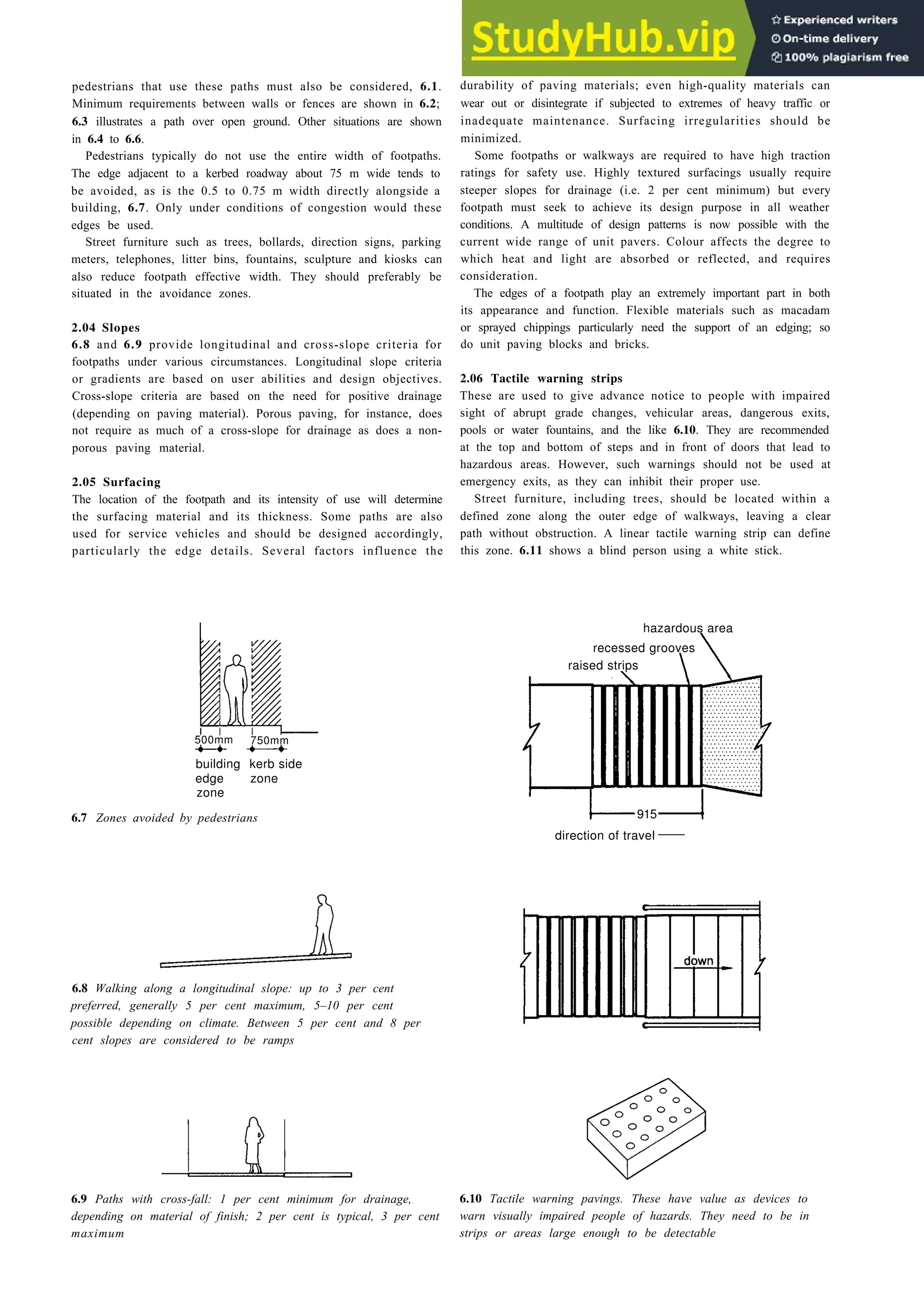
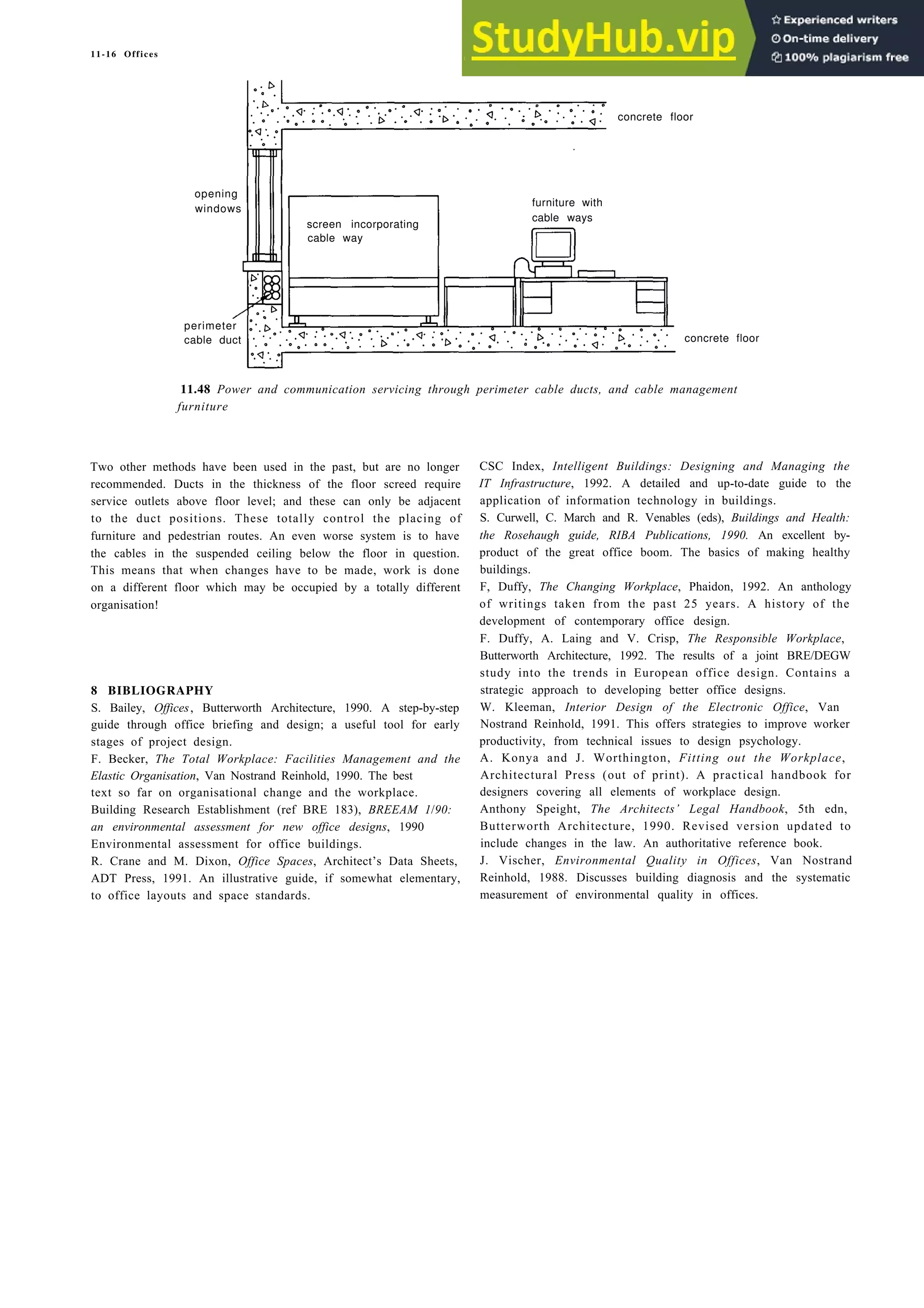
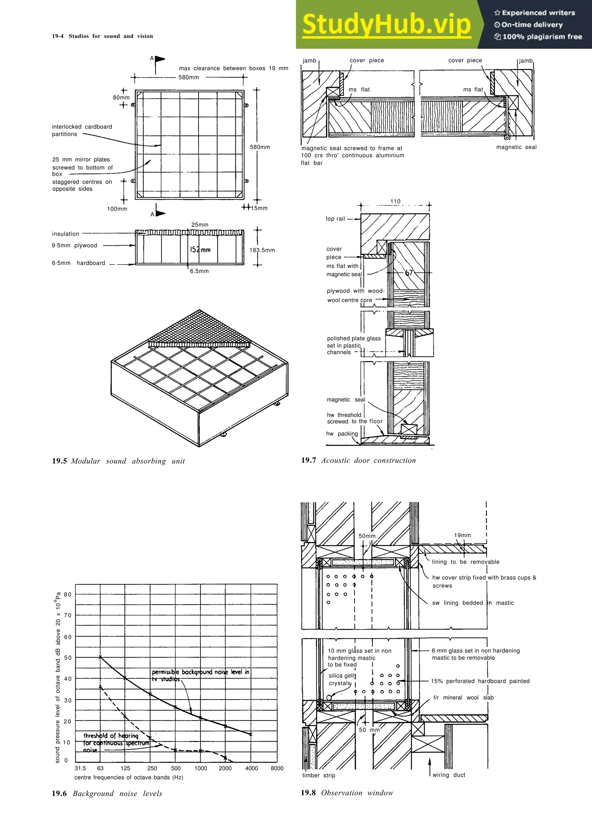
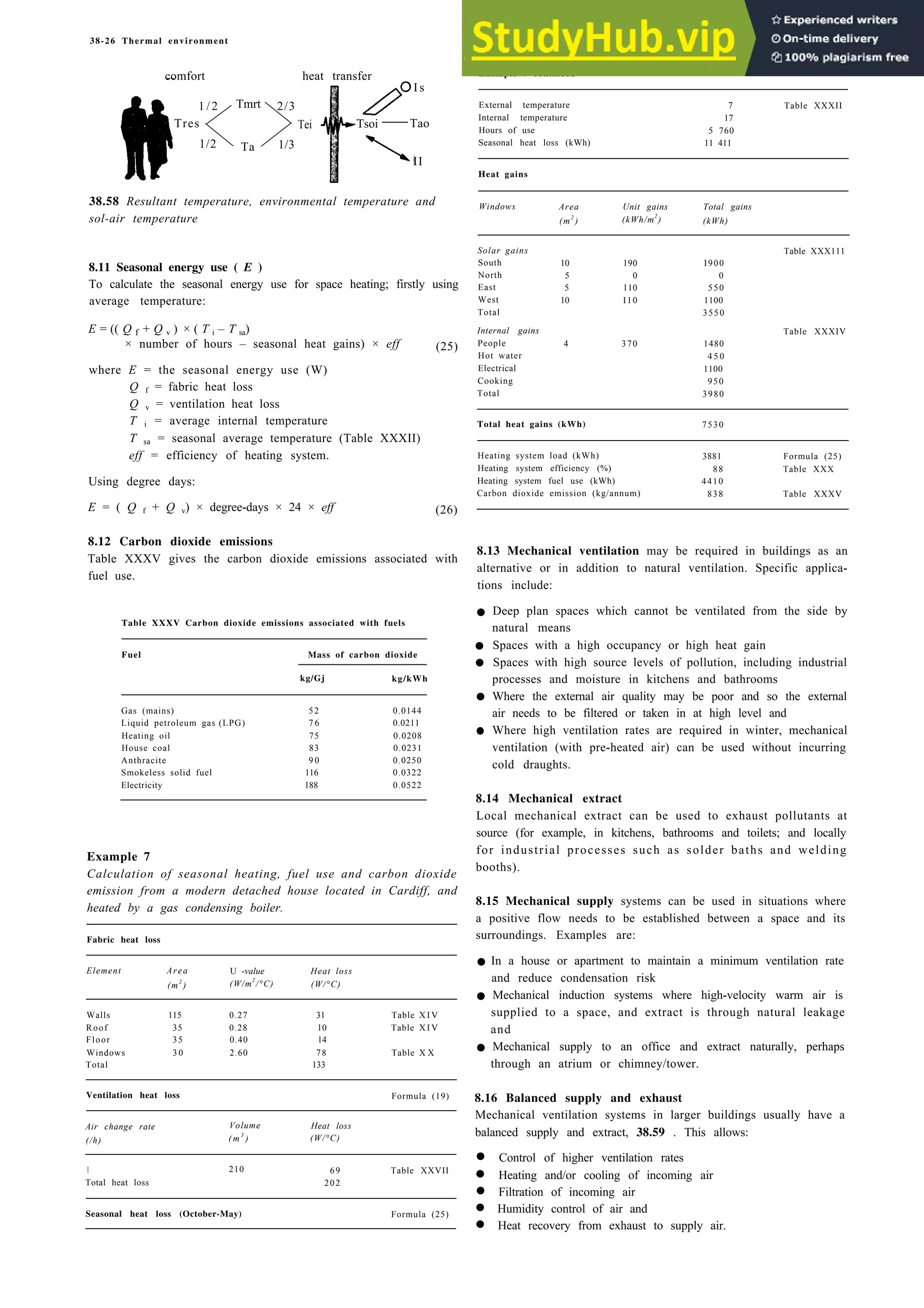
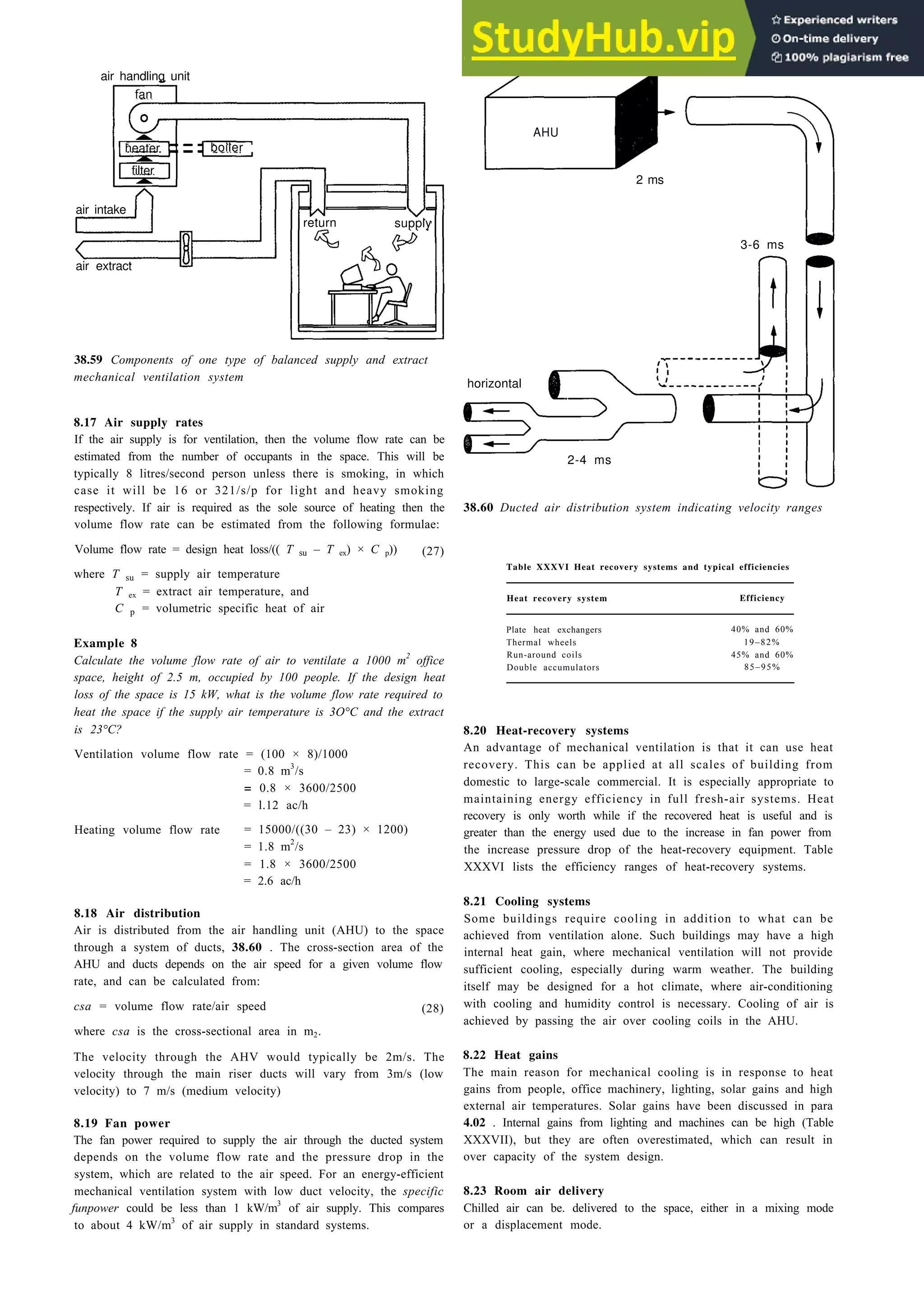
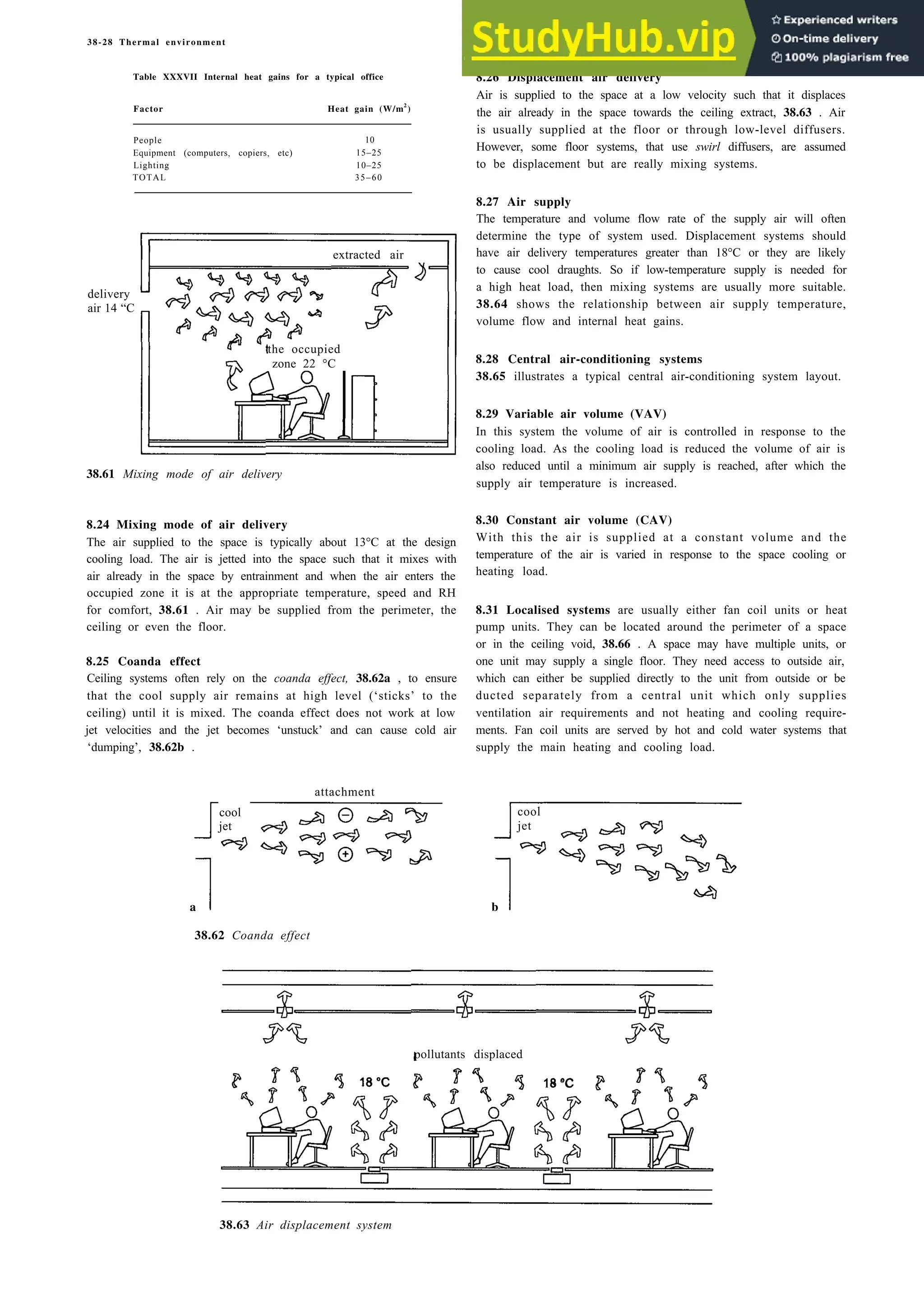
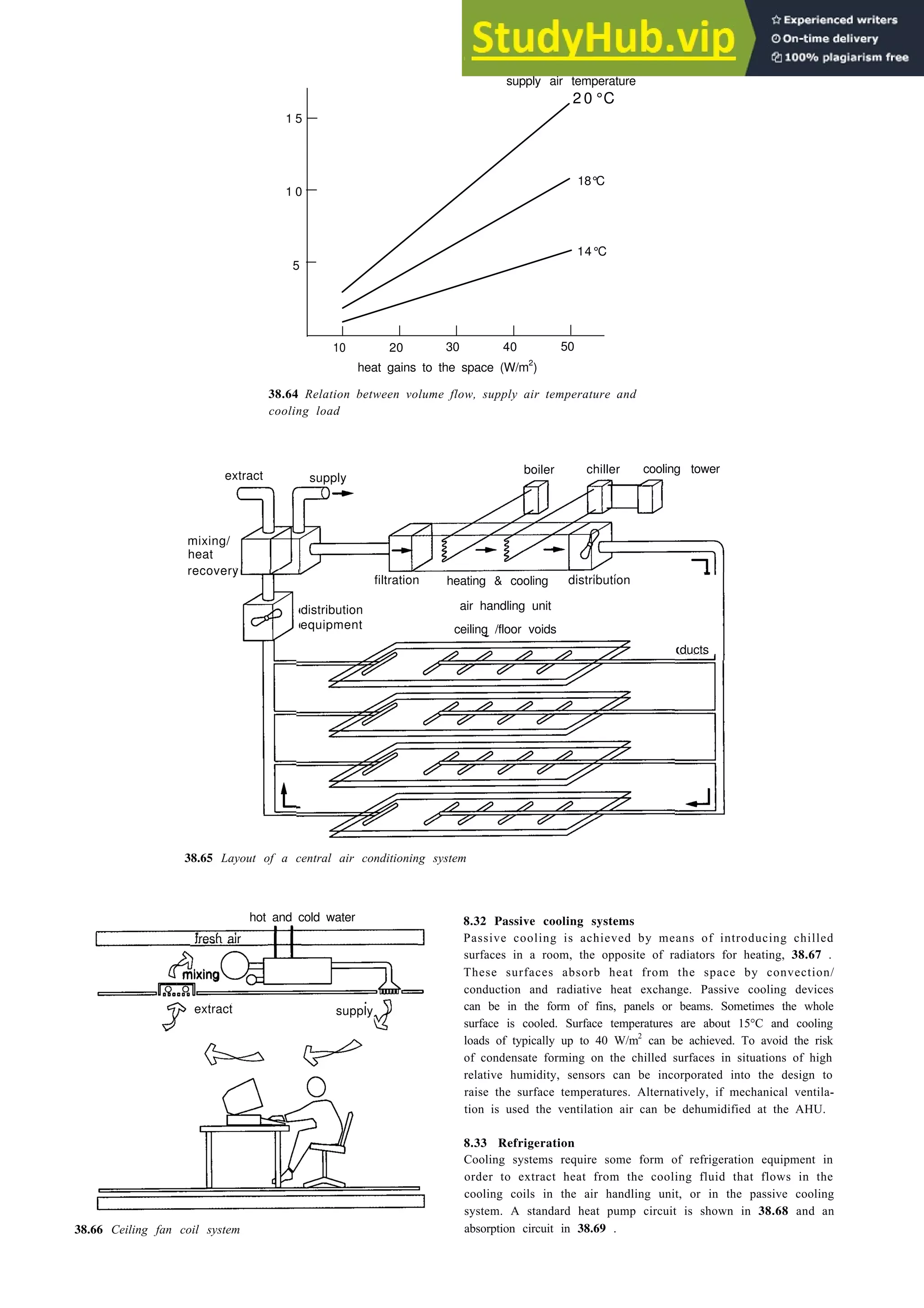
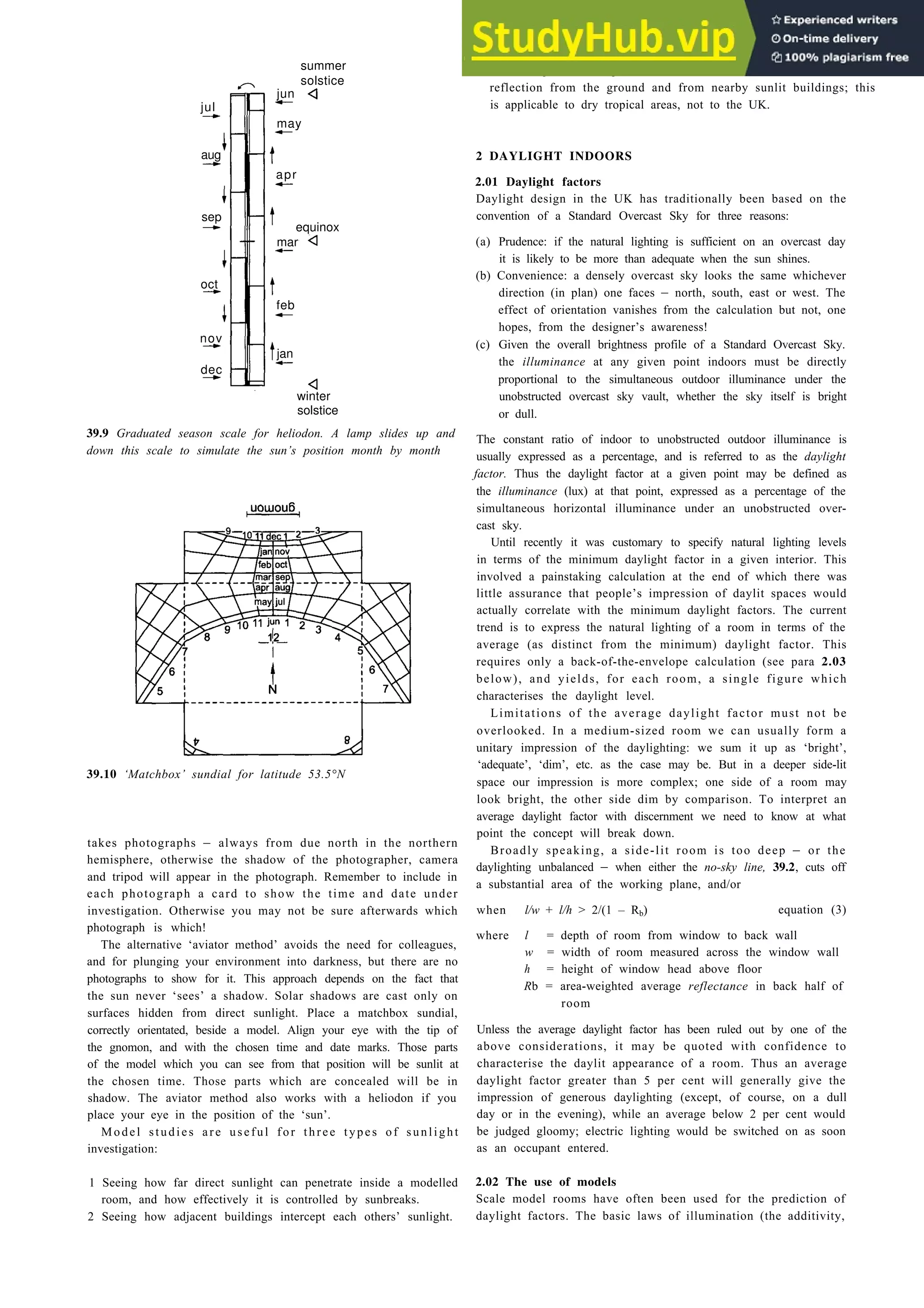
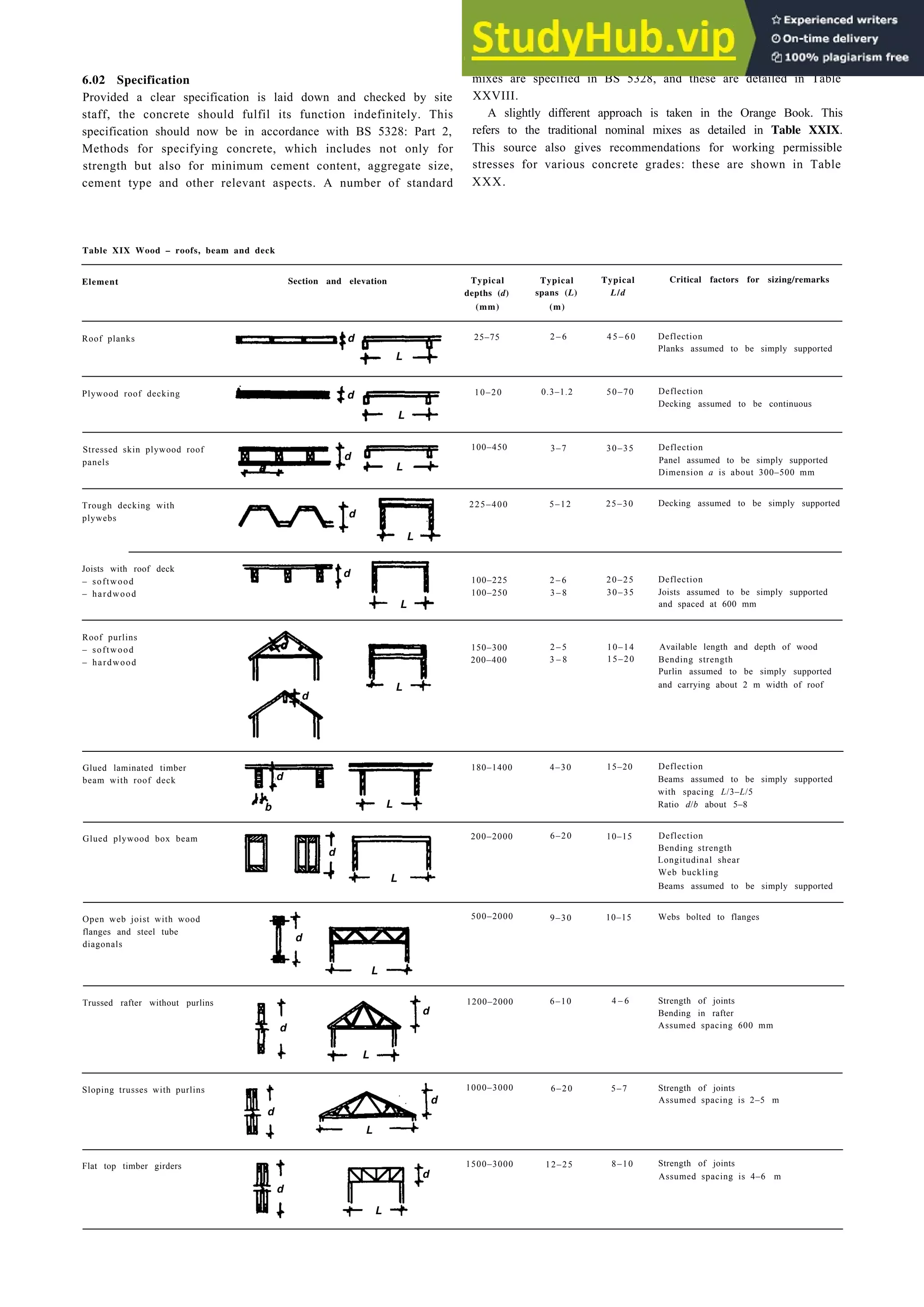
surface is the top of the keyboard) are available 30 mm lower.
Chairs for sitting workers are now by legislation required to
provide for vertical adjustment so that each individual can find the
right relationship with the worktop. However, it is important that
the feet remain in contact with the ground, and where this is not
possible, footrests should be provided.
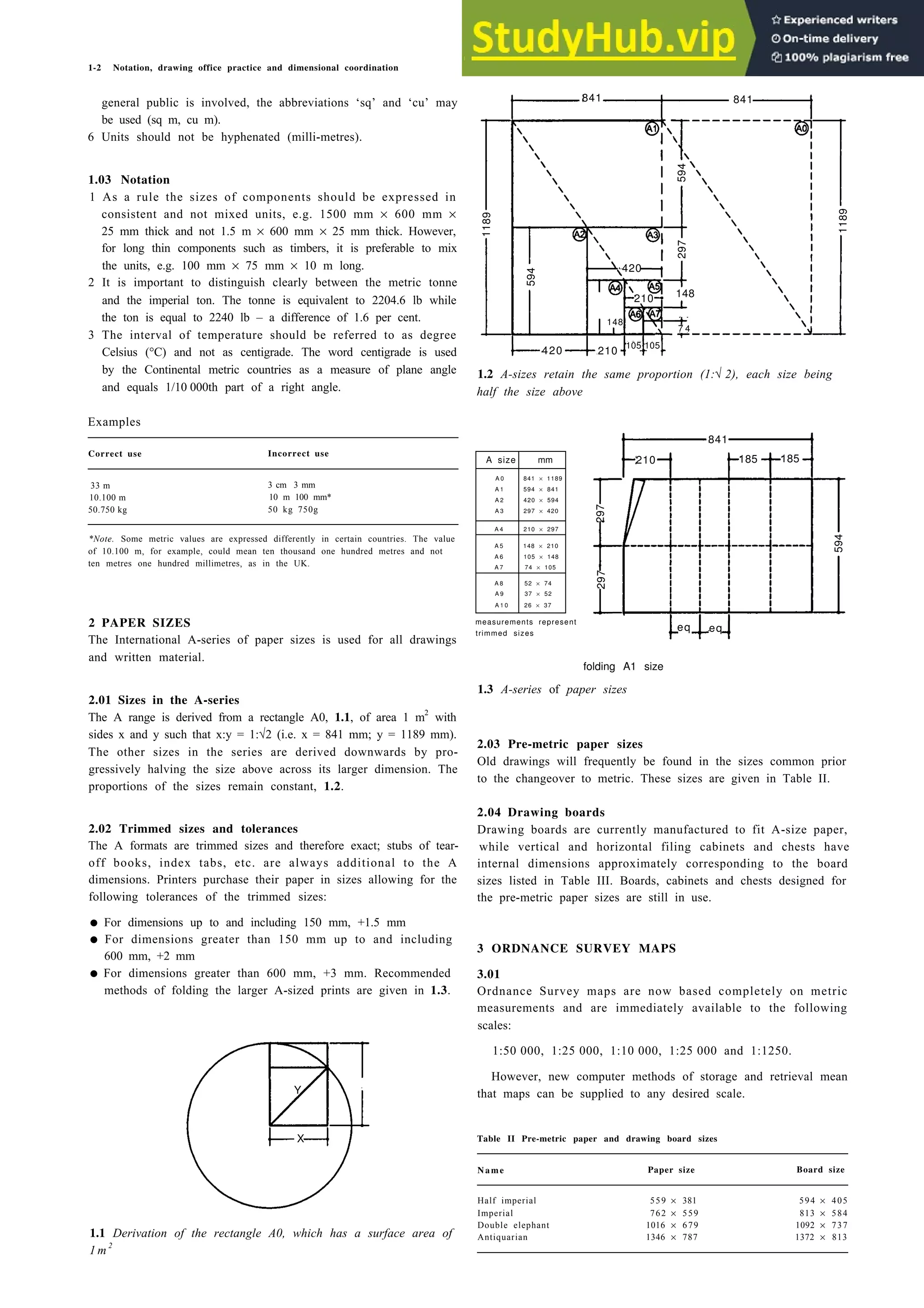
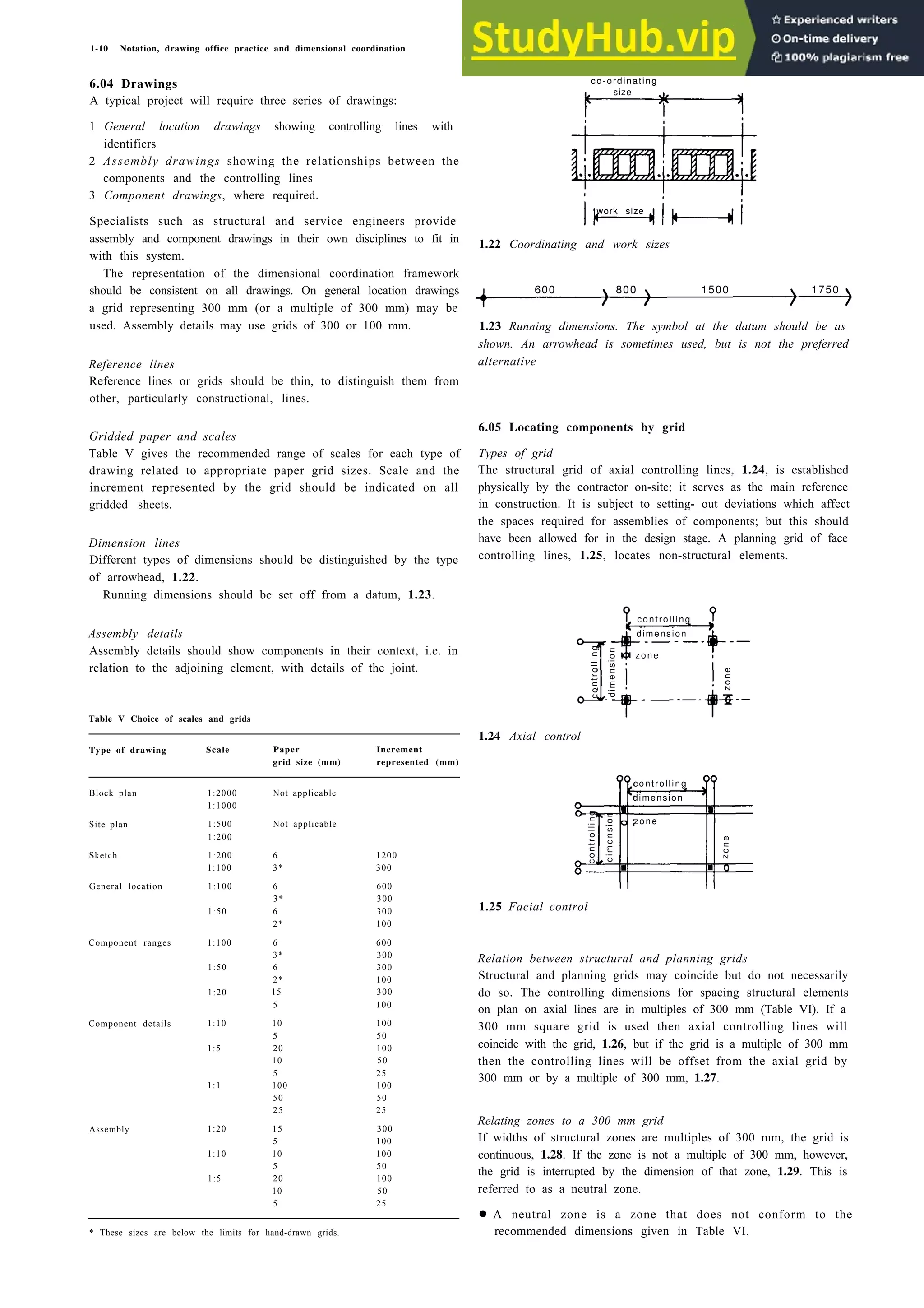
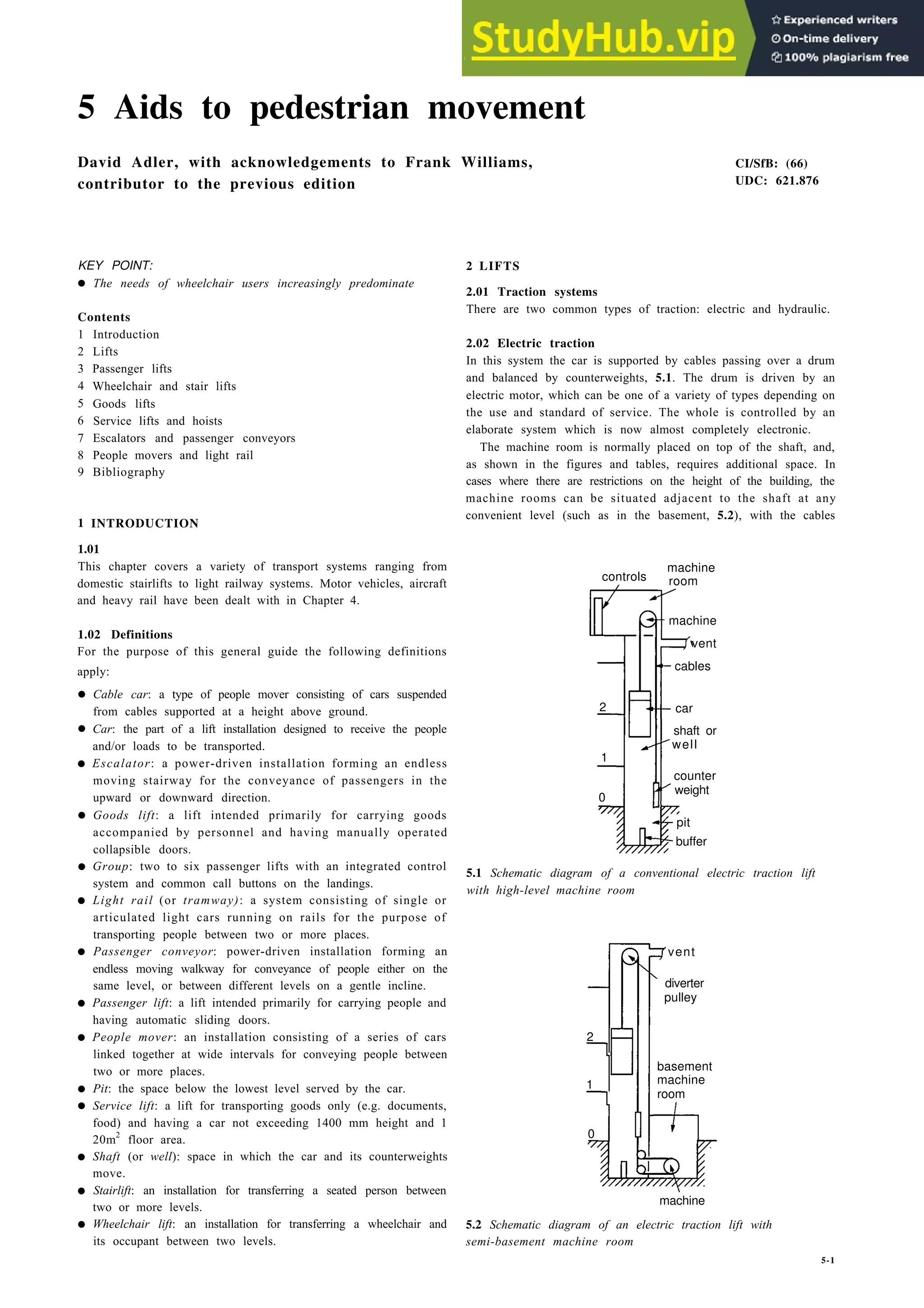
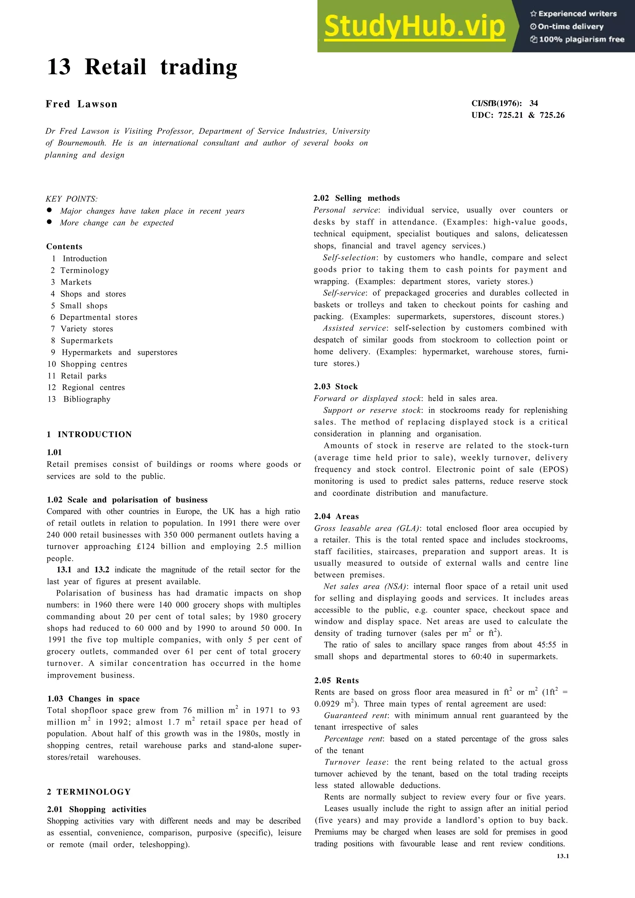
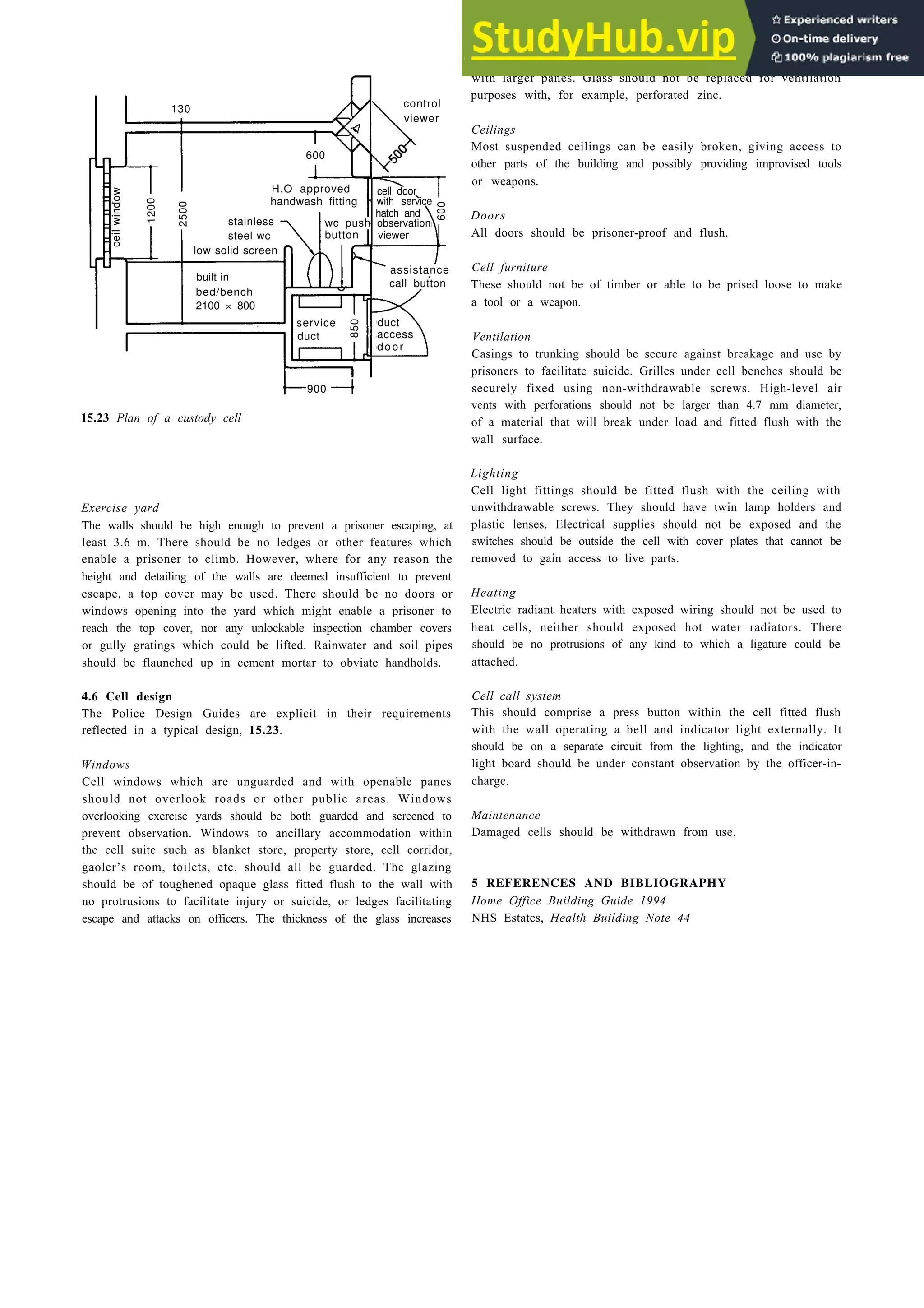
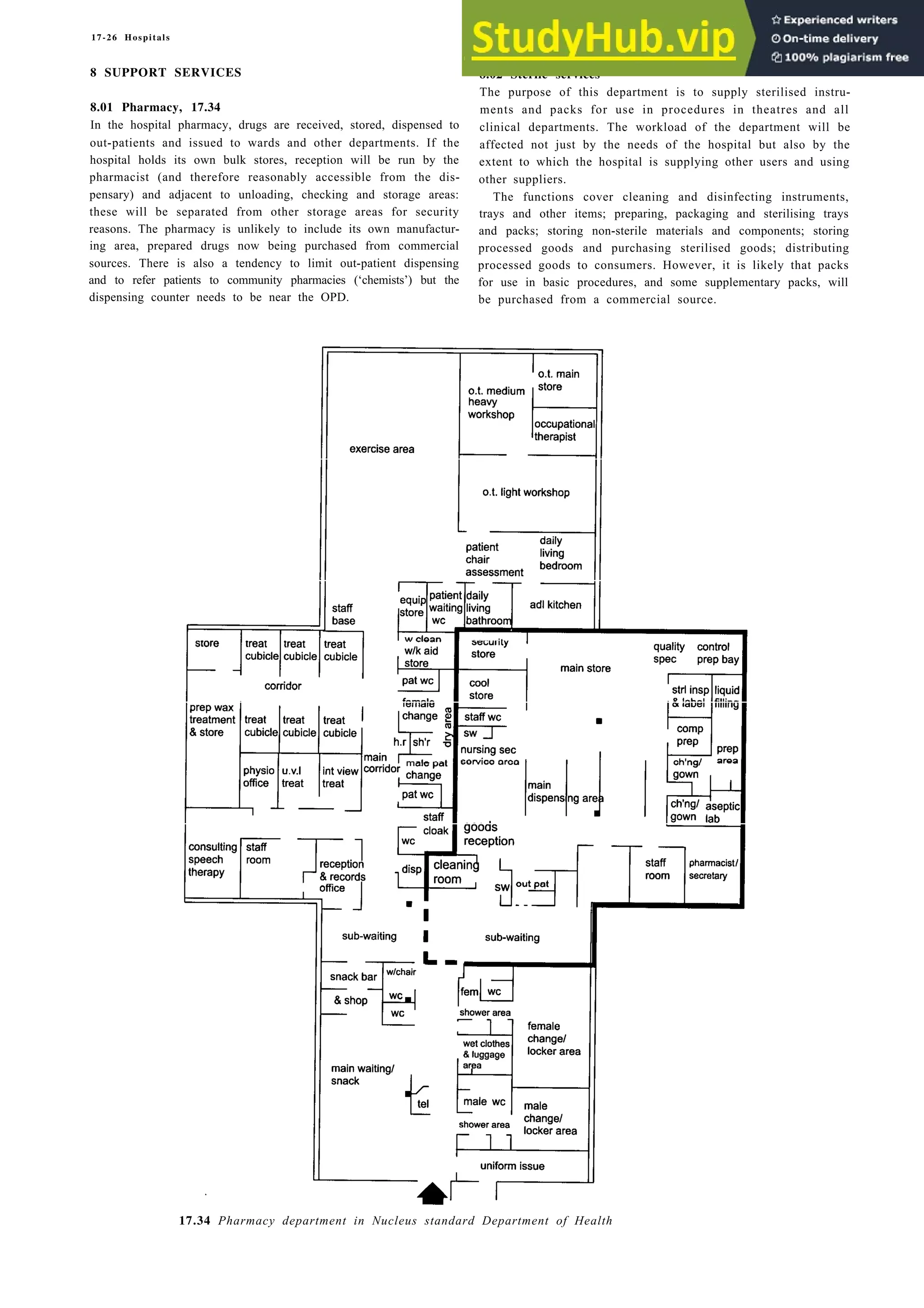
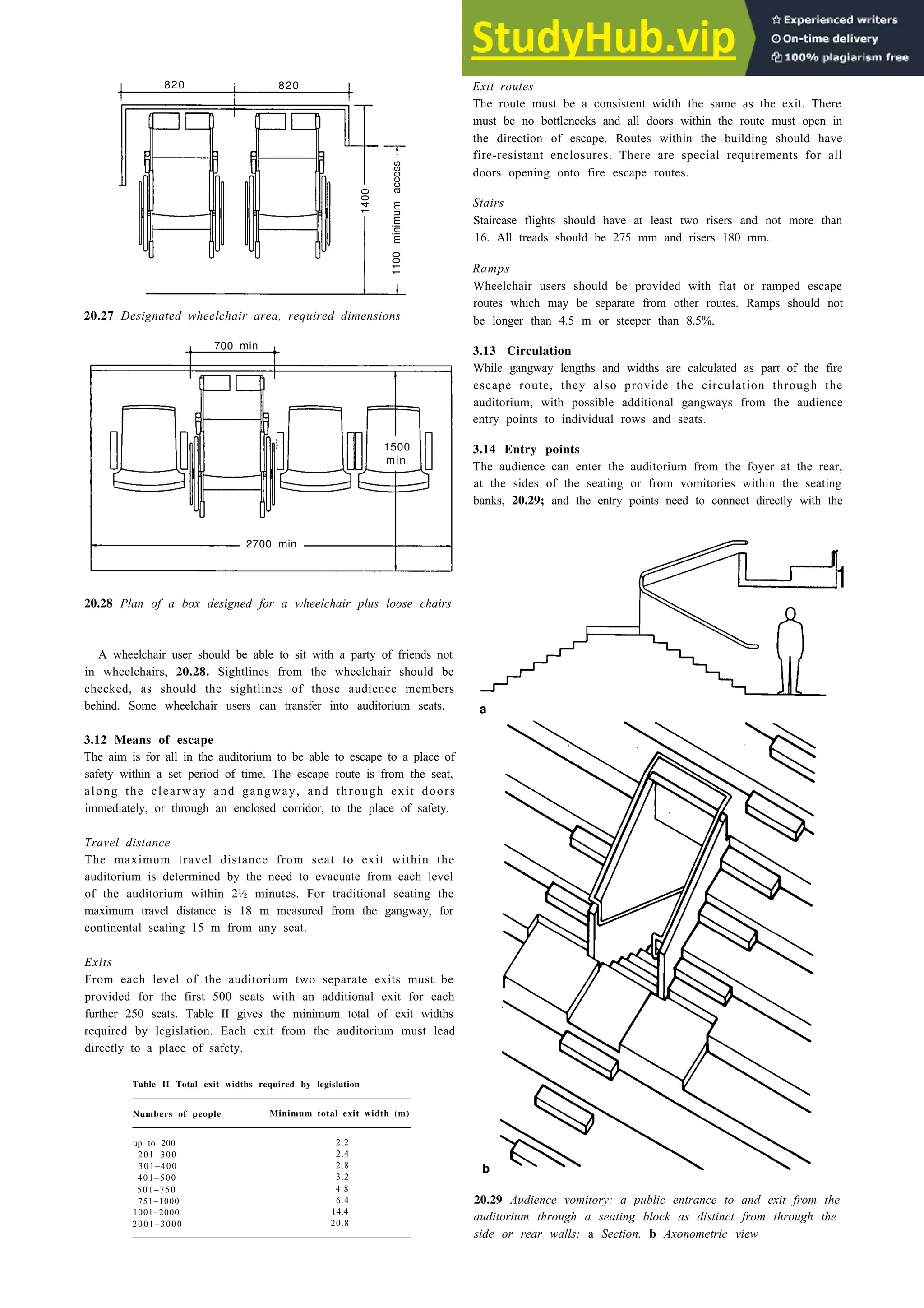
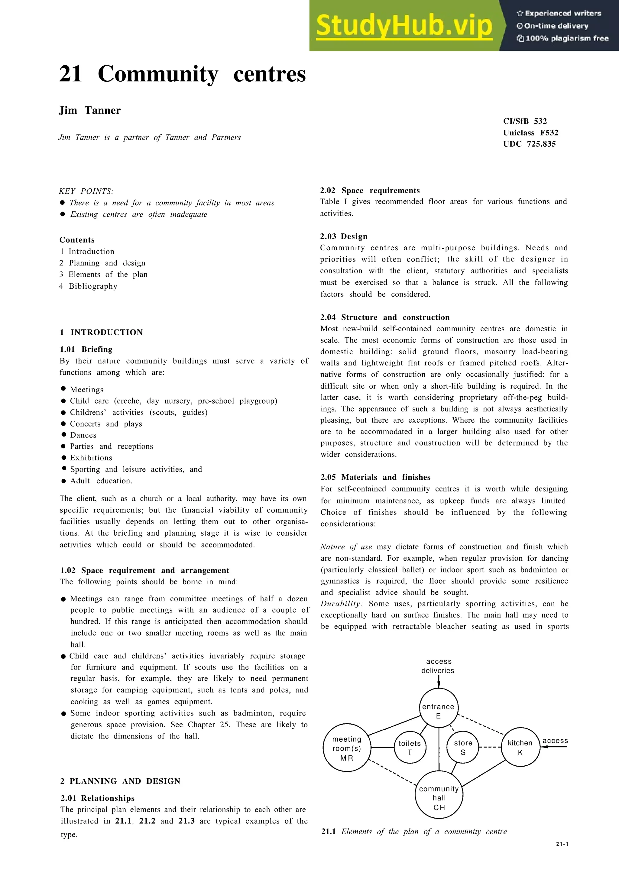
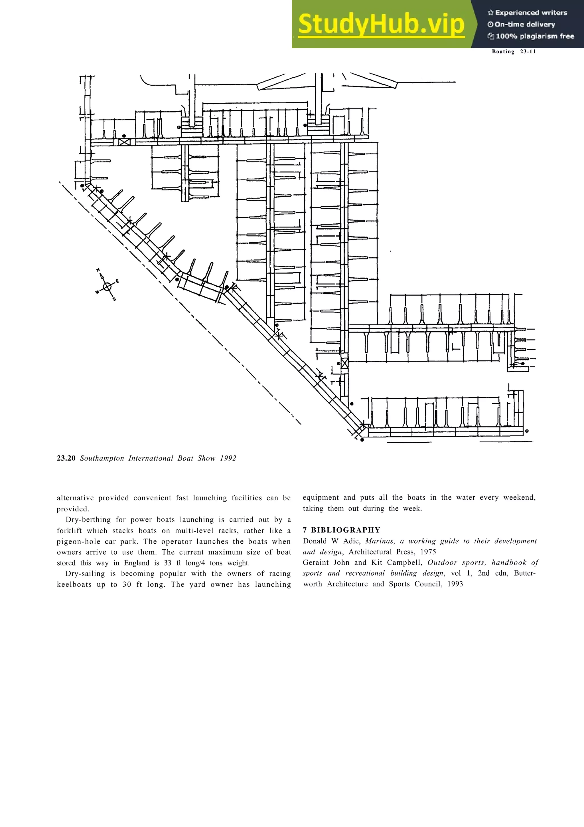
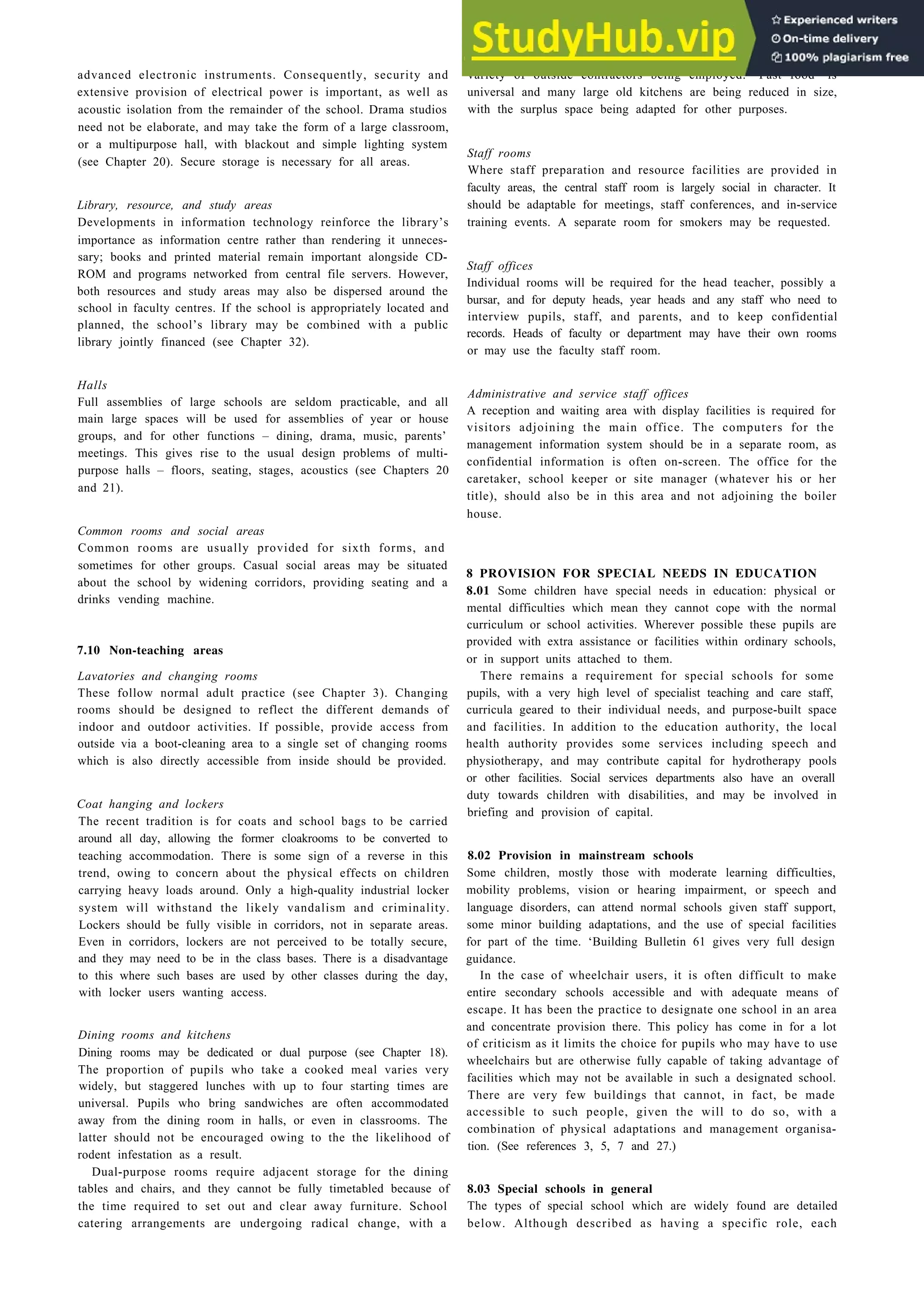
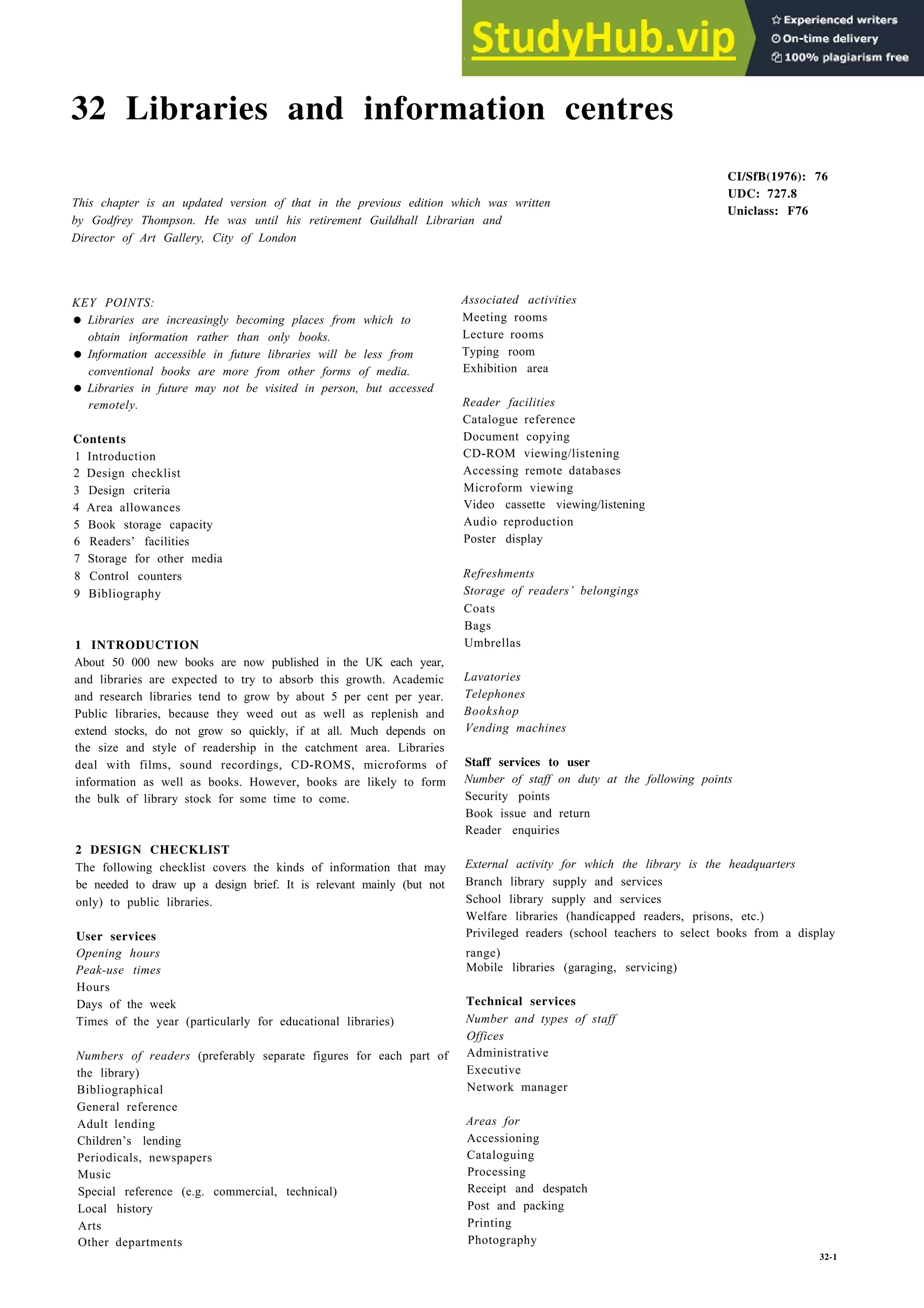
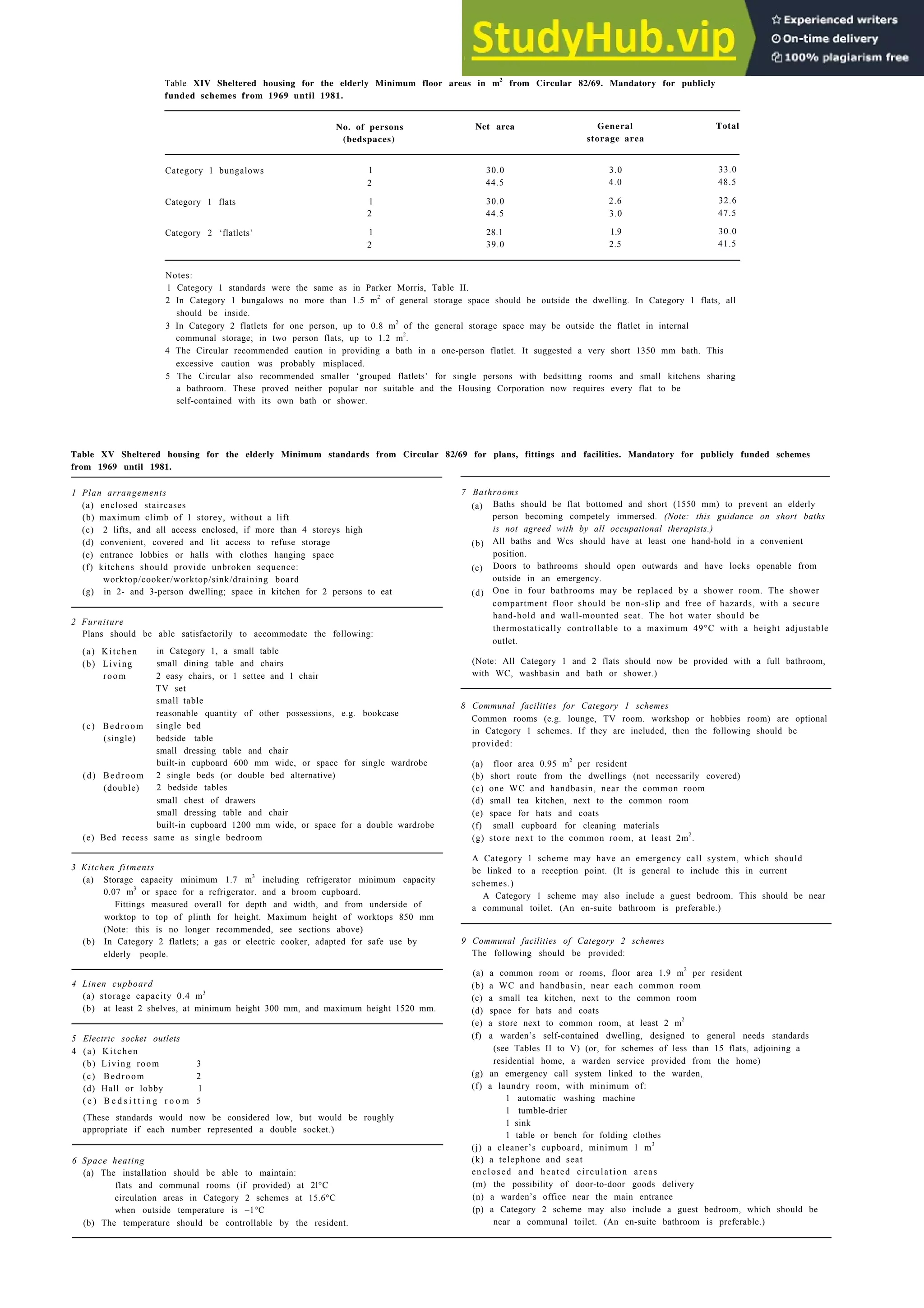
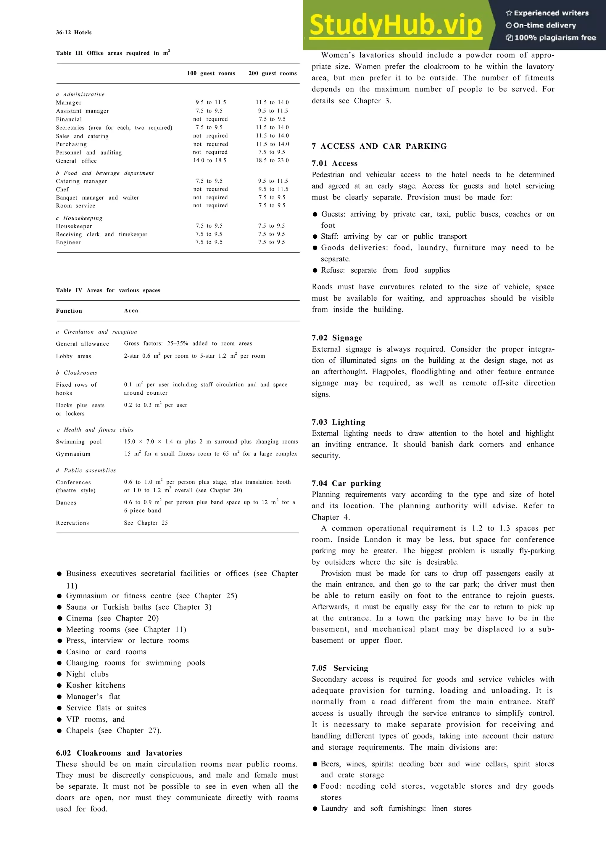
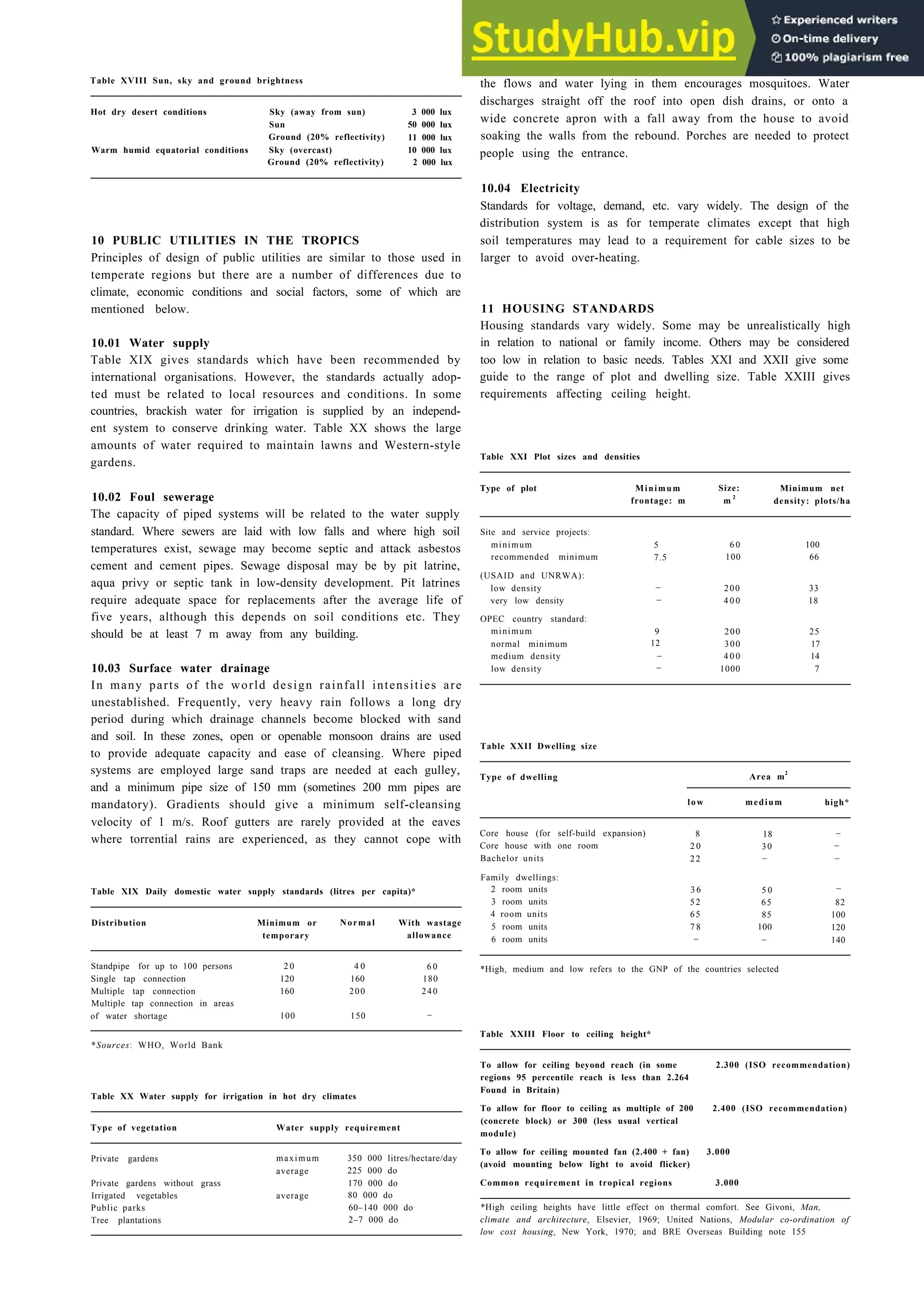
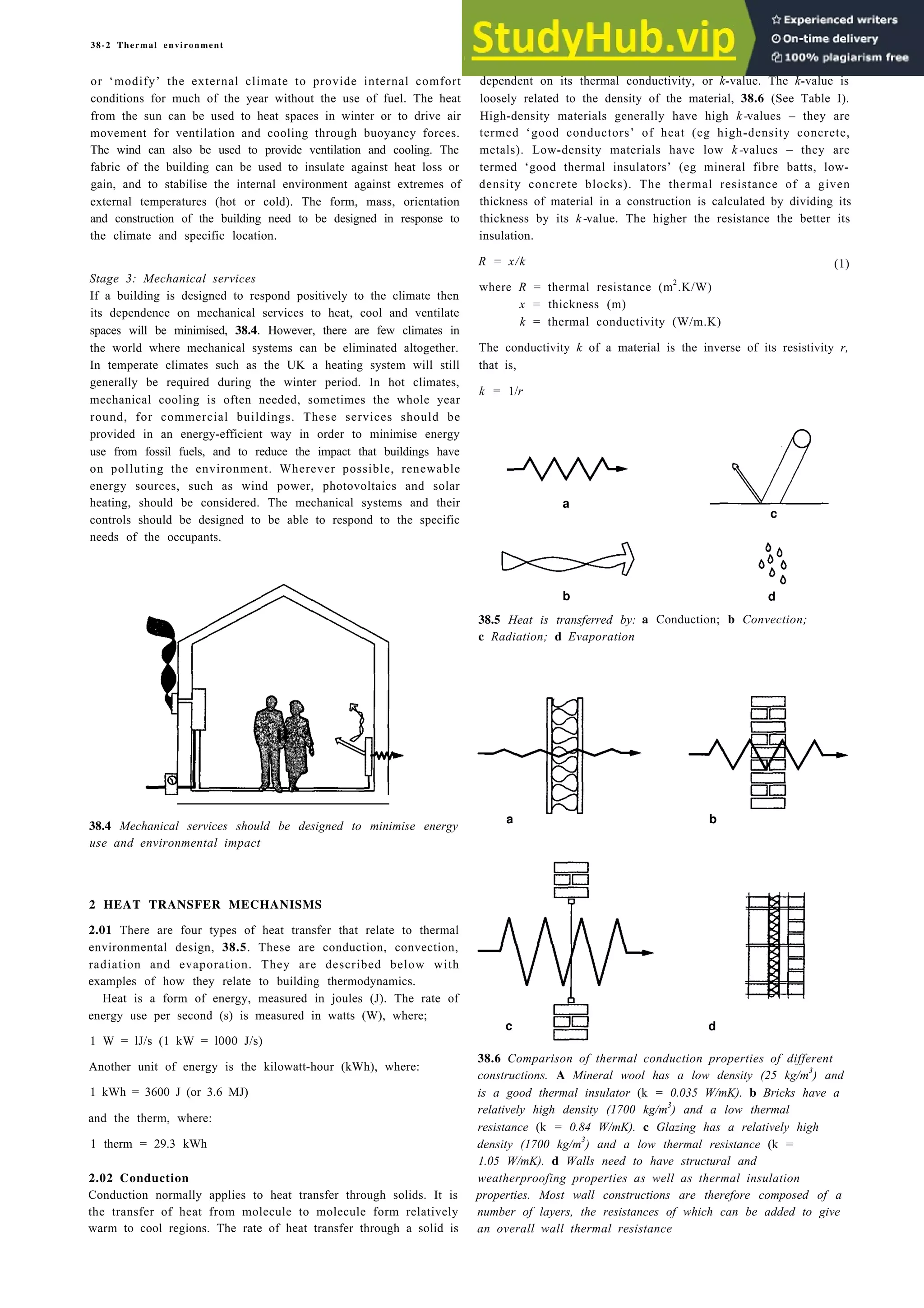
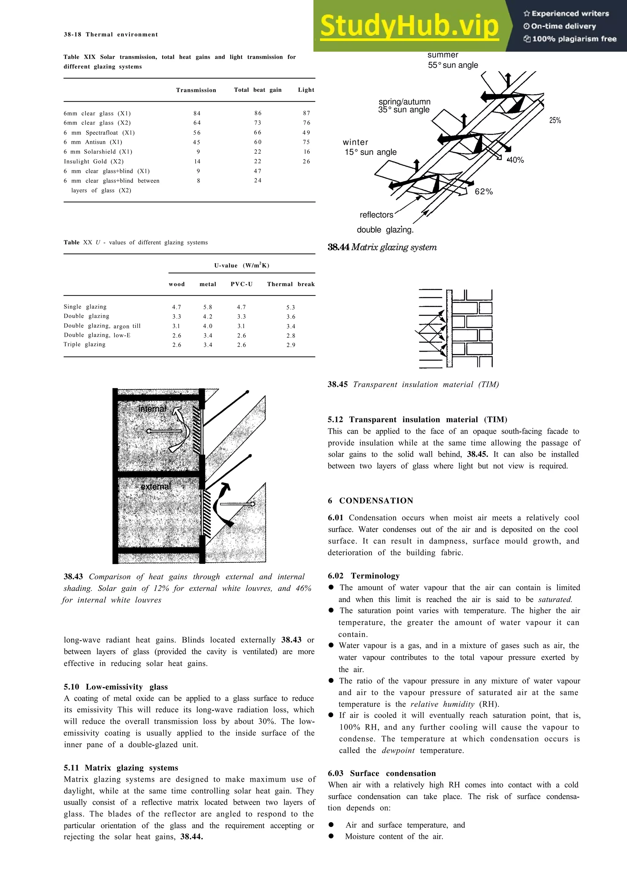
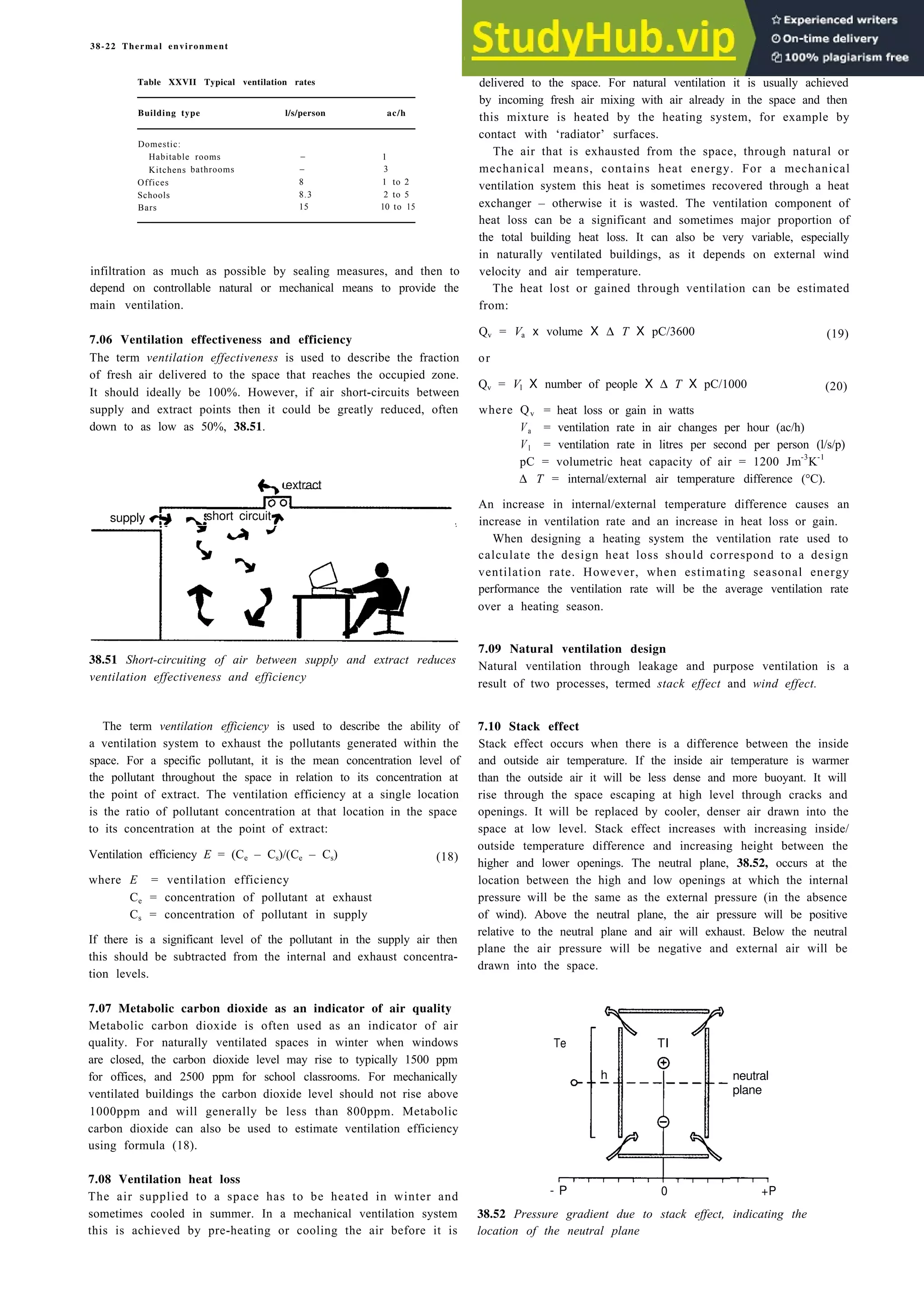
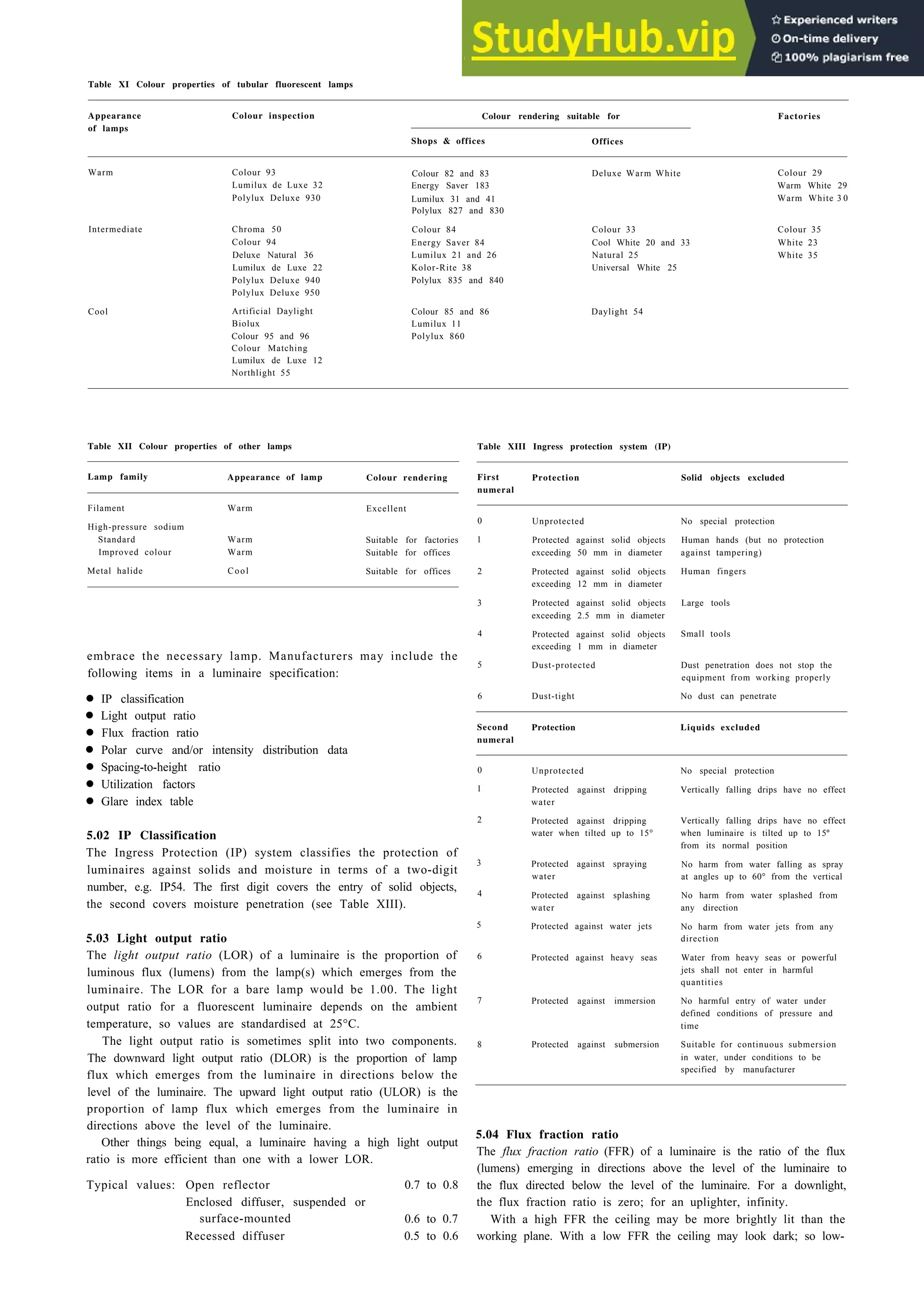
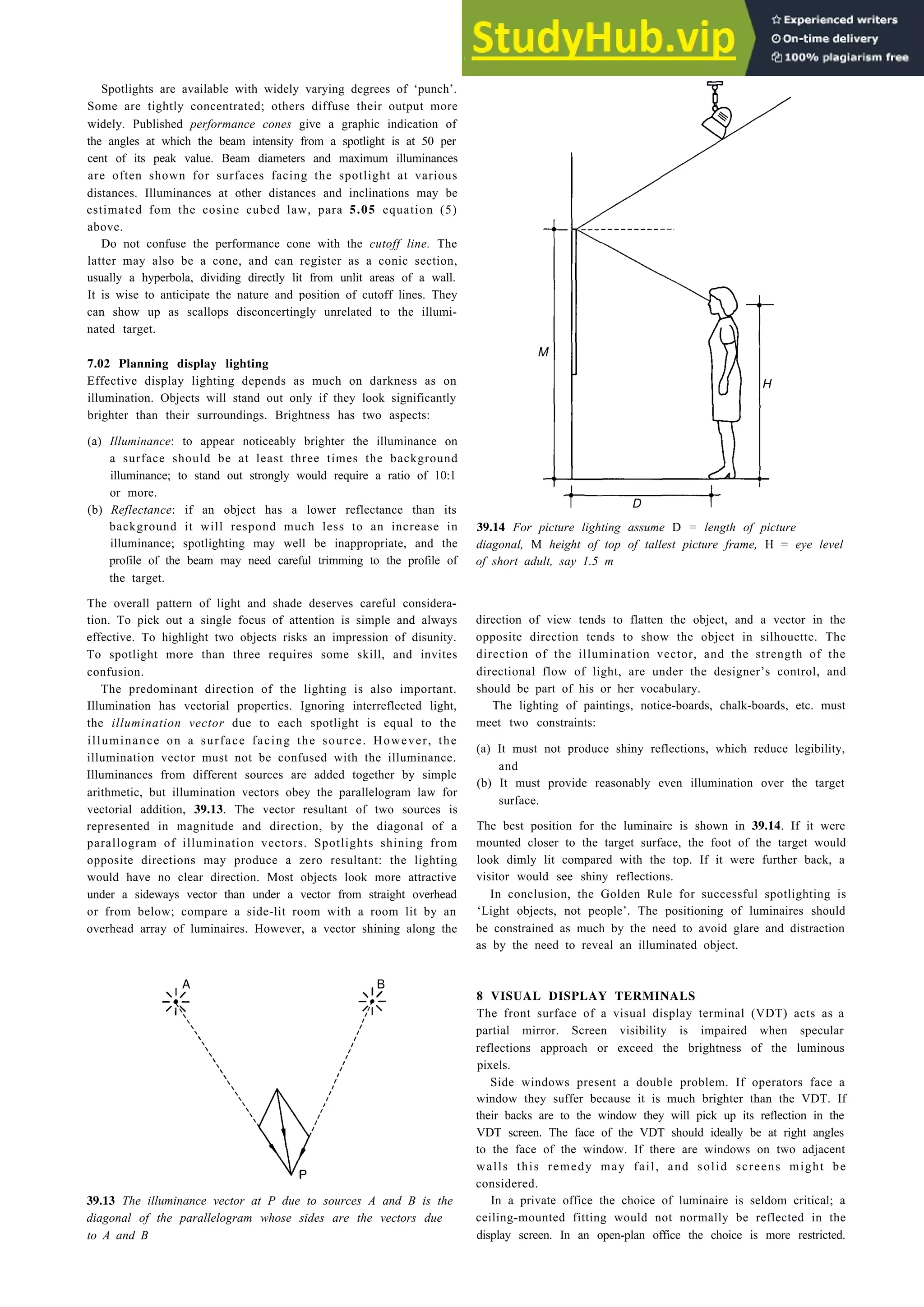
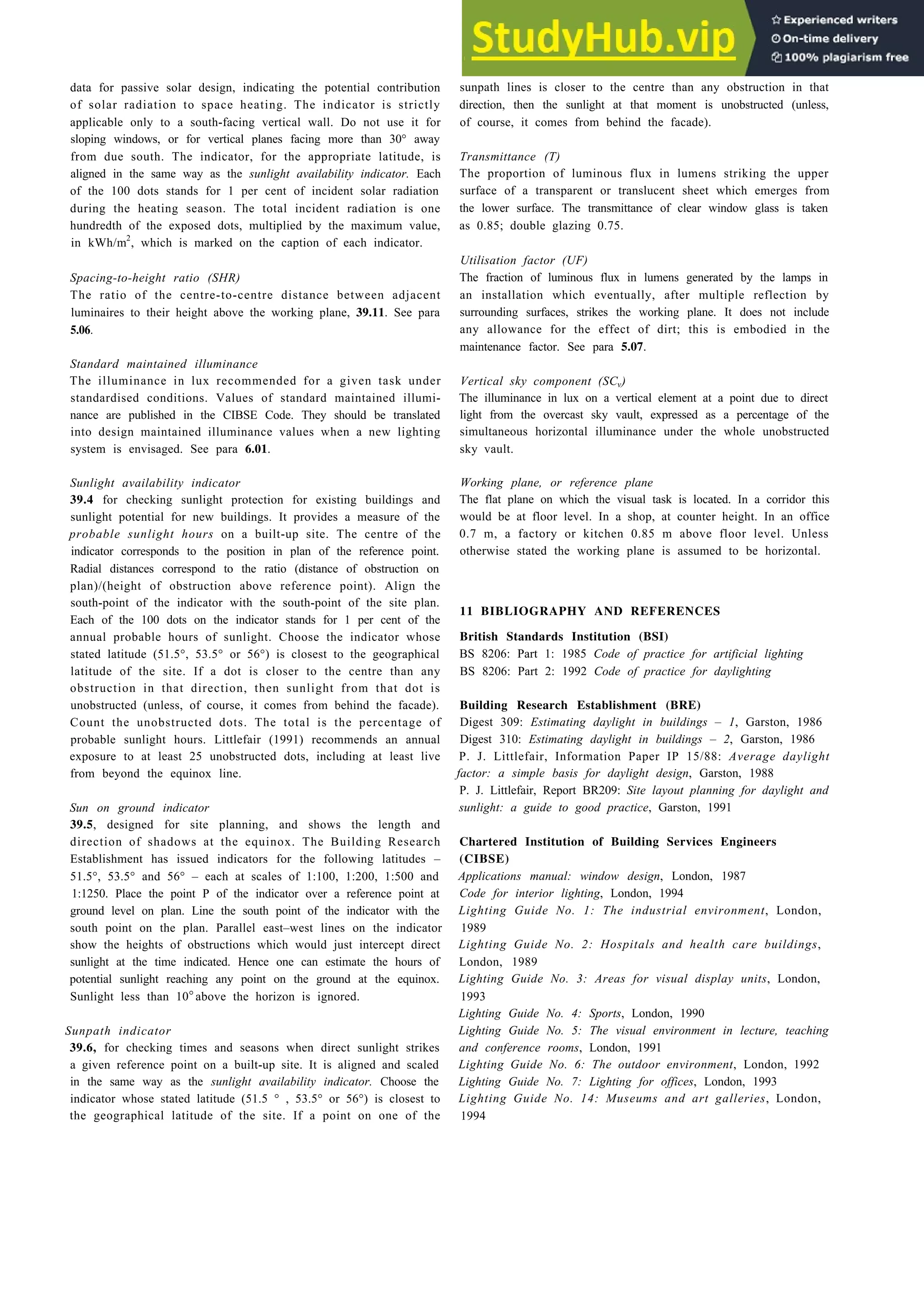
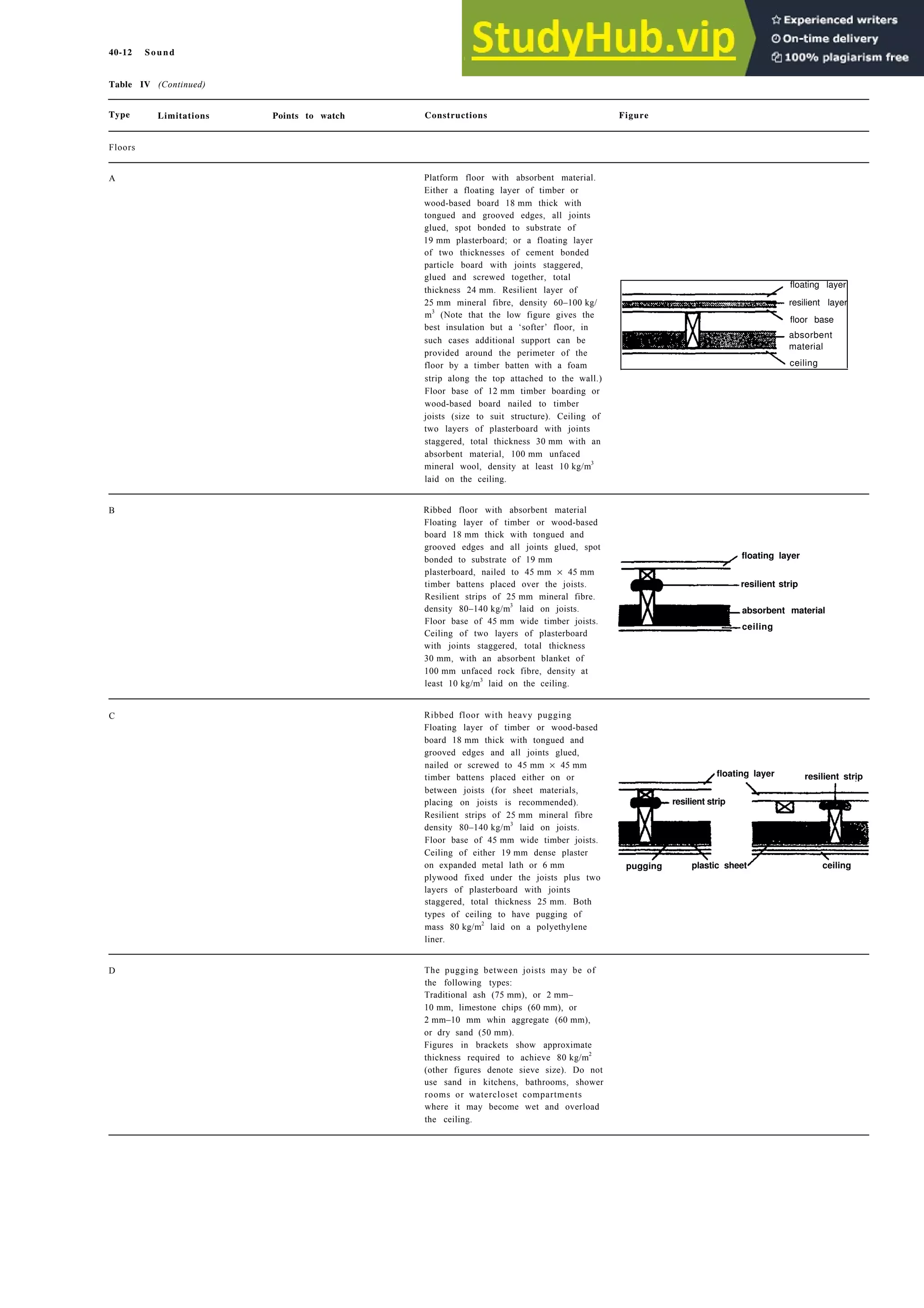
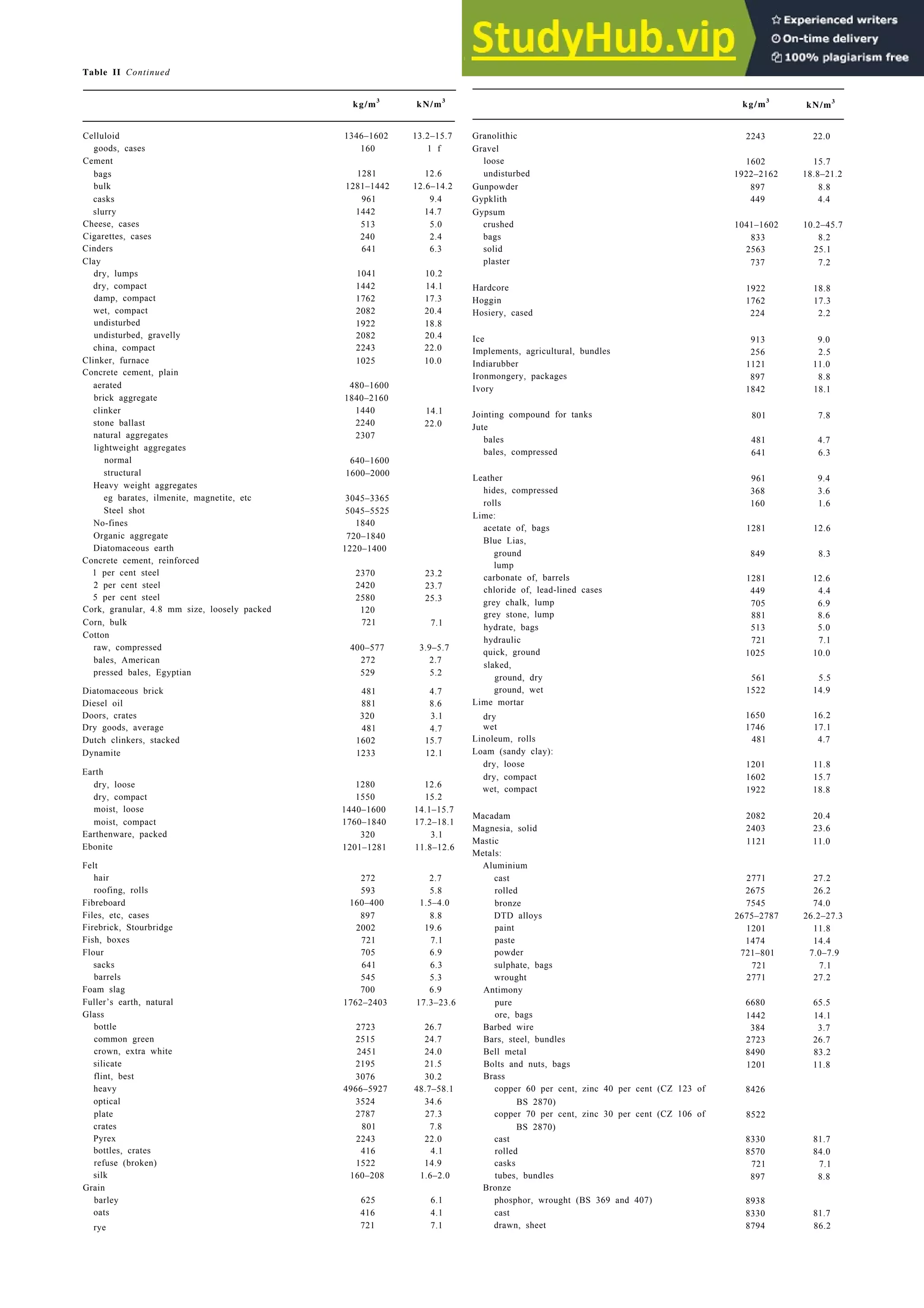
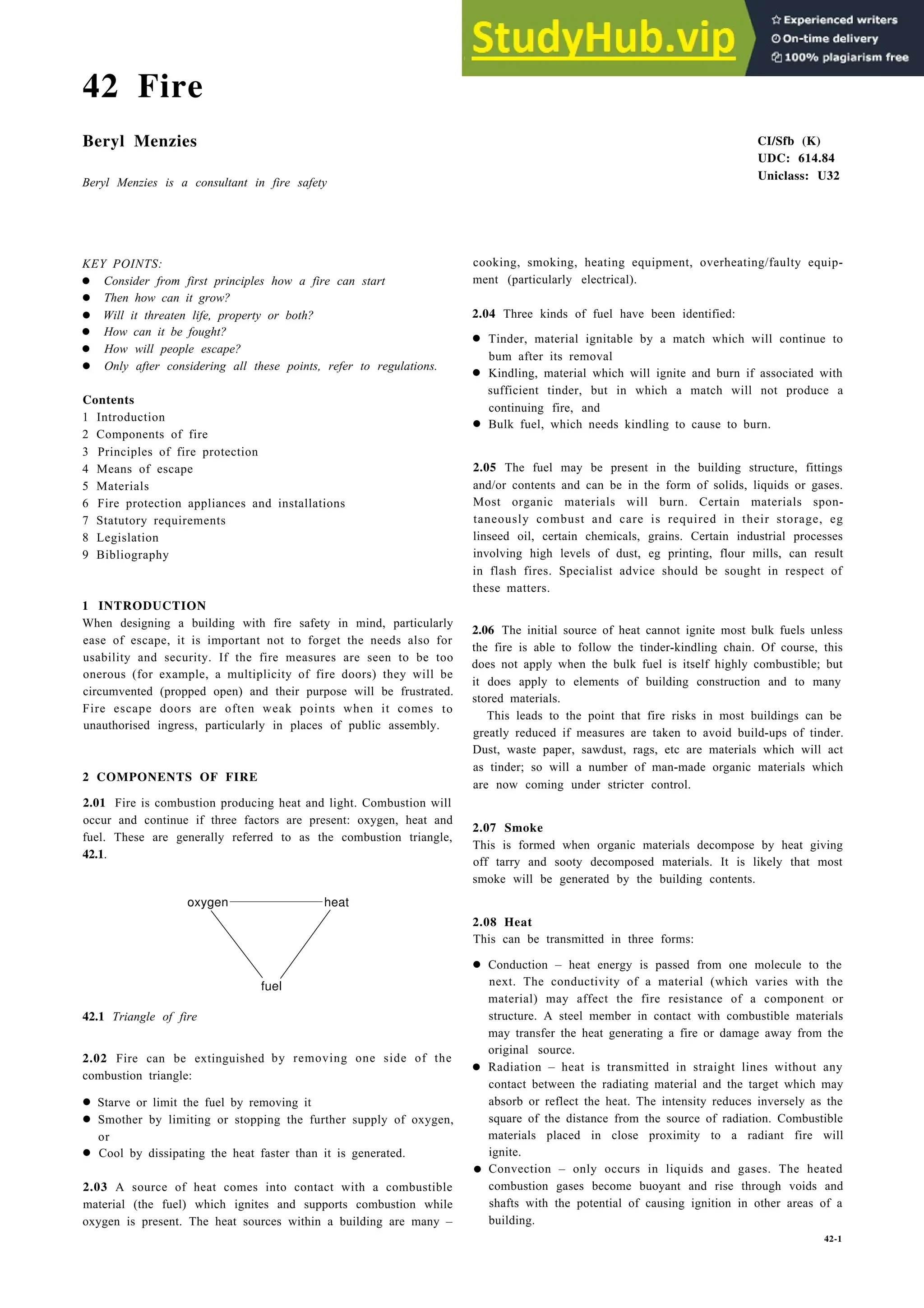
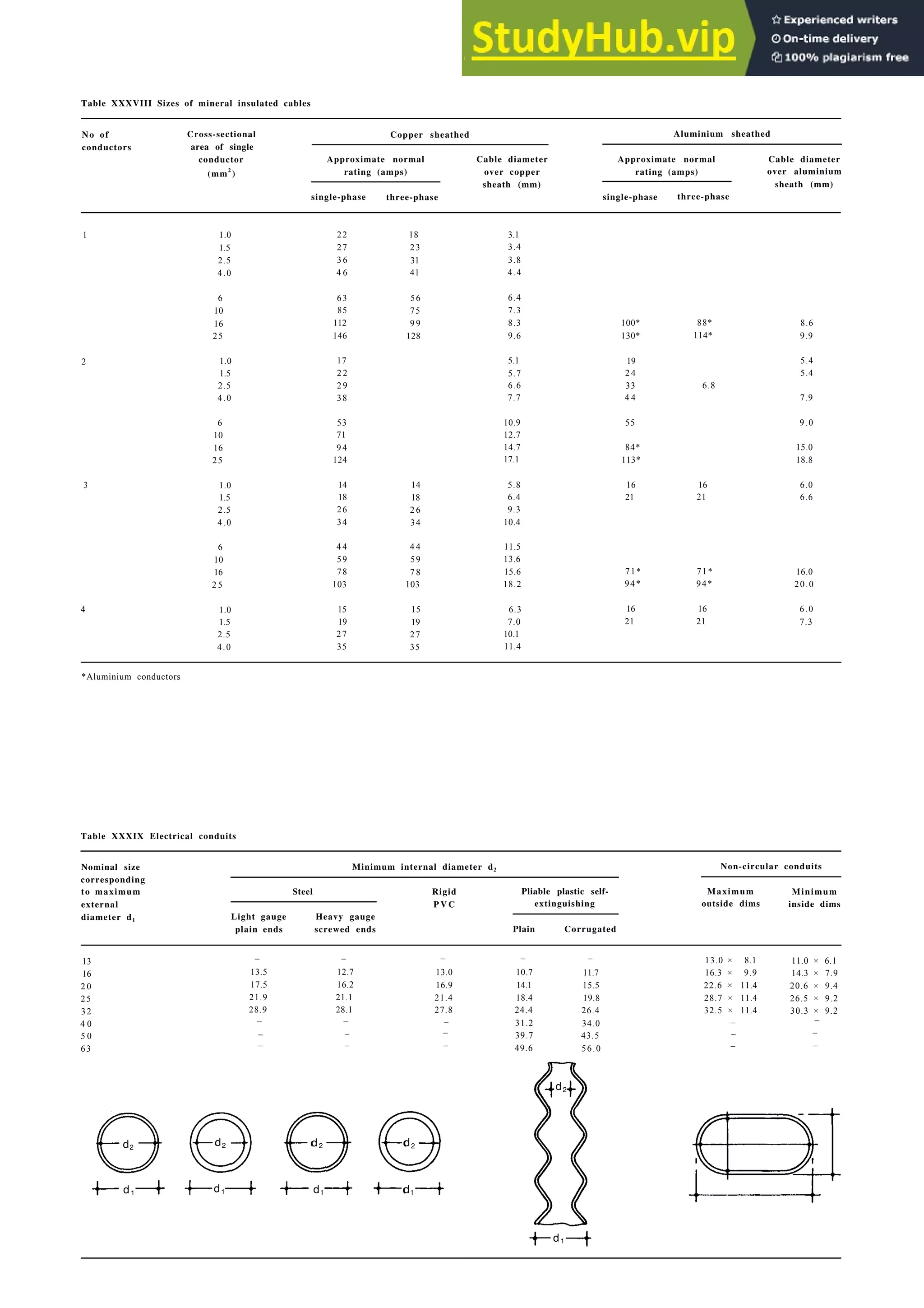
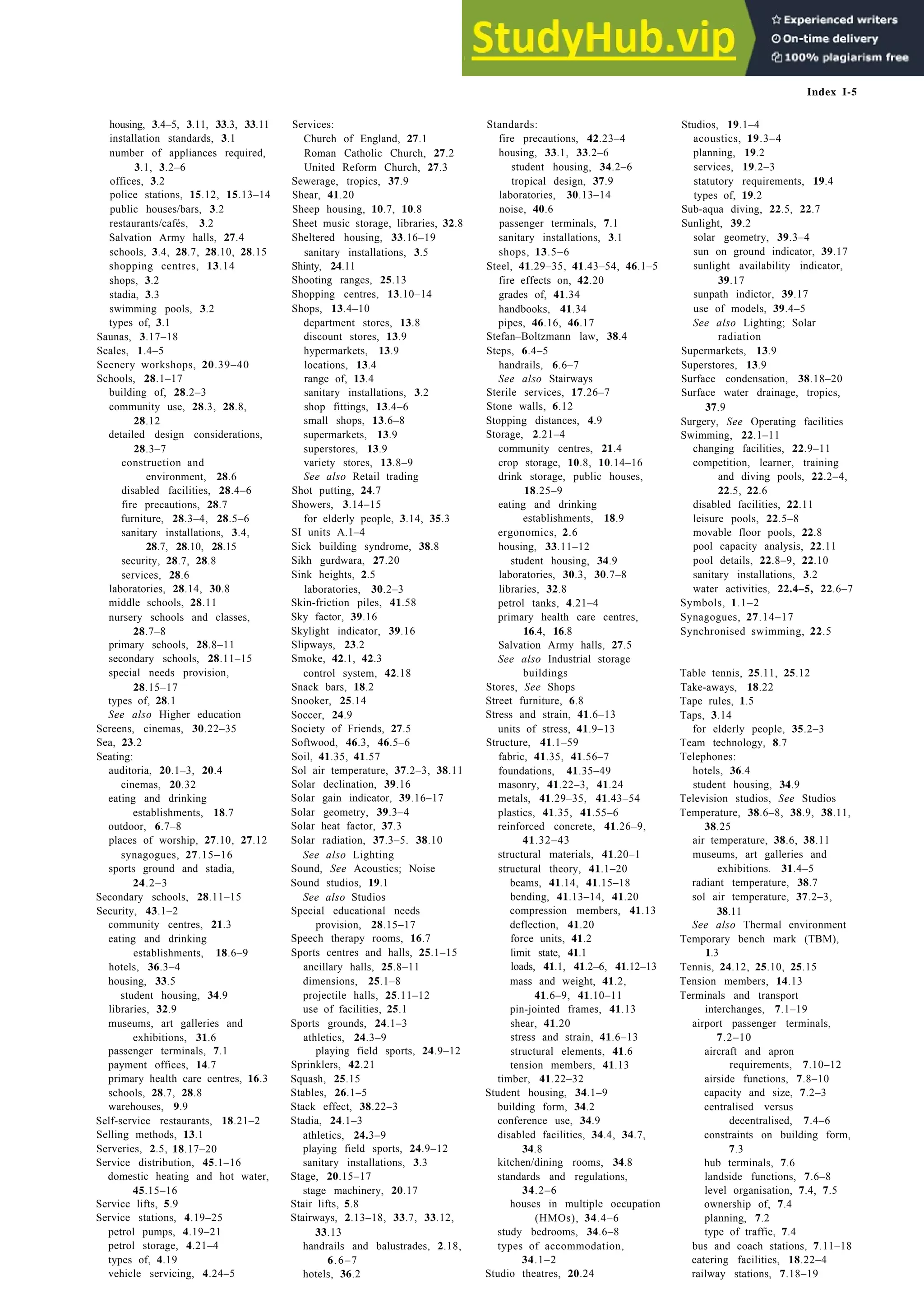
3.05 Computer work stations
Many office workers now work with visual display units (VDUs),
and these introduce further requirements for comfortable and
healthy working. People often find working at a screen tiring to the
eyes. 2.8 gives the recommended dimensions for minimising
fatigue; some people may need special spectacles. Most VDUs are
placed at or above eye level so that normal bifocals do not help.
Opticians are now used to supplying ‘intermediate’ spectacles with
the normal bifocal facility for viewing the keyboard and material
on the desk, with the upper part allowing focus on the near
distance. This permits the VDU to be placed between 900 to
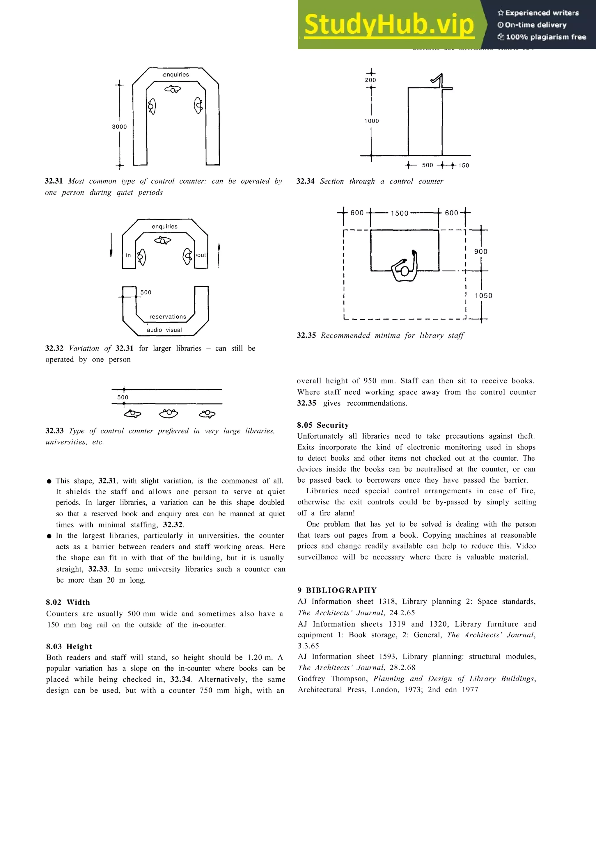
1000 mm distant from the user.
accessibility
50%
accessibility
83%
inaccessible
not easily accessible
accessible
easily accessible
fixed
shelves
2.9 Accessibility of storage:
a Zones of accessibility.
adjustable wall
unit shelves
pull-out base
unit shelves
b Frequently needed
articles.
c Less frequently needed
articles higher
d Less frequently needed
articles lower
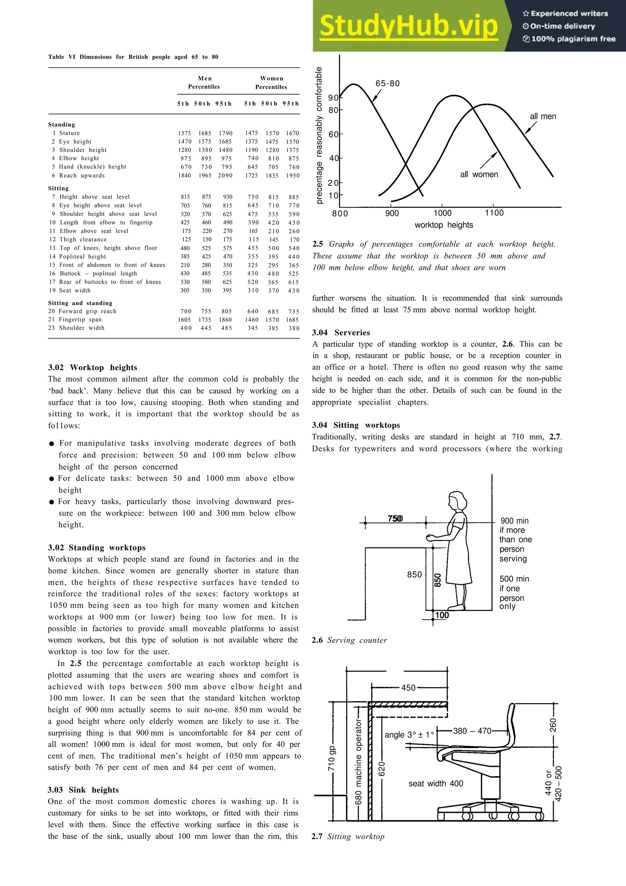
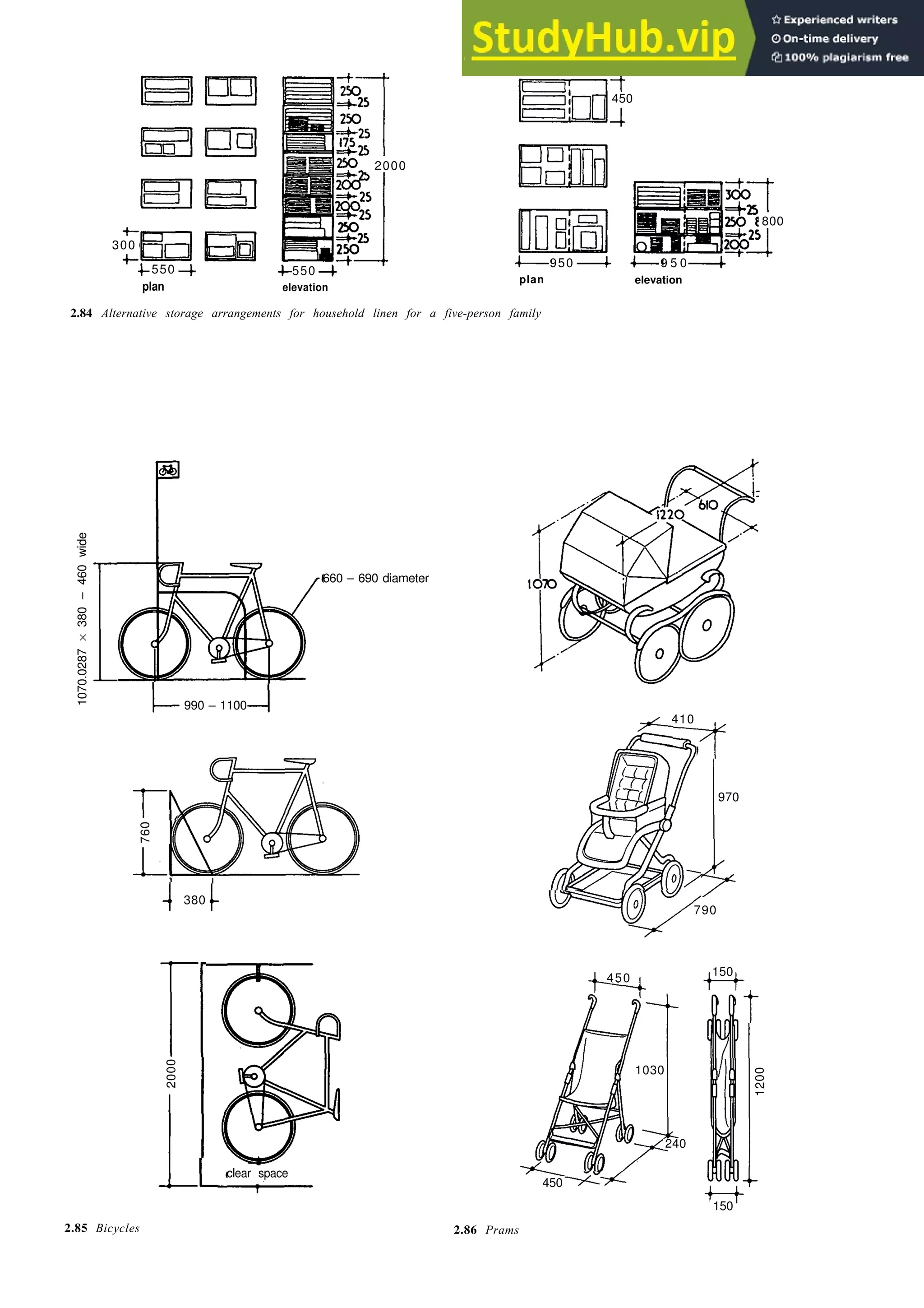
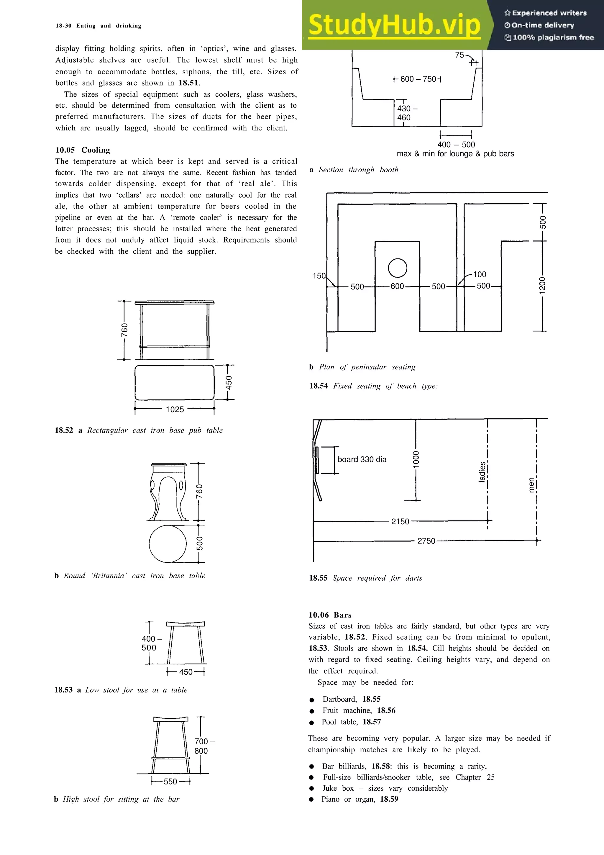
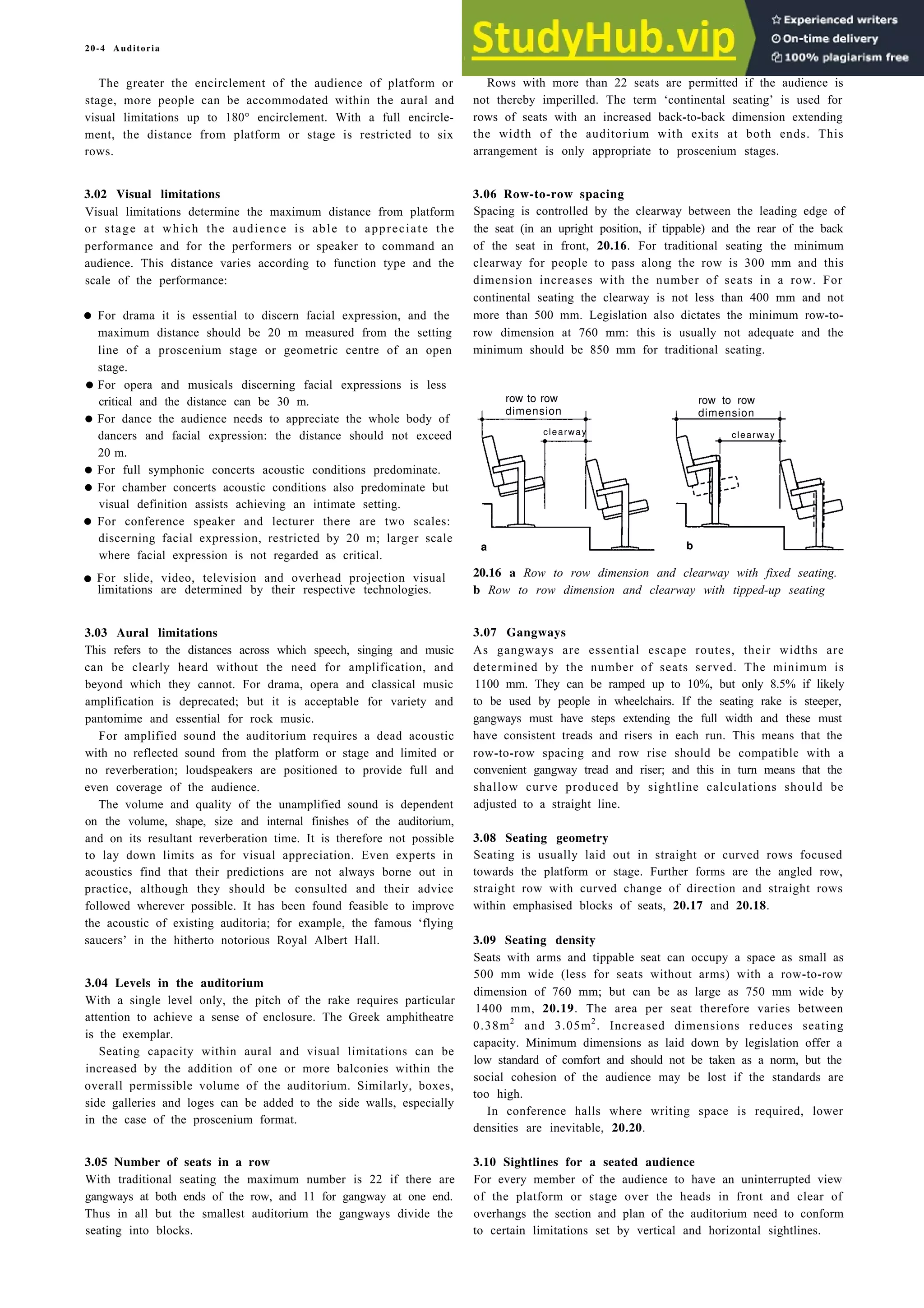
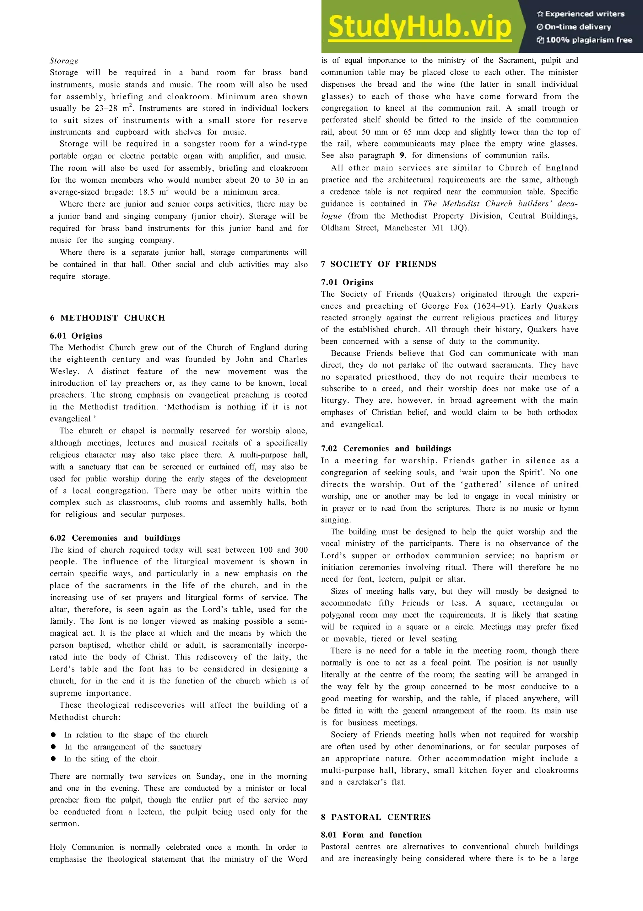
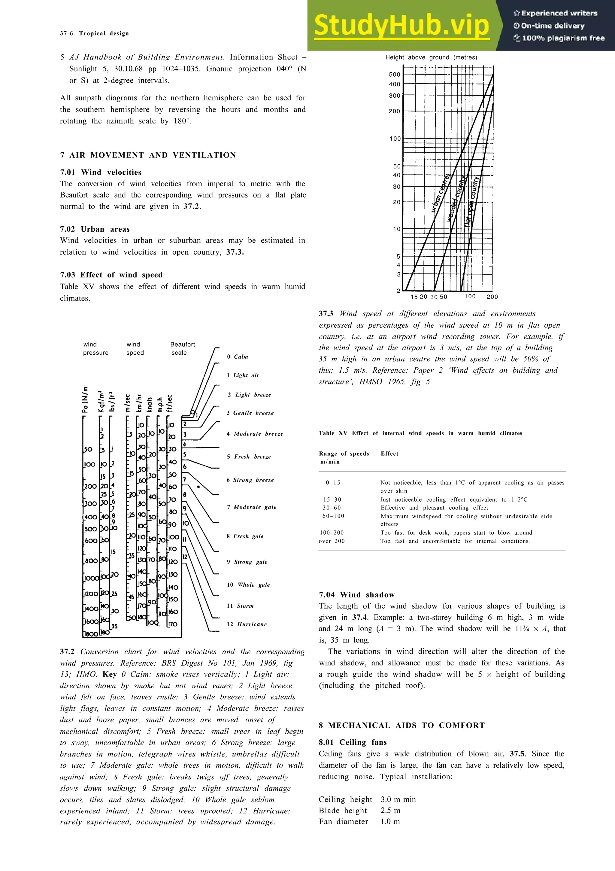
3.06 Storage
Two of the commonest operations at work and in the home is the
stowage and retrieval of items into and from storage. 2.9 shows the
recommended heights for various storage areas for general use;
2.10 gives particular requirements where elderly people are
concerned.
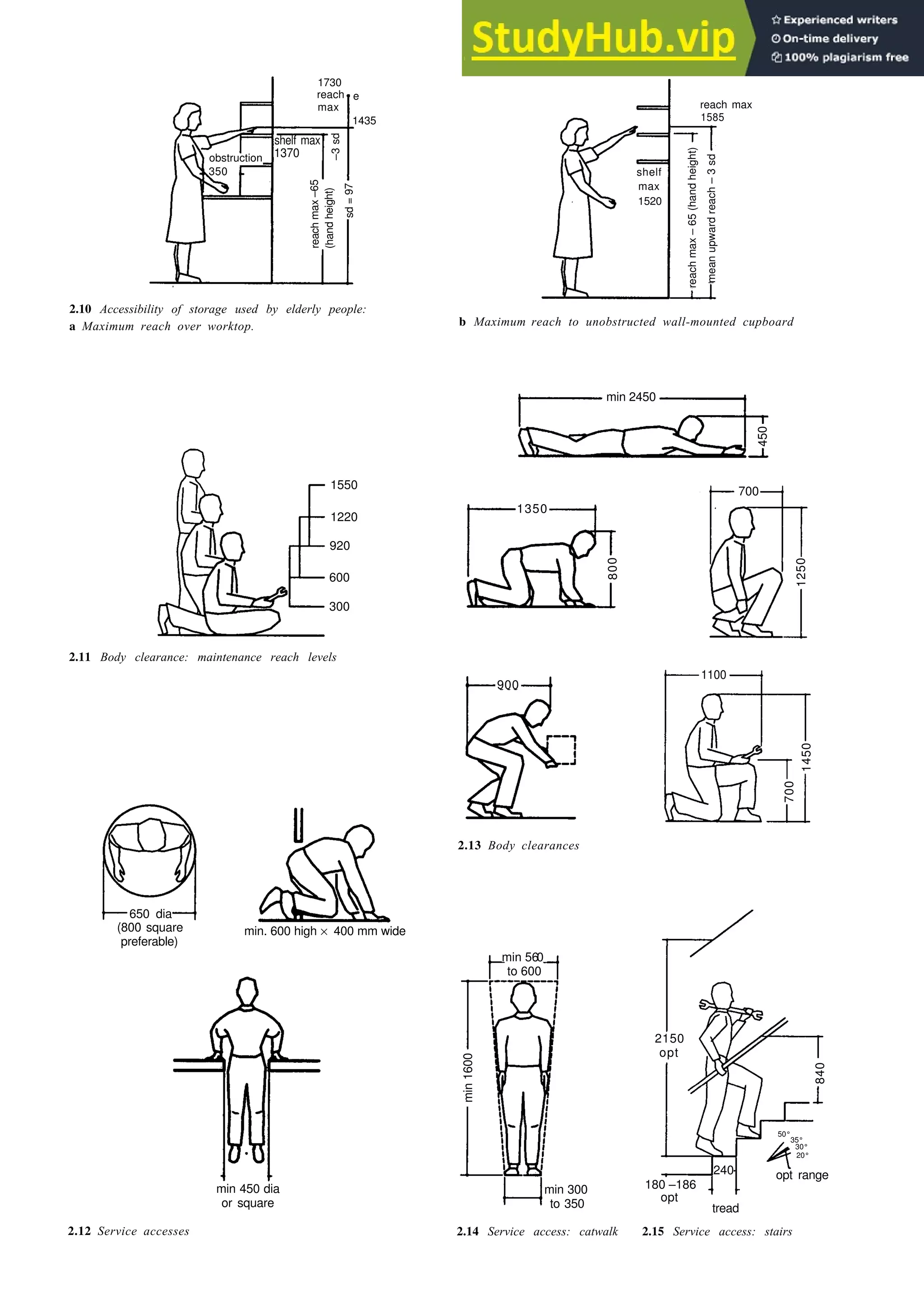
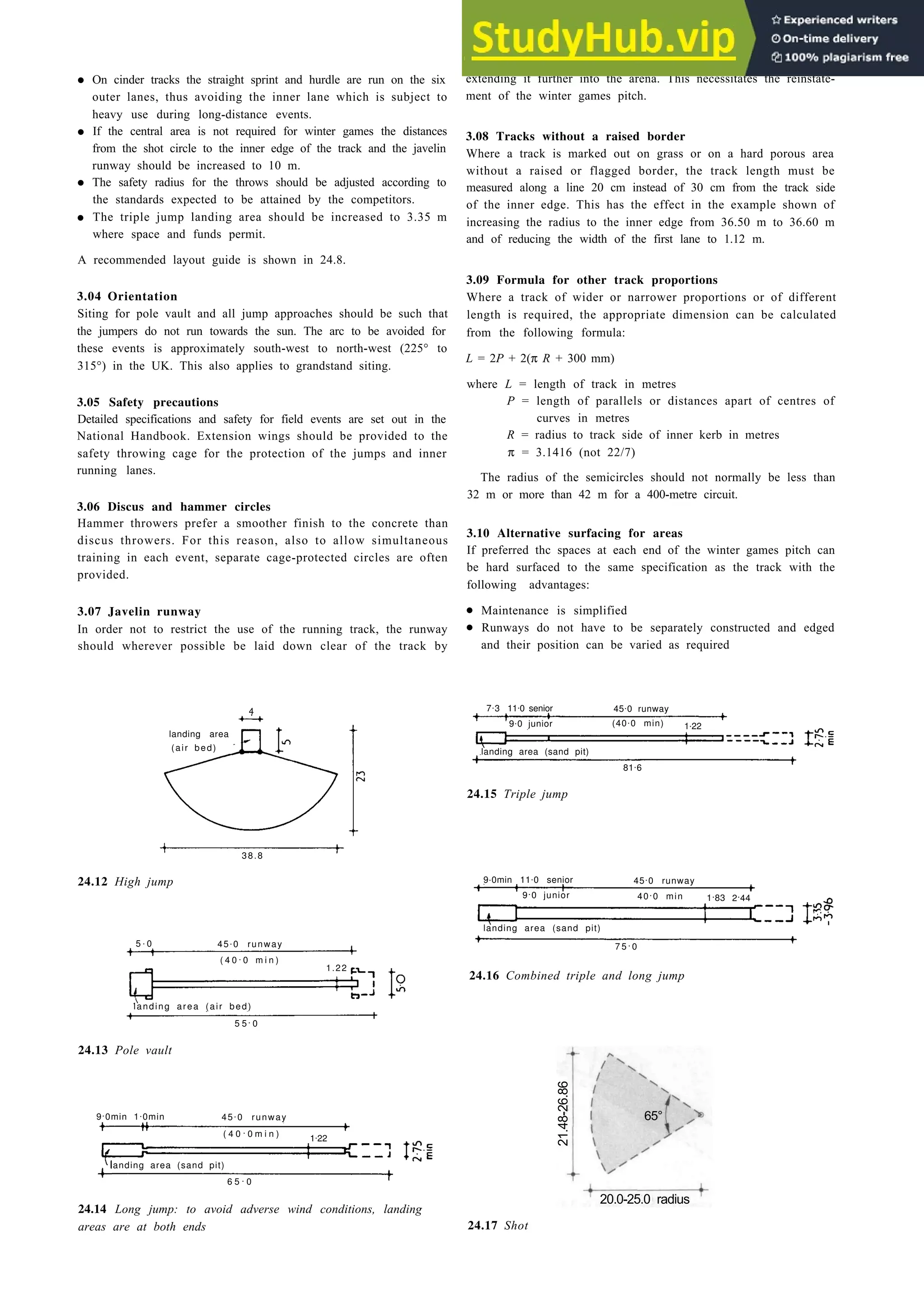
3.07 Maintenance
Buildings and the services and plant therein need constant
maintenance. Something frequently forgotten is the need for easy
access to certain areas. It is reasonable to assume that people
employed on maintenance work will be sufficiently agile and not
greatly above average size. The dimensions shown in 2.11 to 2.18
are therefore less than would be required for use by the general
public.
viewing distance
refer to 2.8b
47°
150
min
450
600
620
[781,5] [859,5]
[1075,5]
normal
minimum
distance
from screen
400 mm
minimum
distance
from touch
screen
300 mm
preferred
visual angle
between 20
and 22 minutes
700
1300
1900
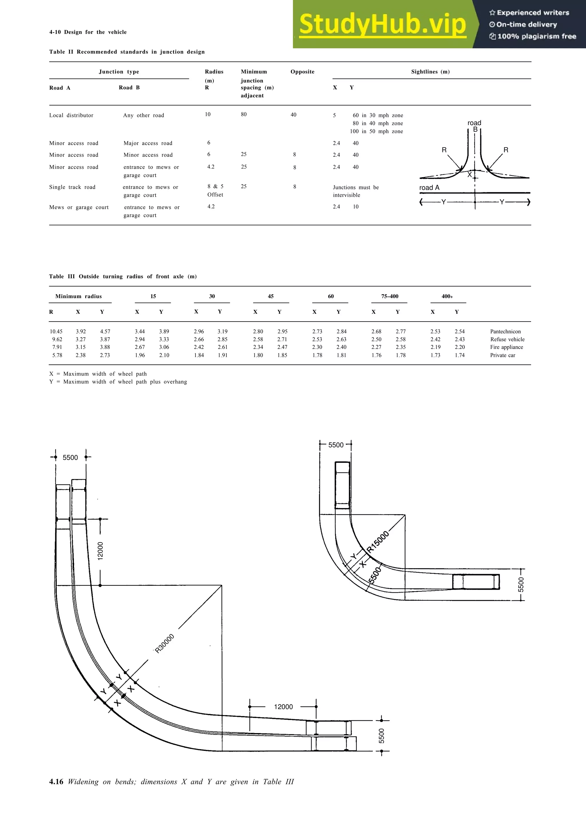
500](https://image.slidesharecdn.com/architectureebookmetrichandbookplanninganddesigndata-230807180049-33007df6/75/Architecture-Ebook-Metric-Handbook-Planning-and-Design-Data-pdf-28-2048.jpg)


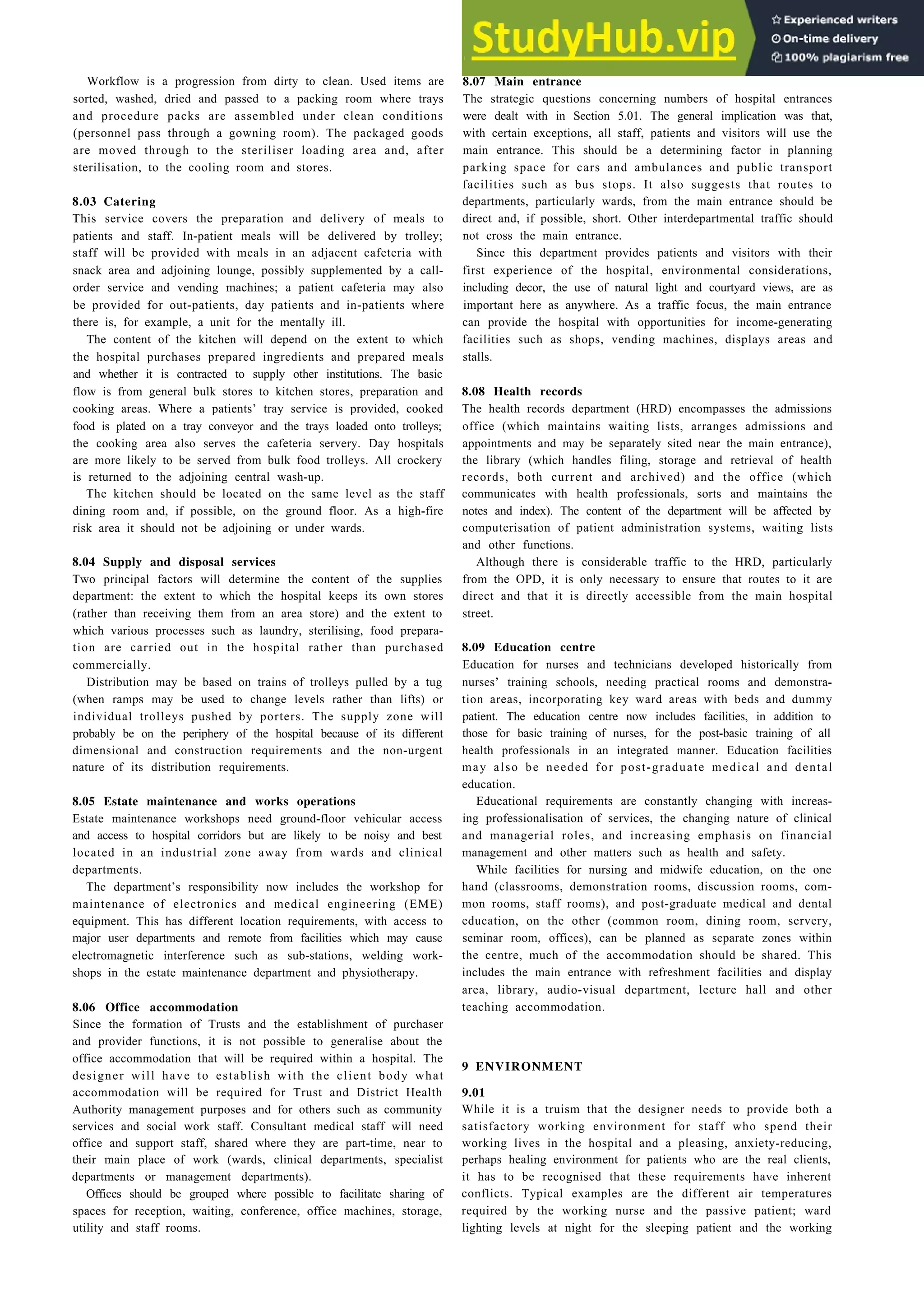


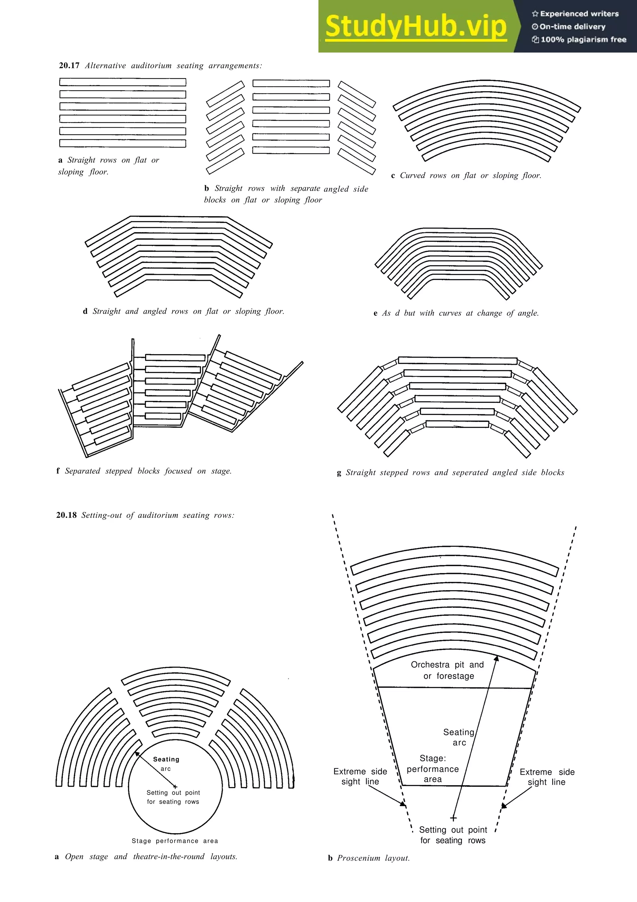


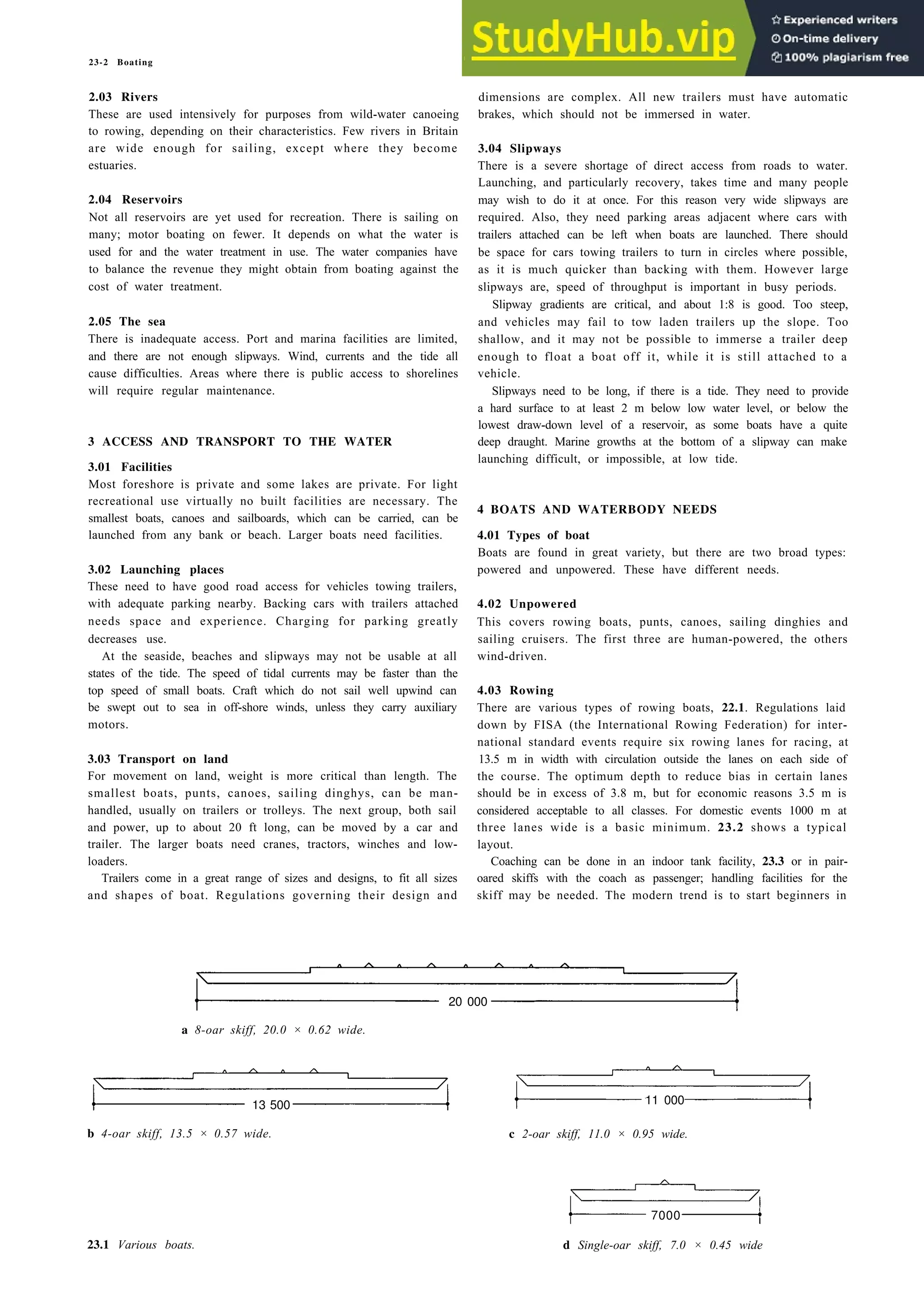
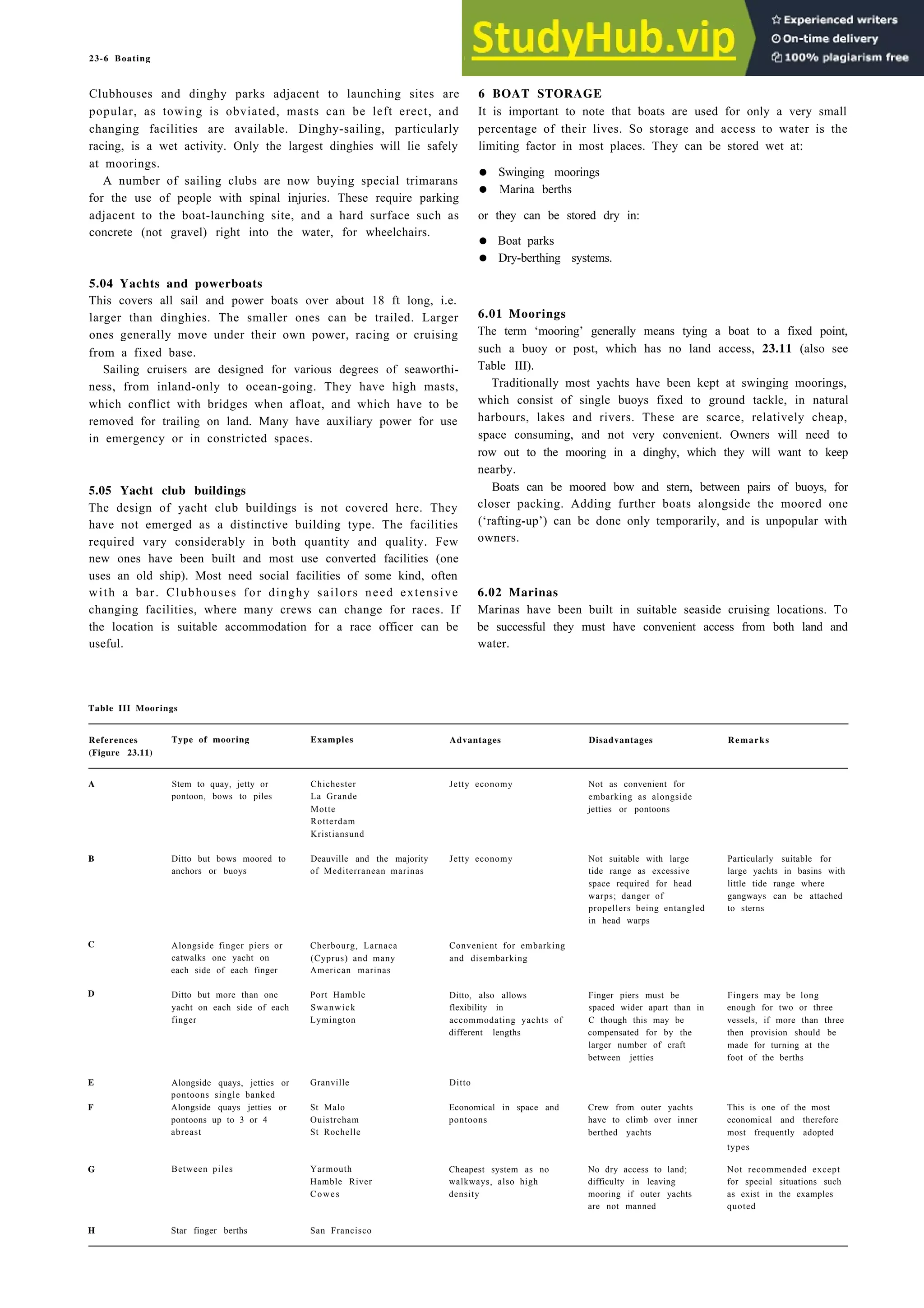
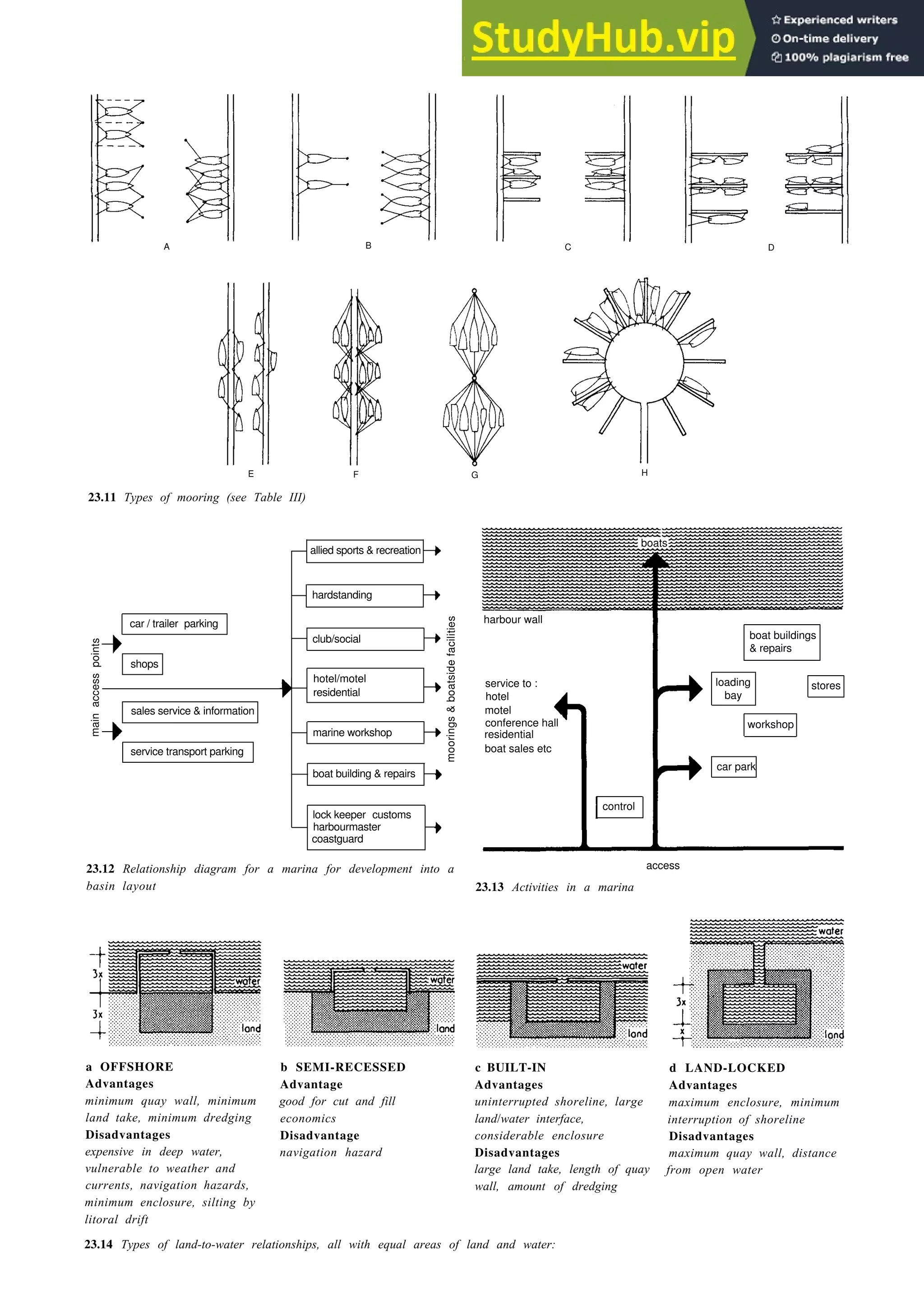
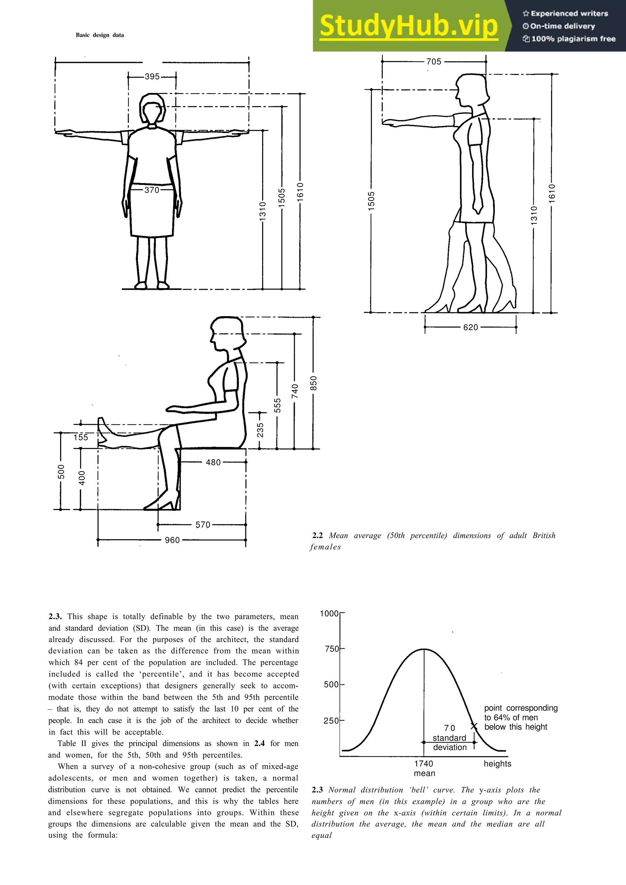
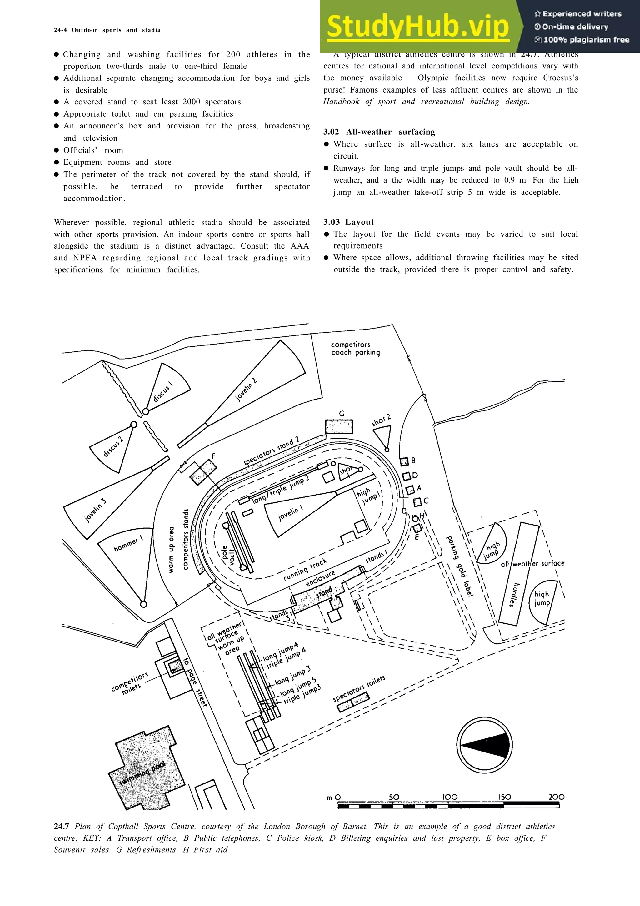
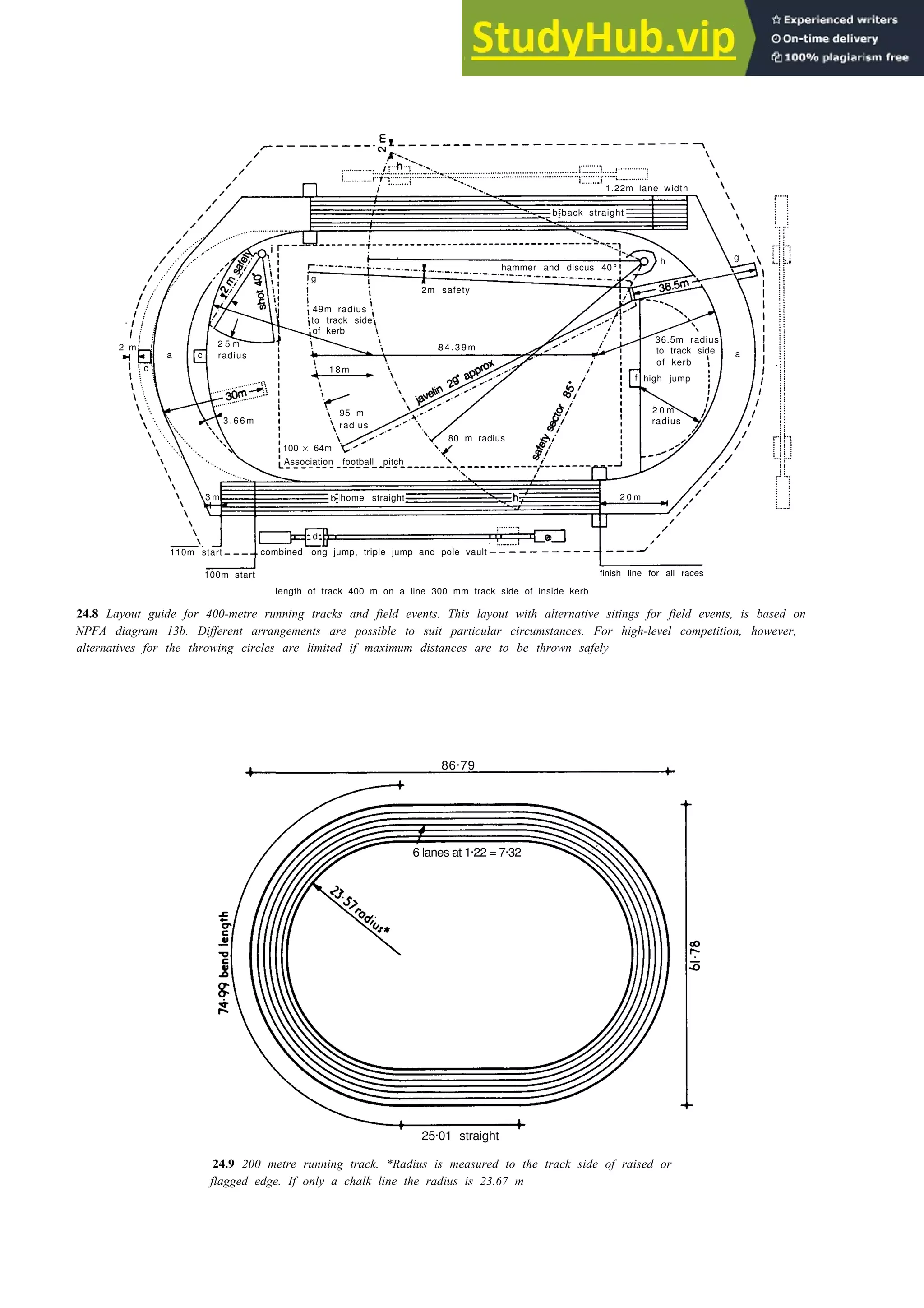
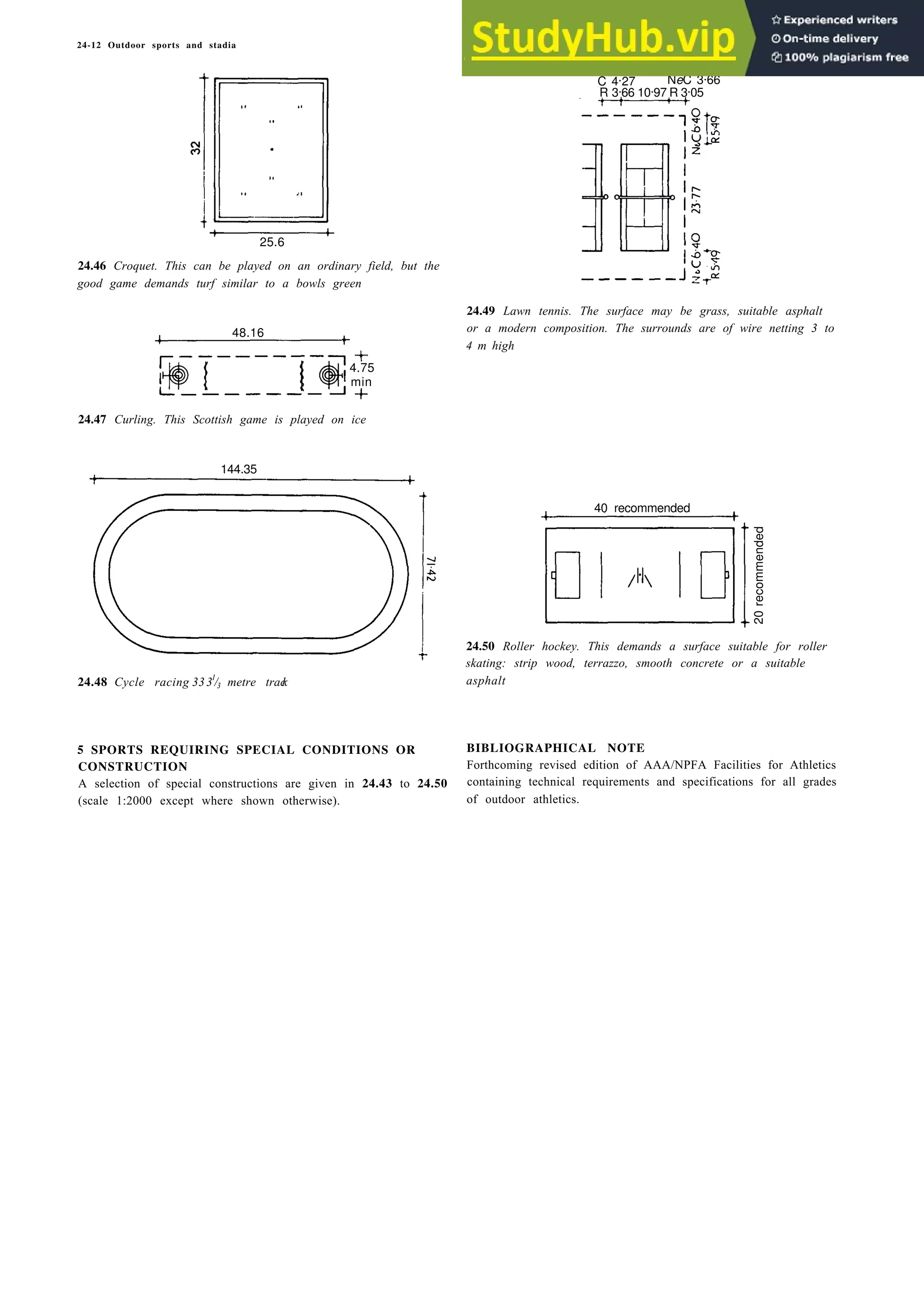
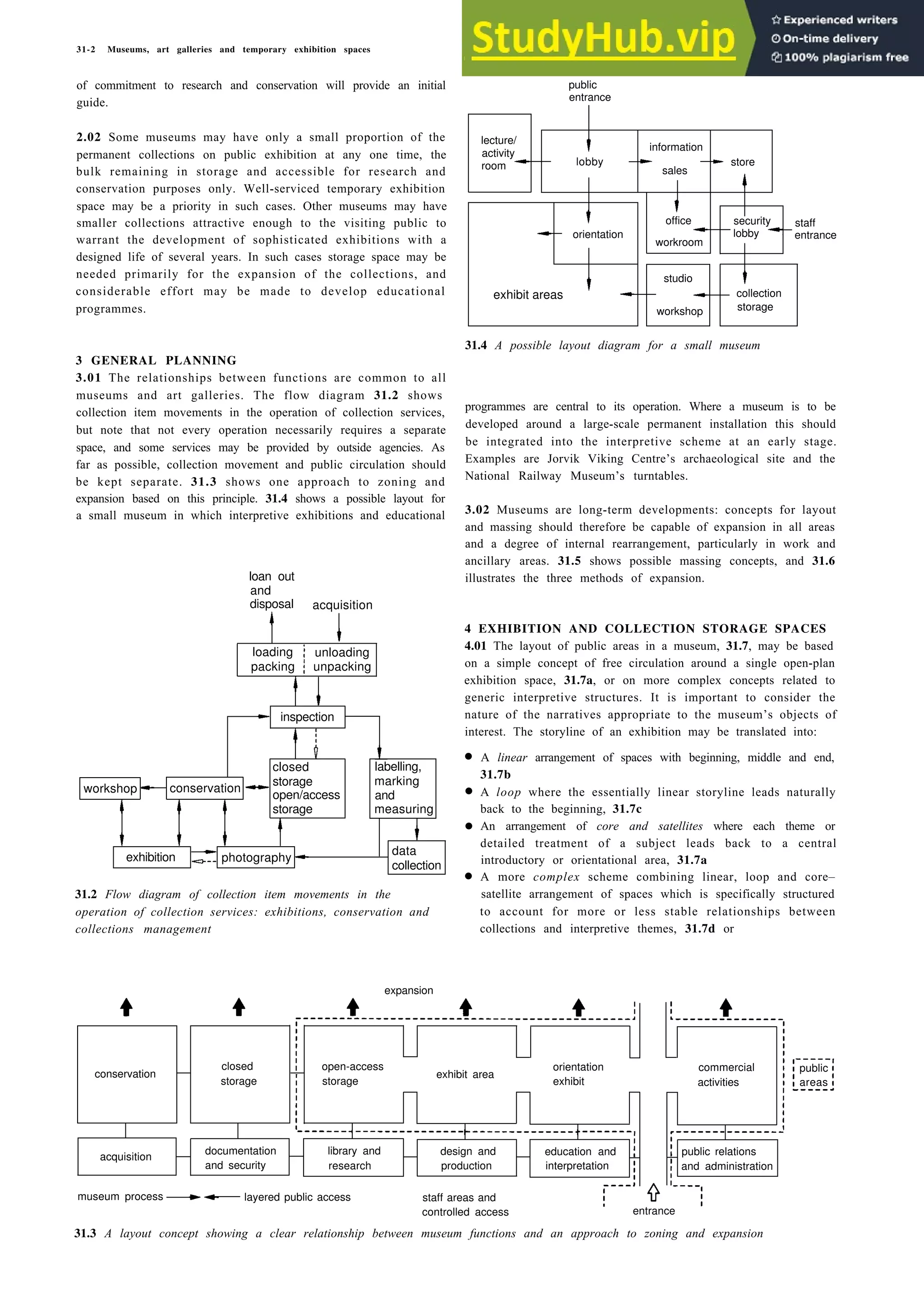
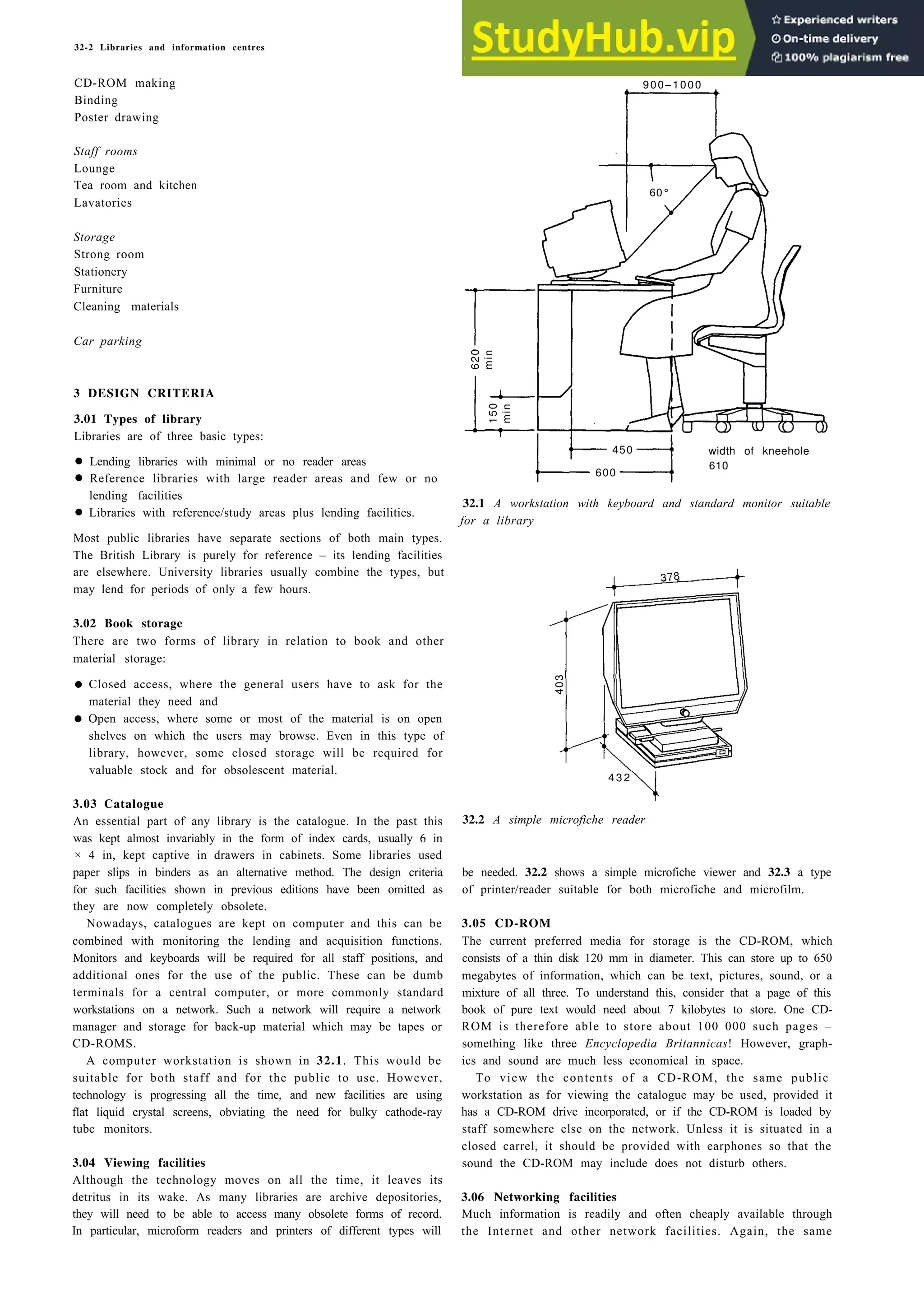
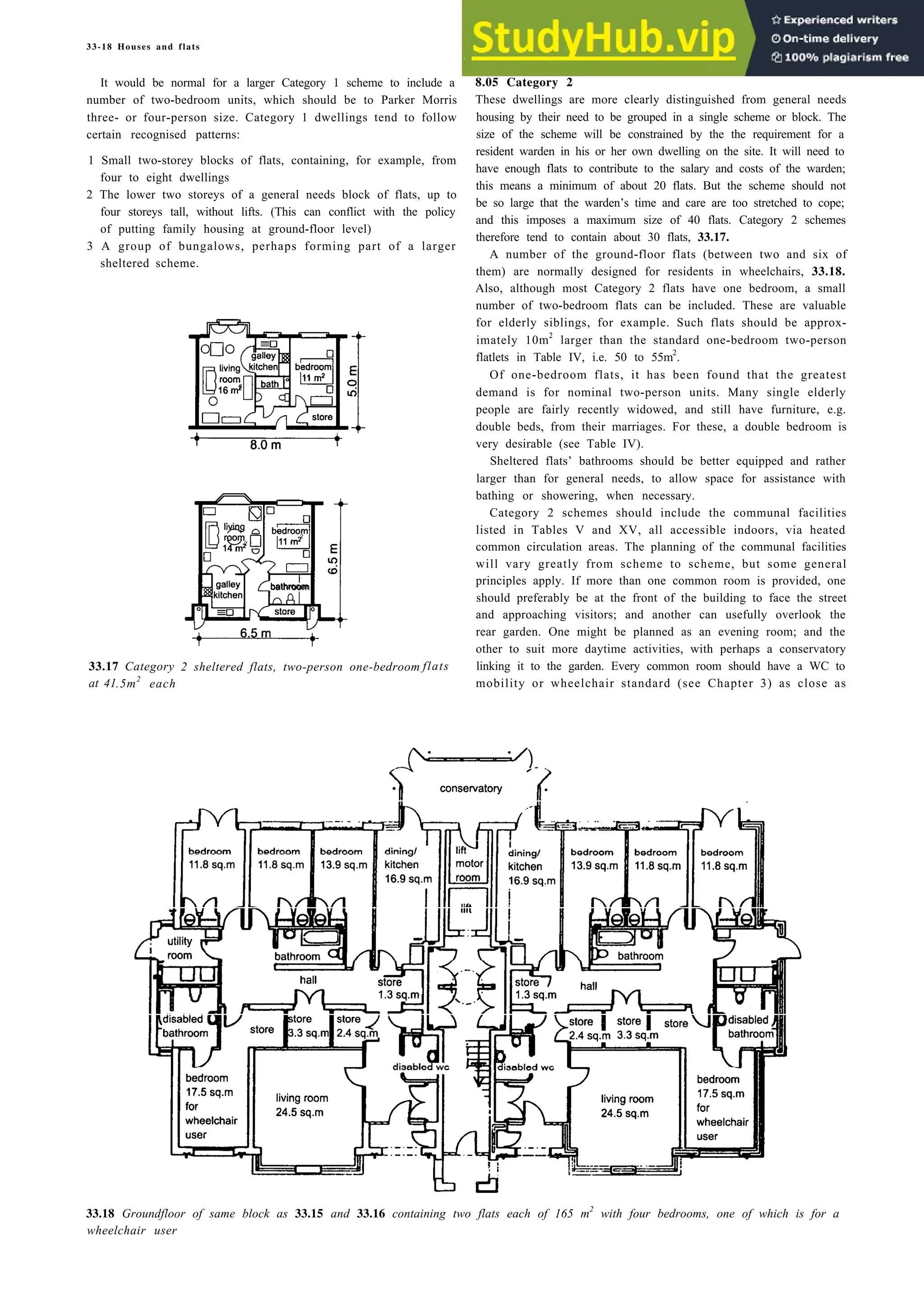
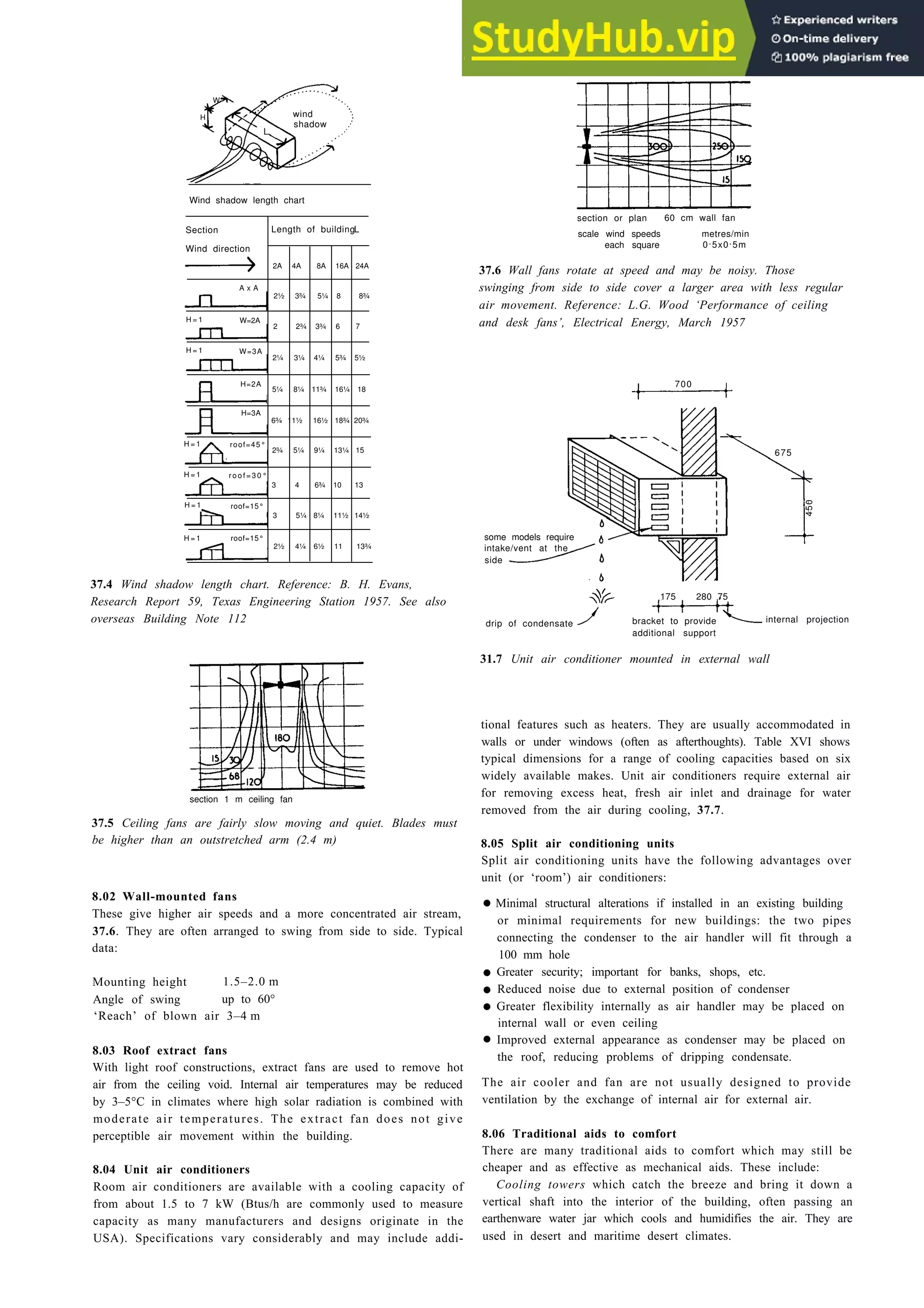
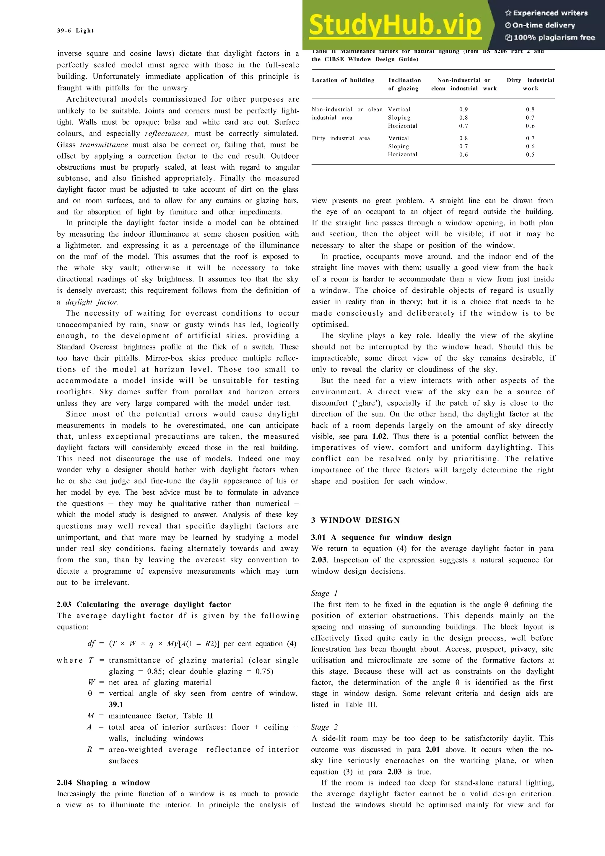
![23-8 Boating
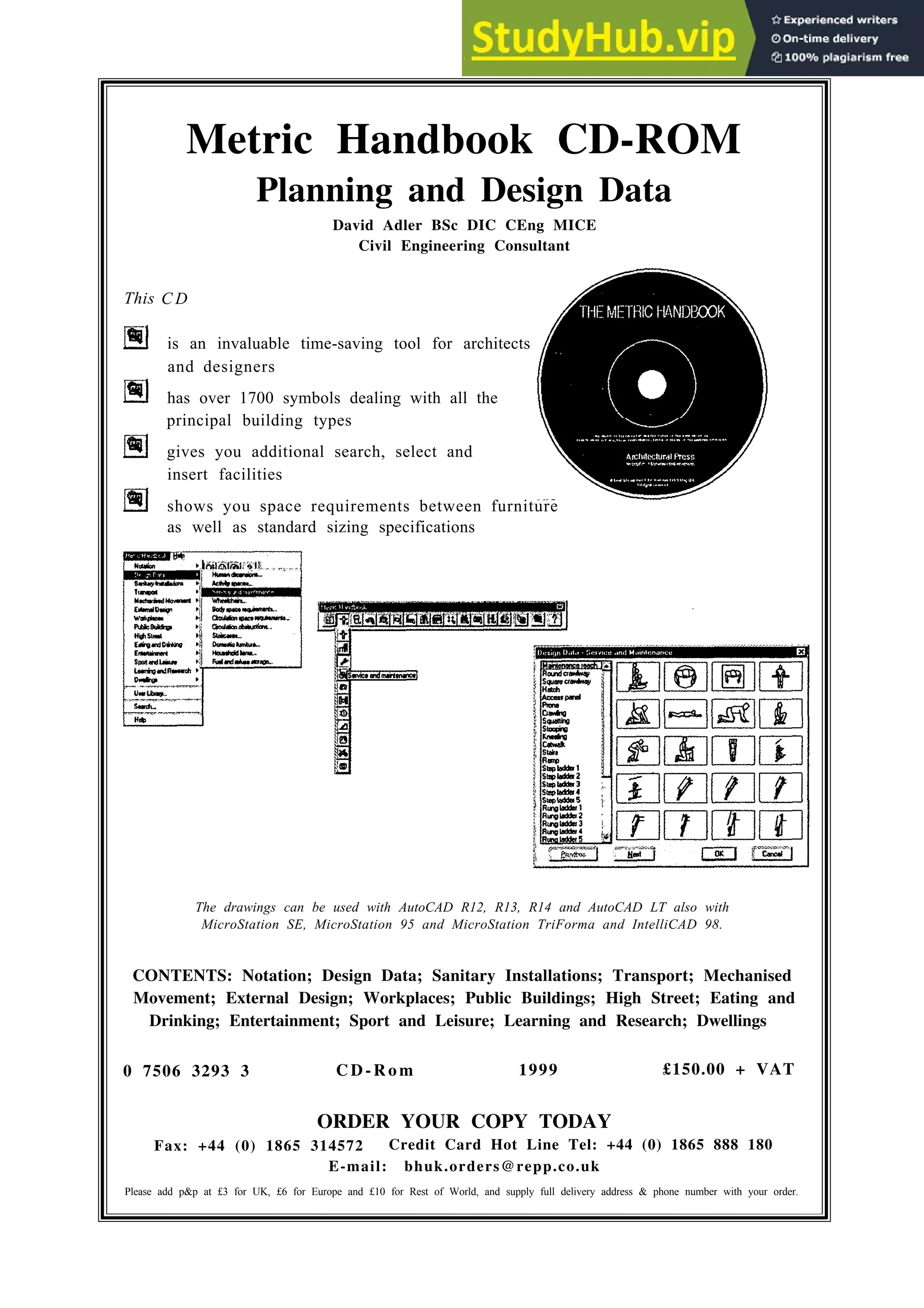
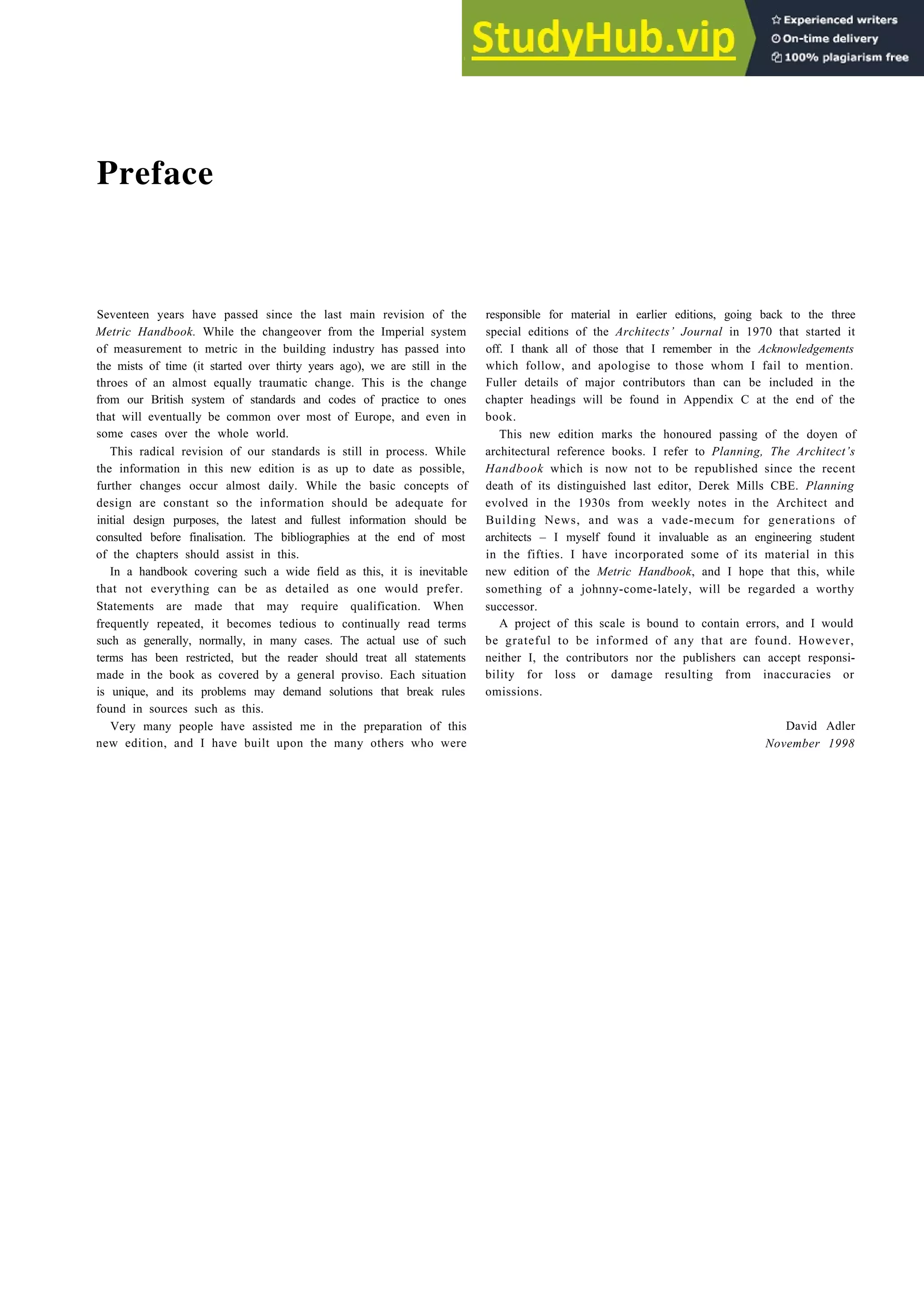
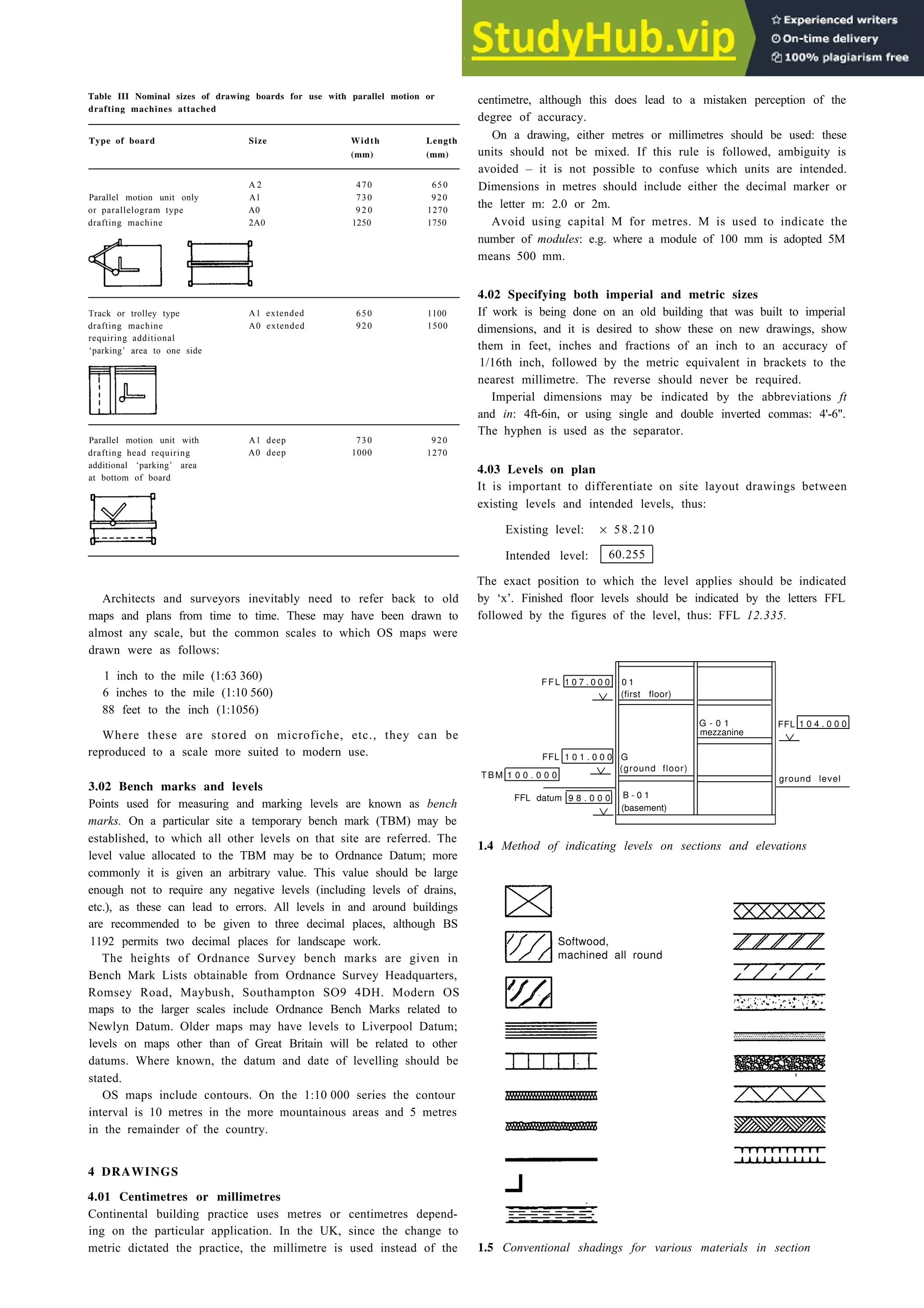
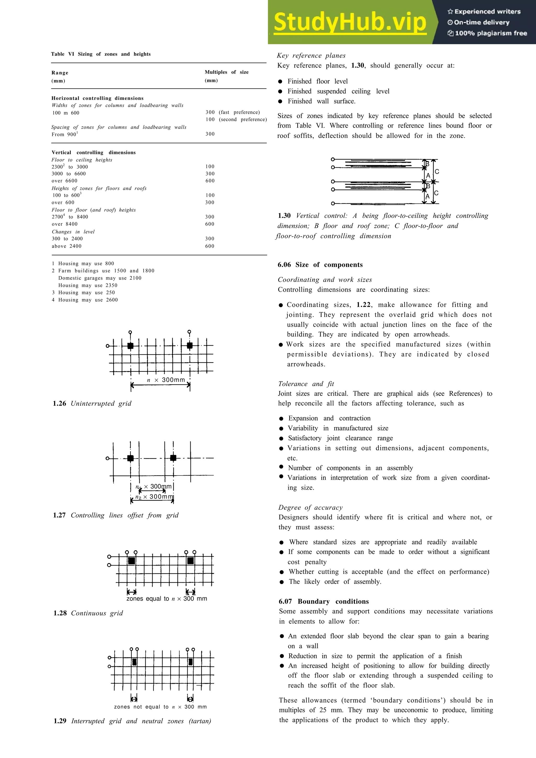
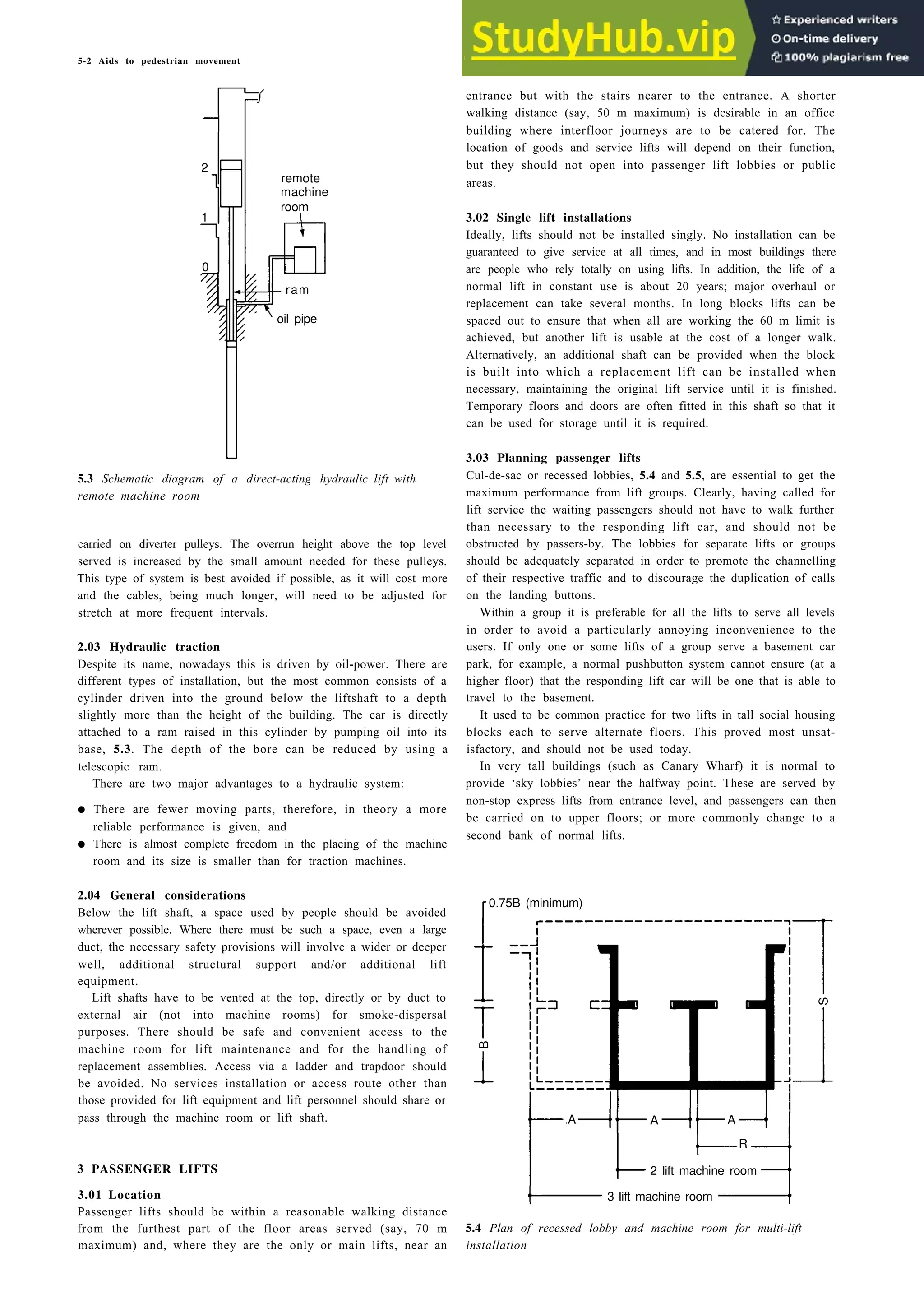
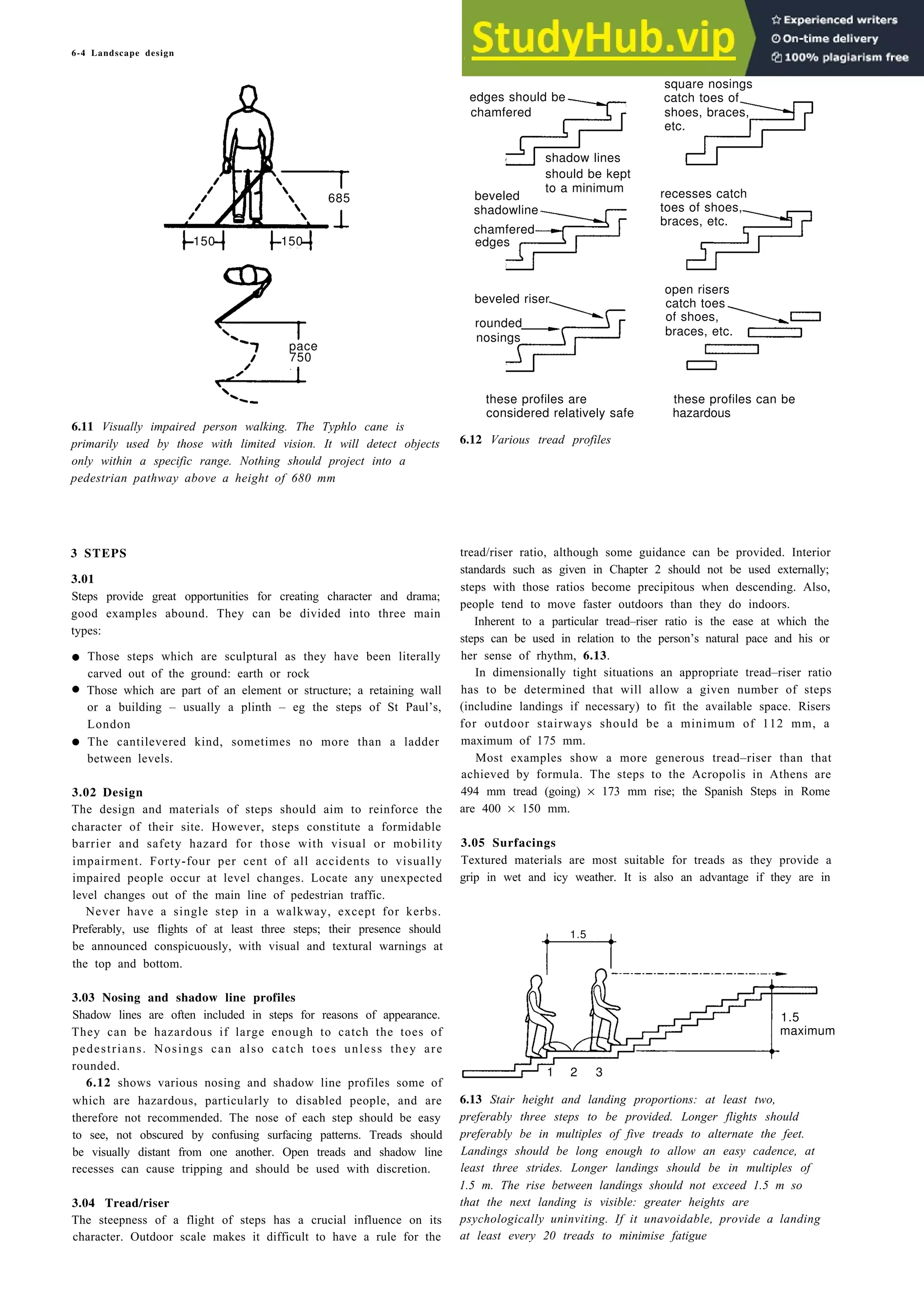
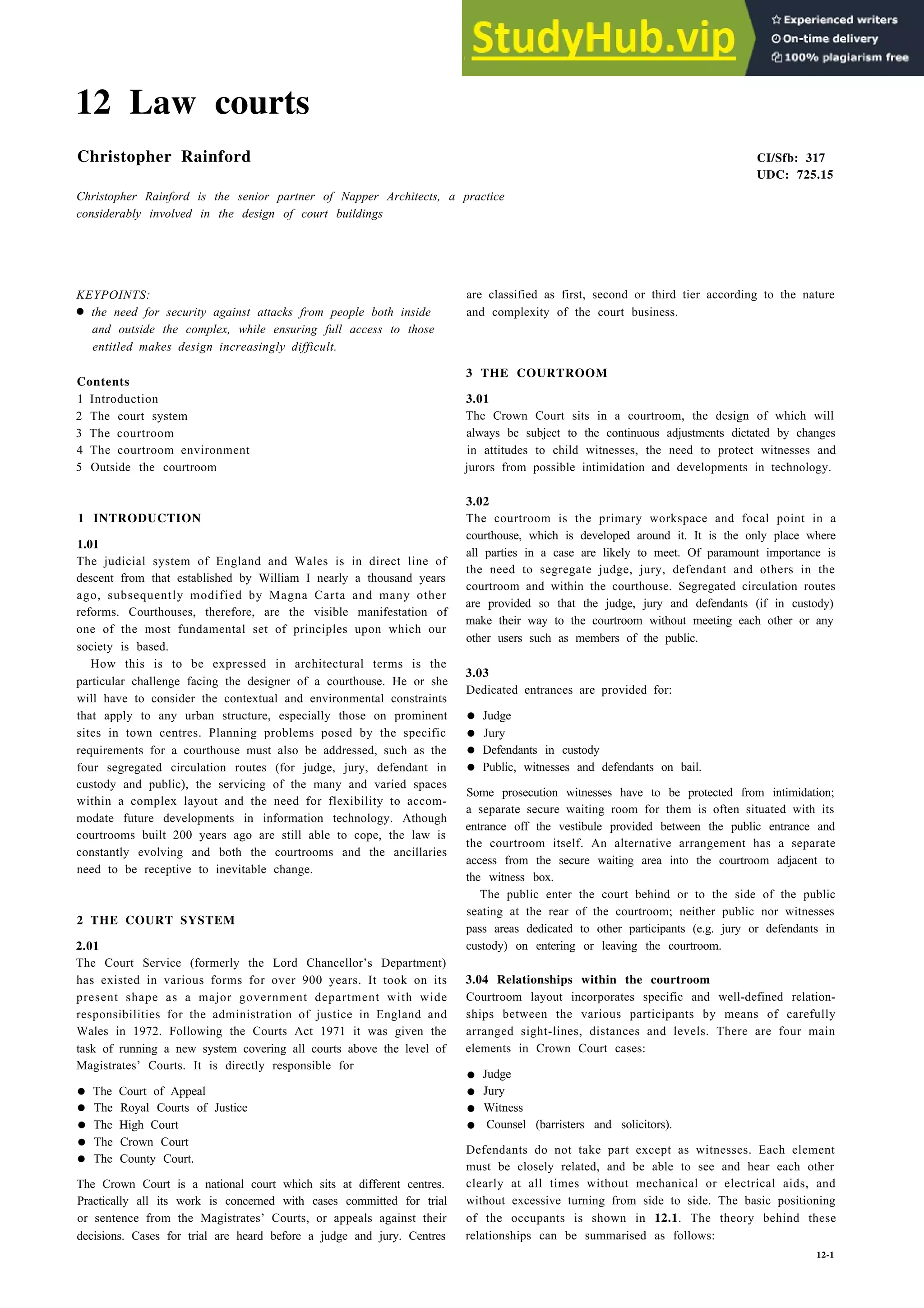
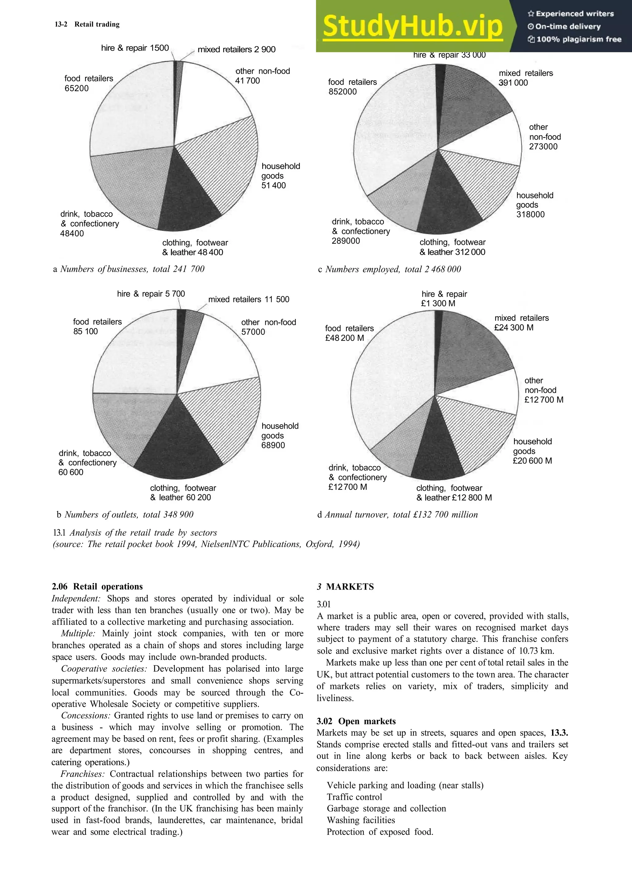
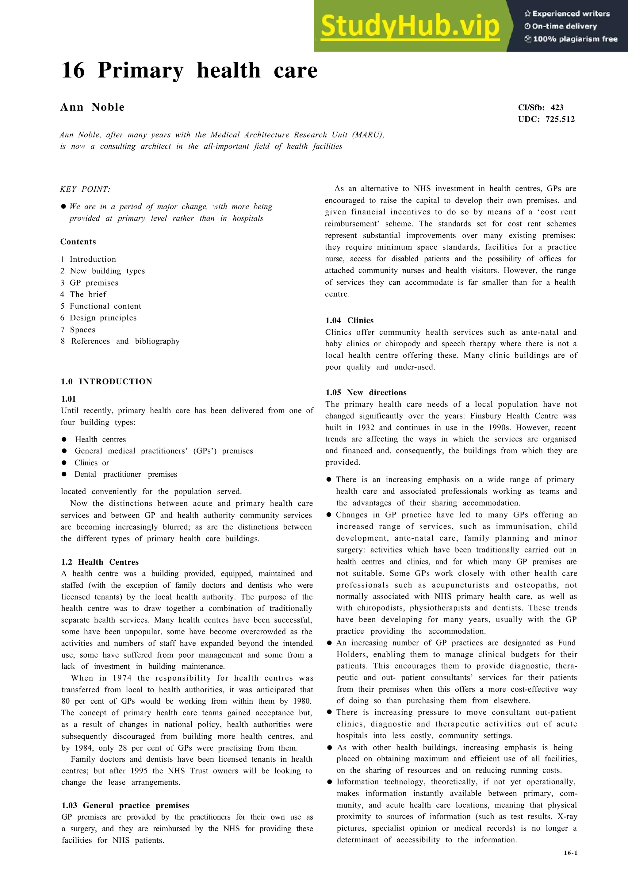
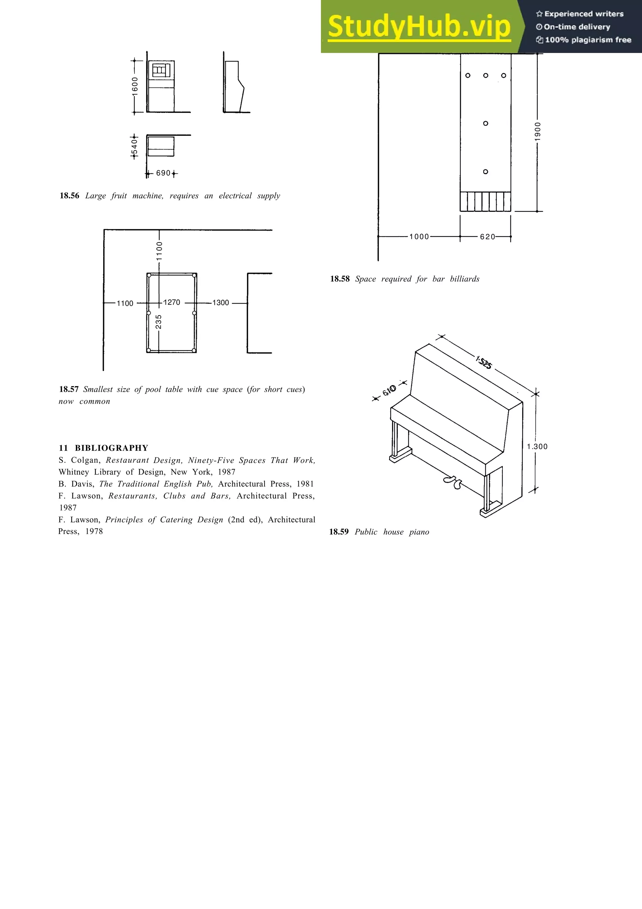
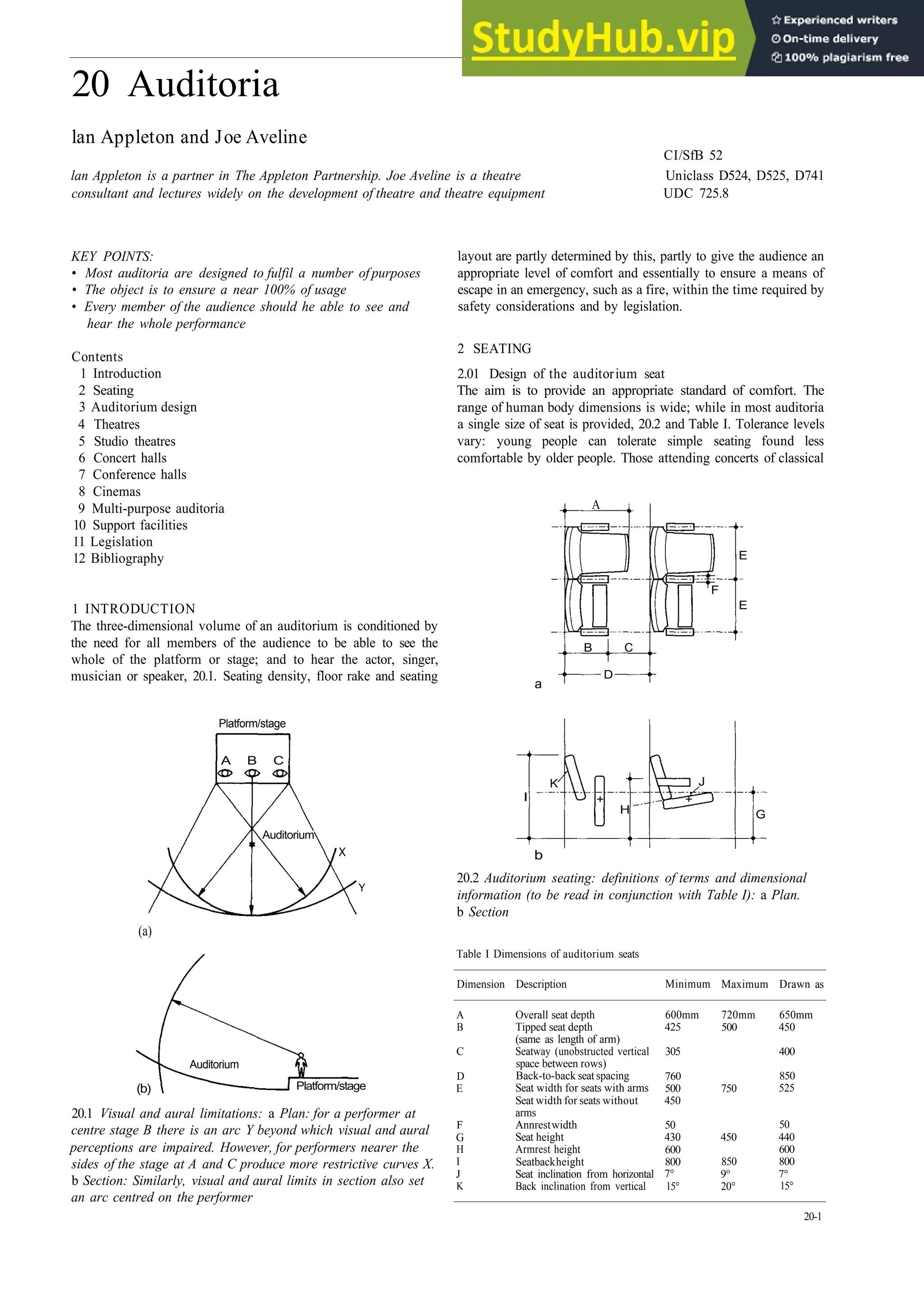
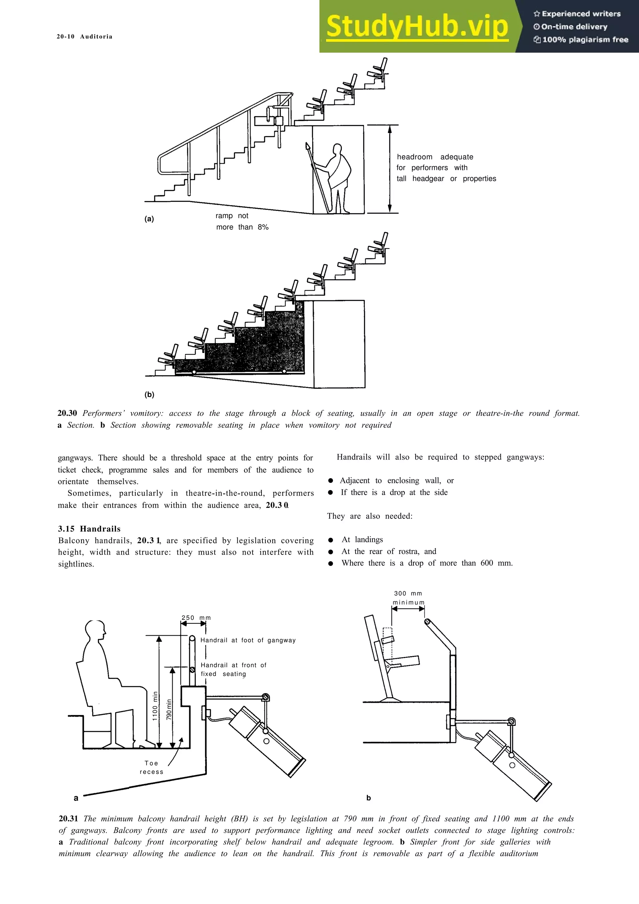
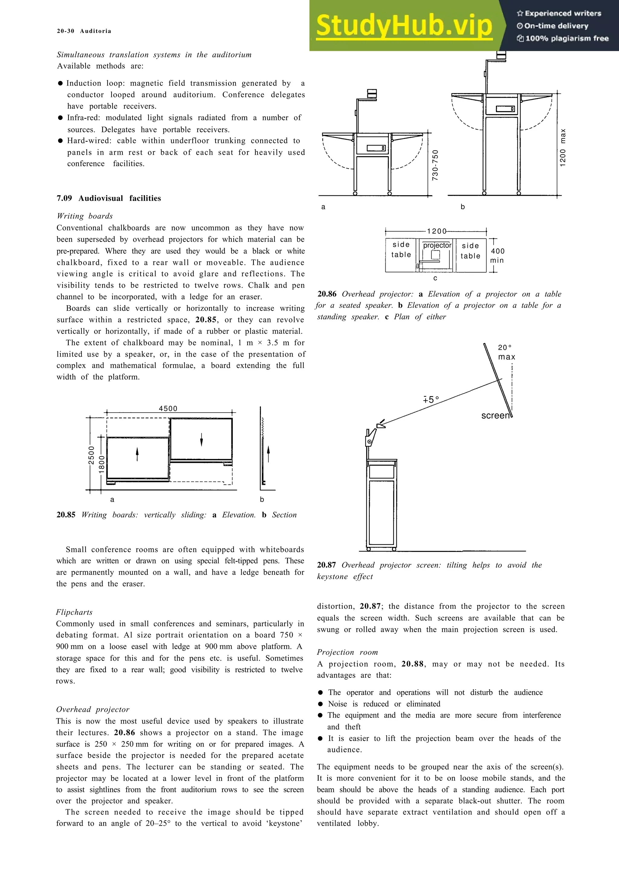
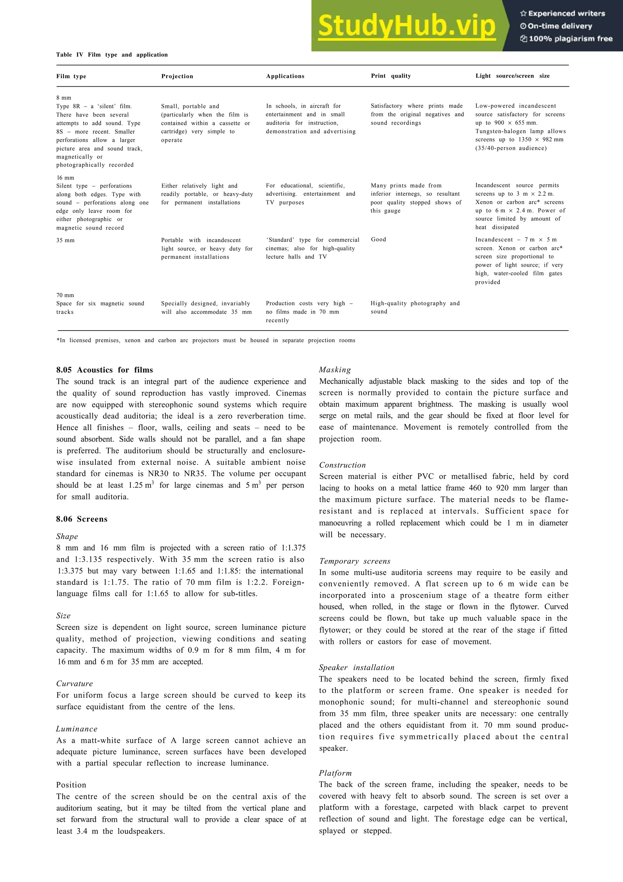
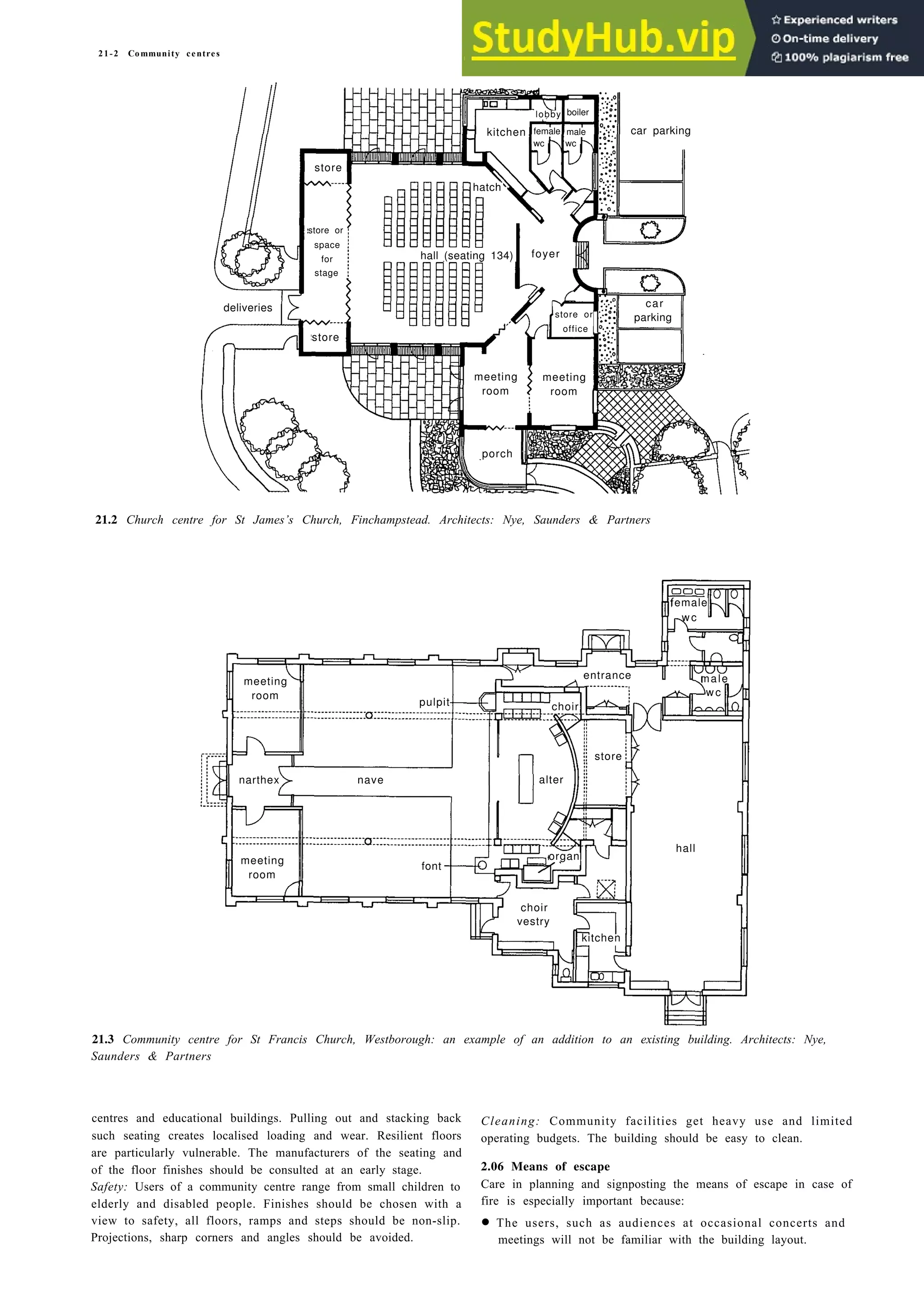
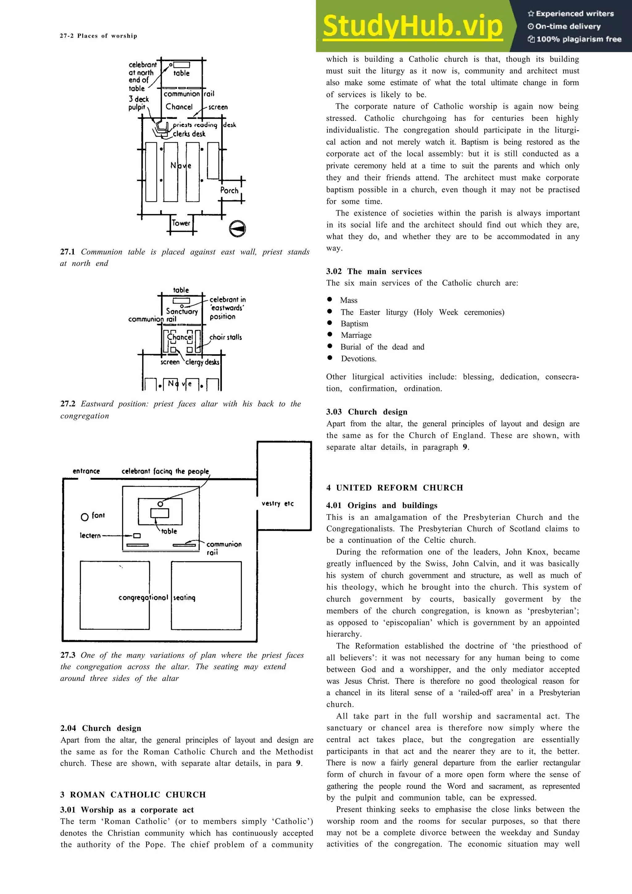
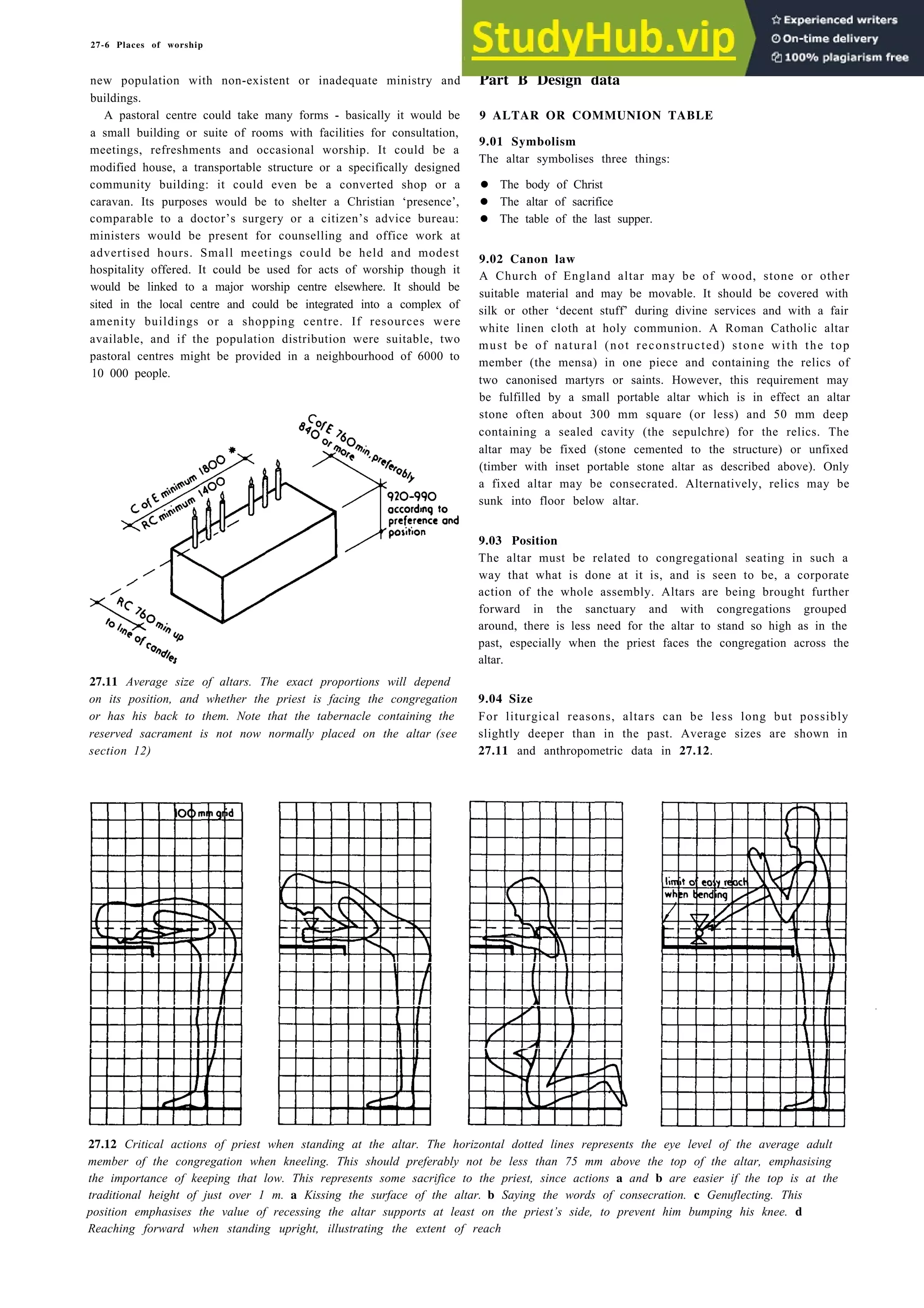
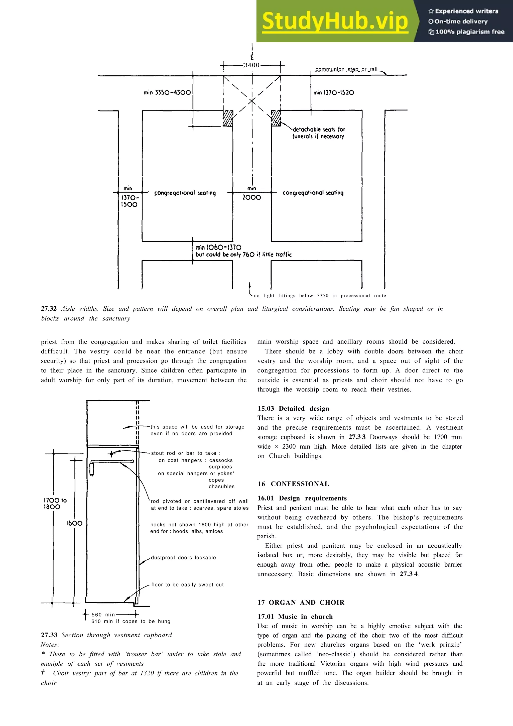
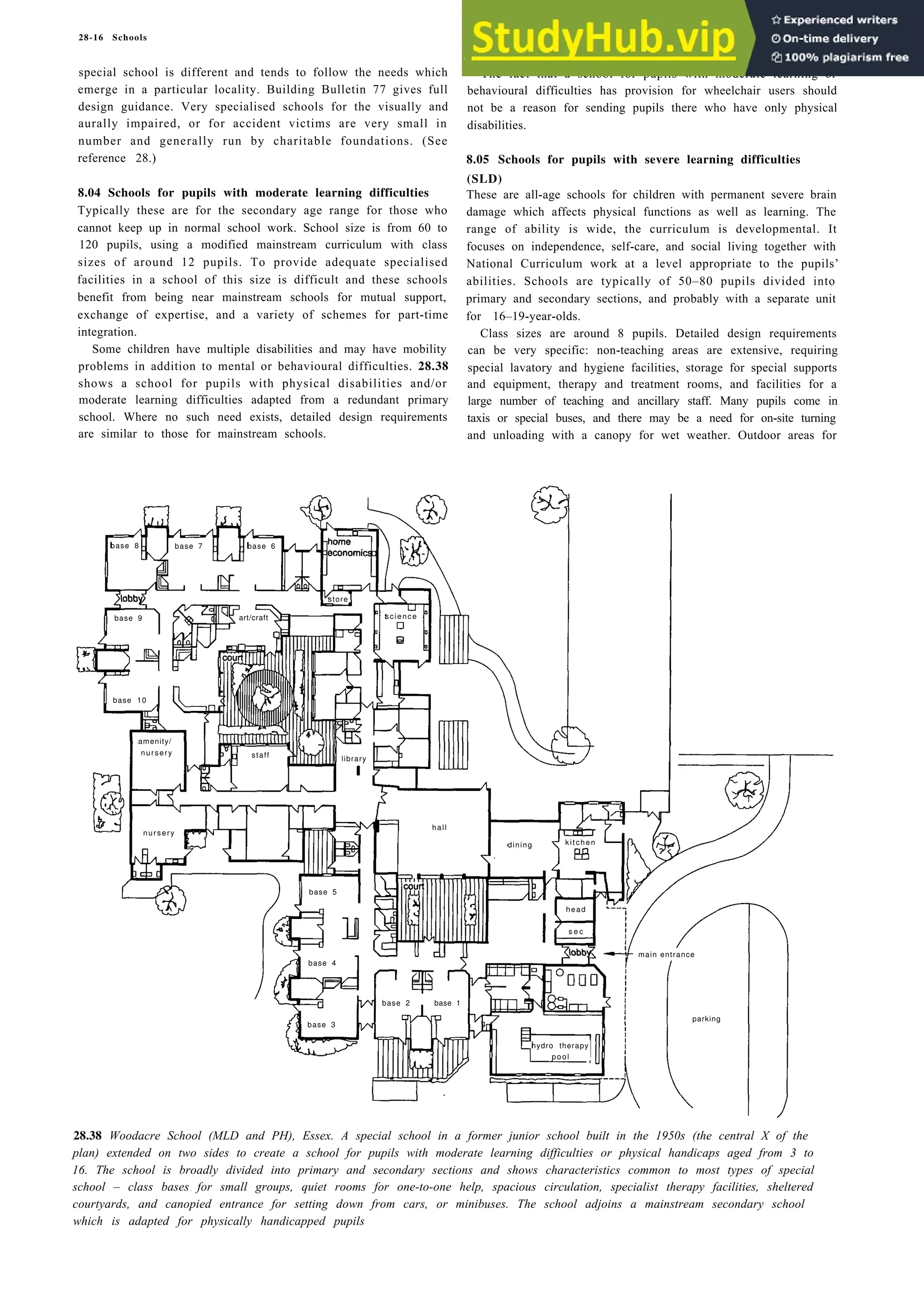
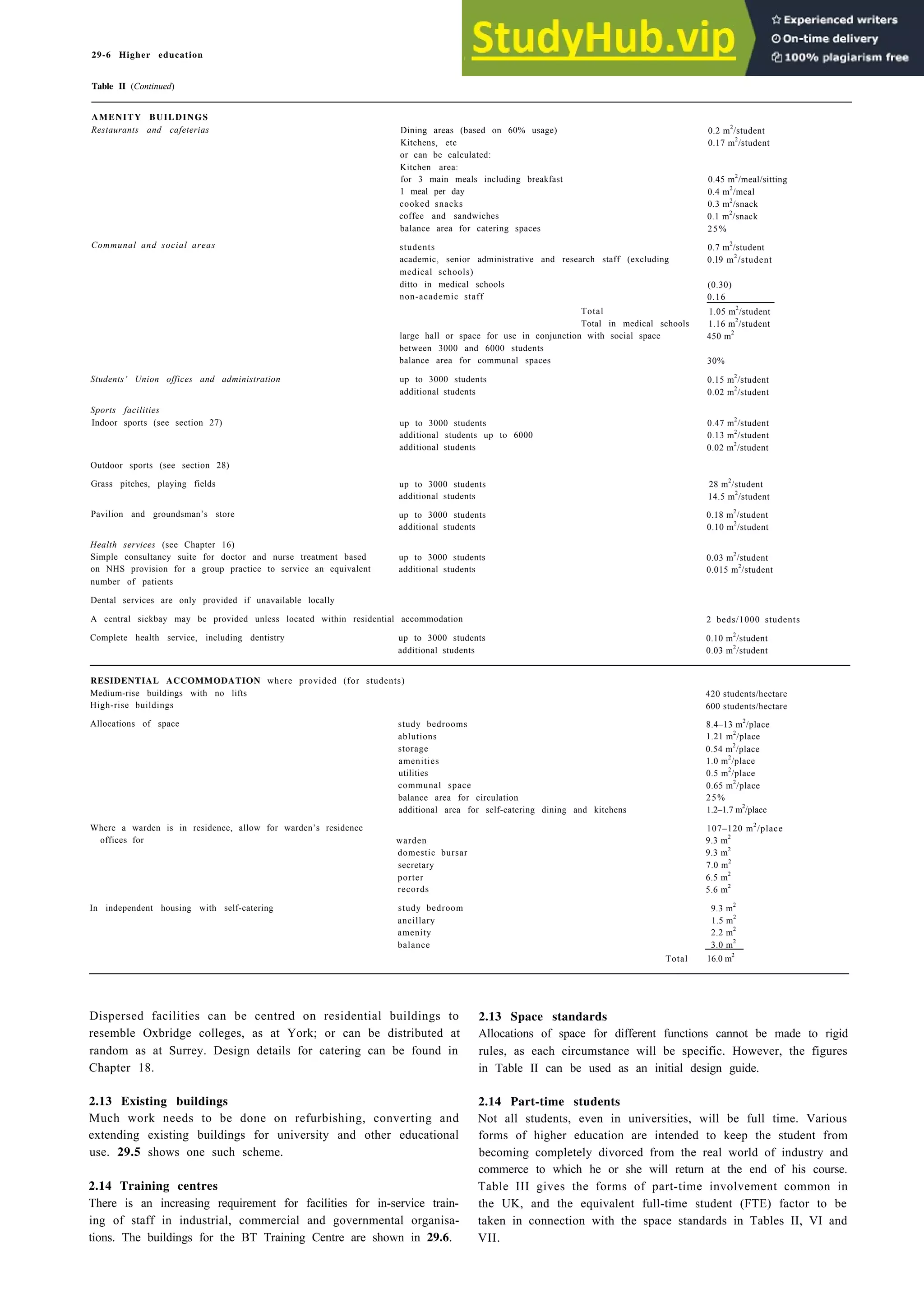
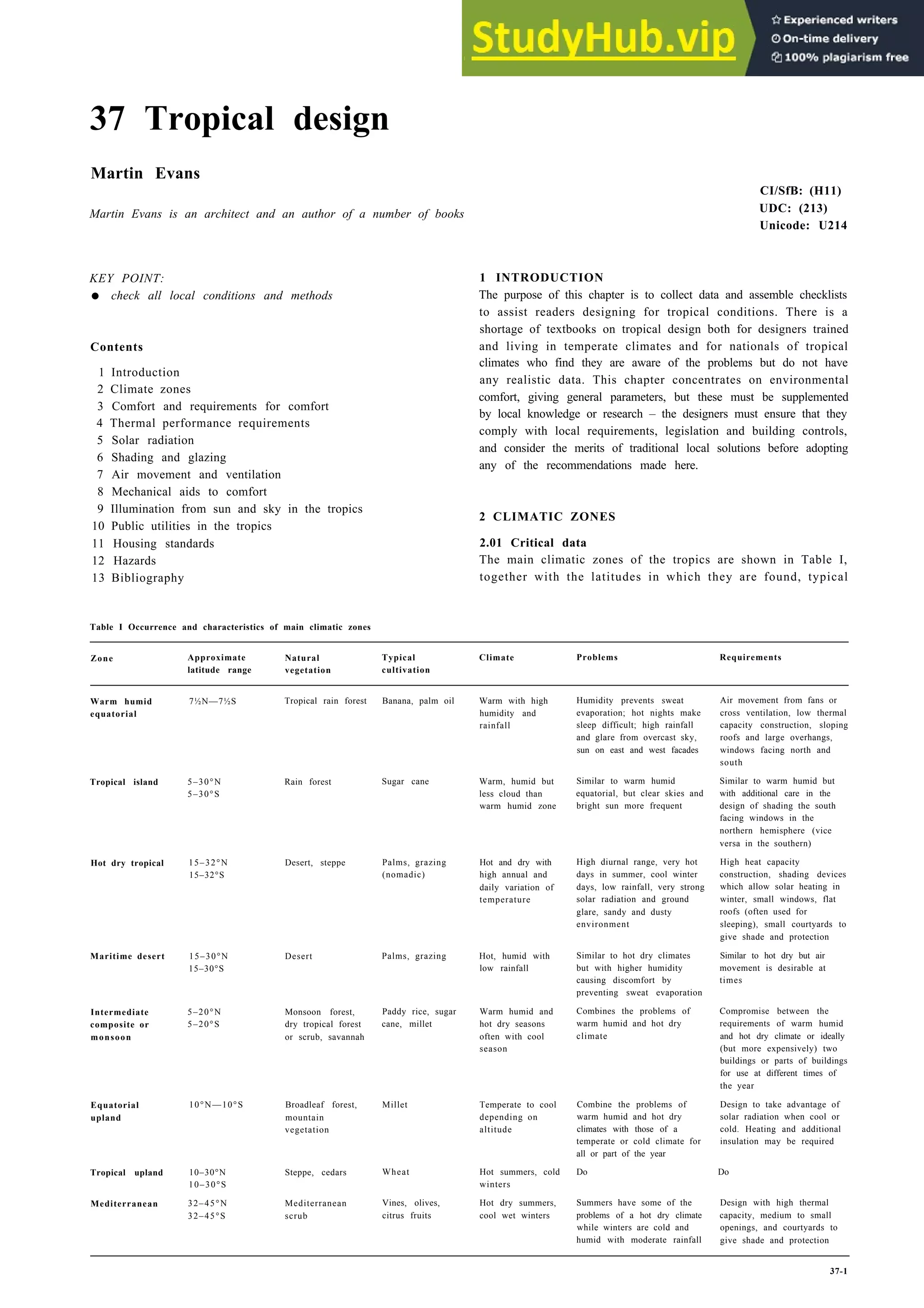
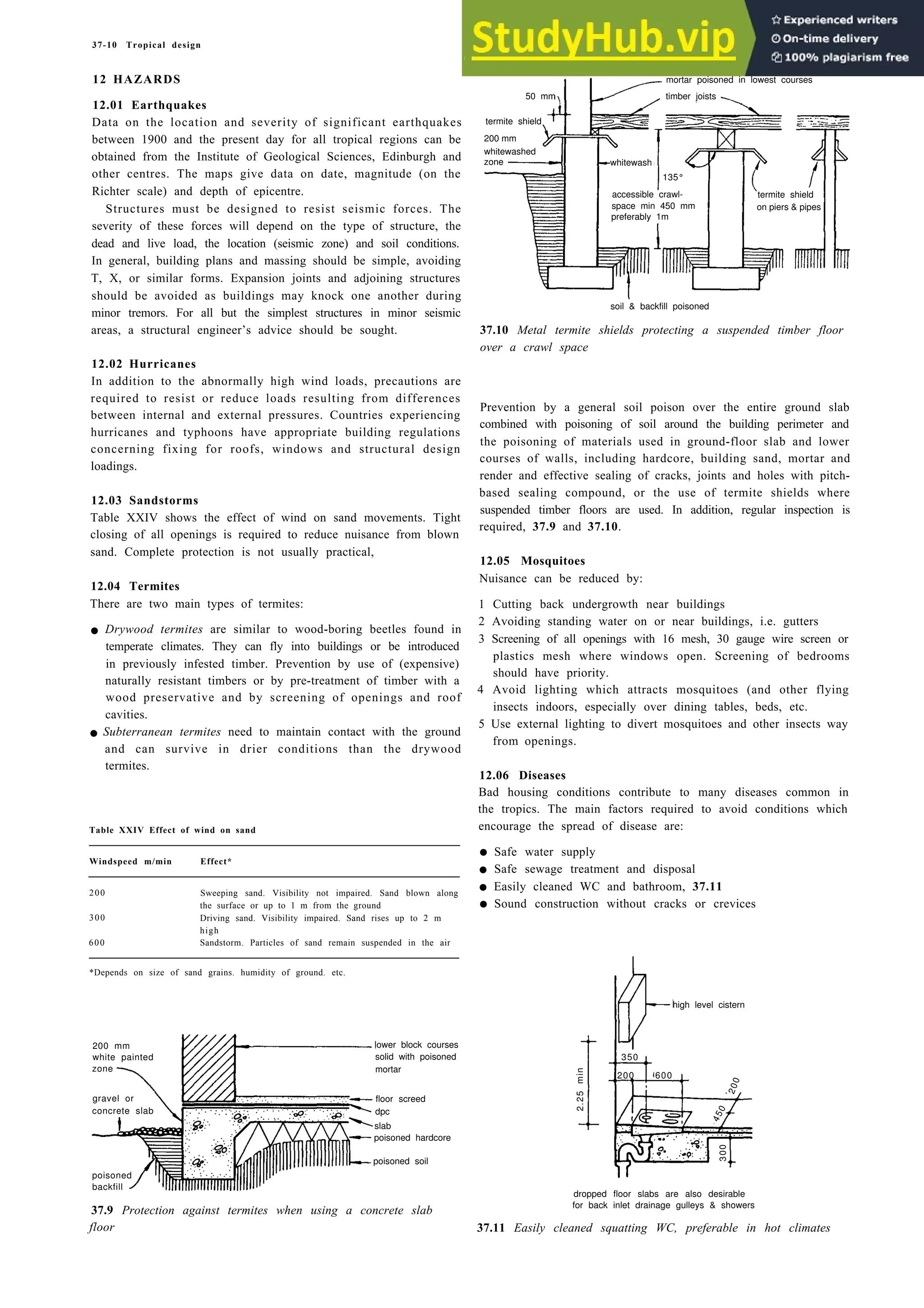
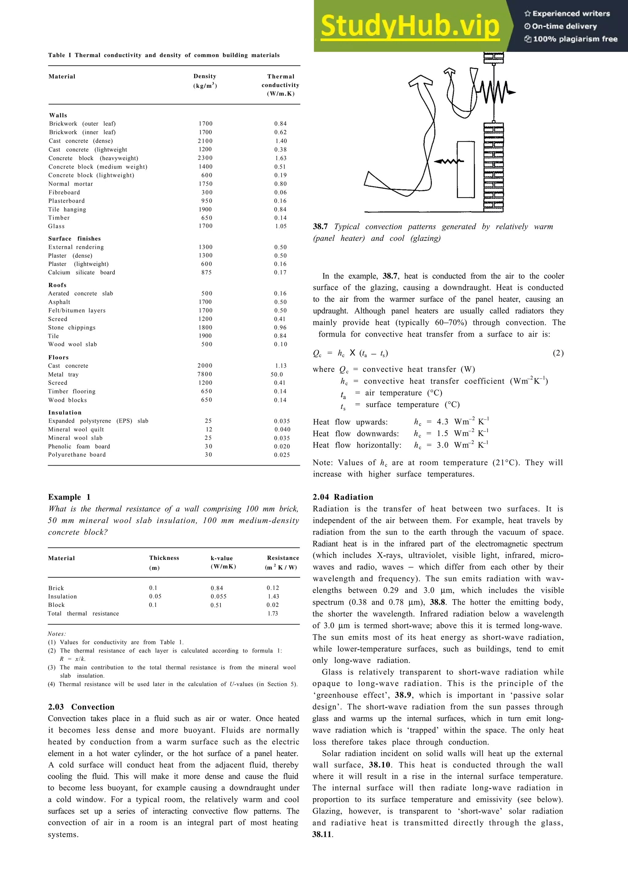
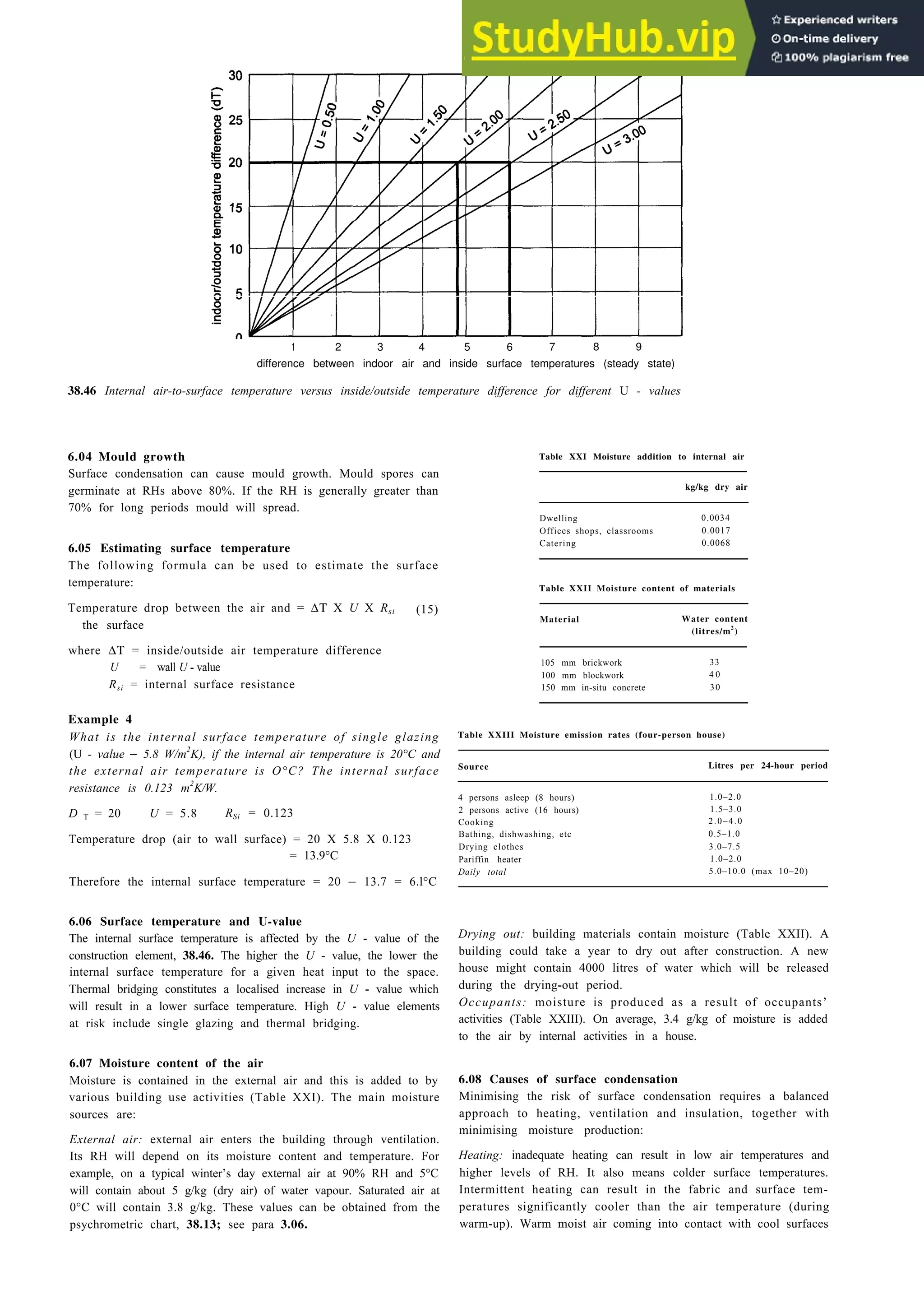
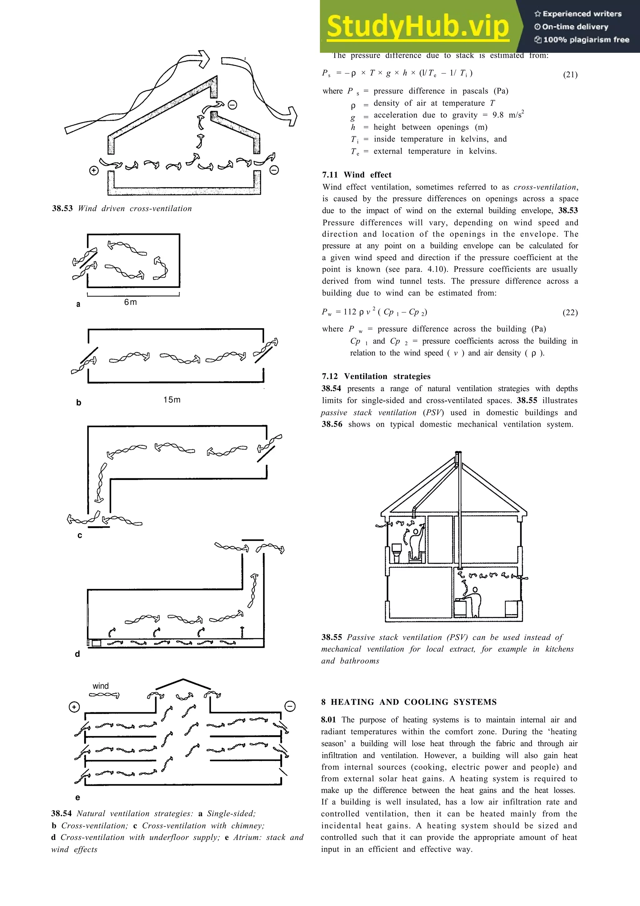
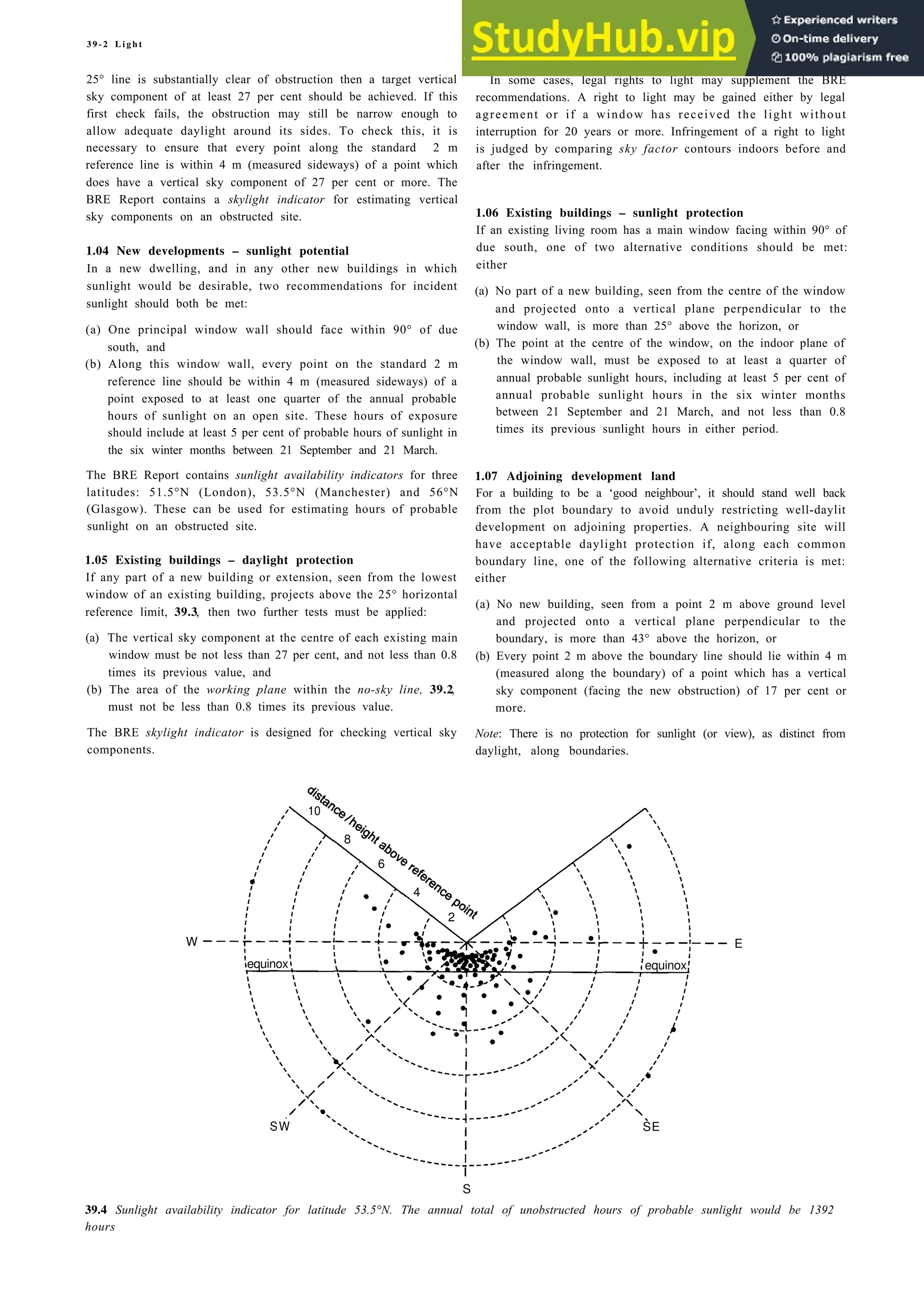
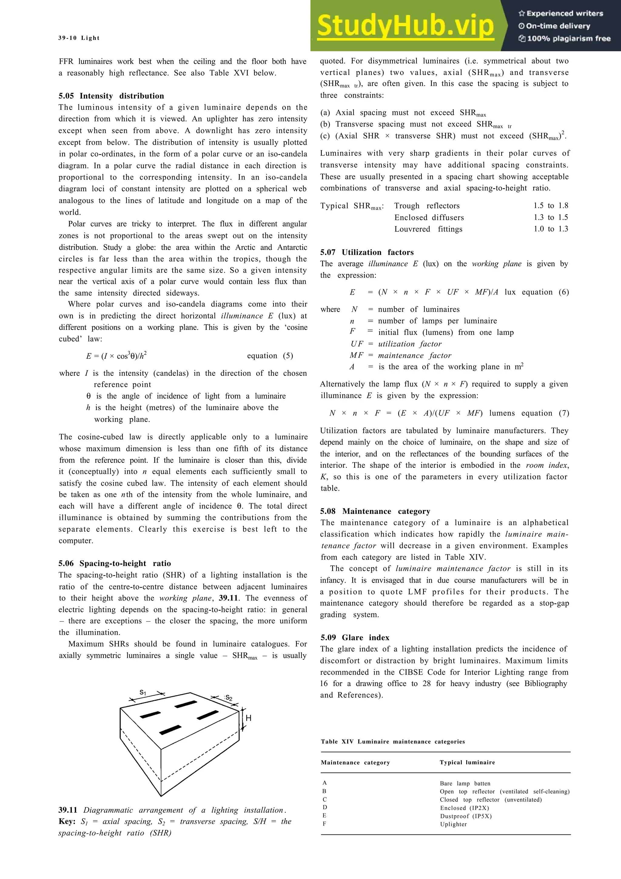
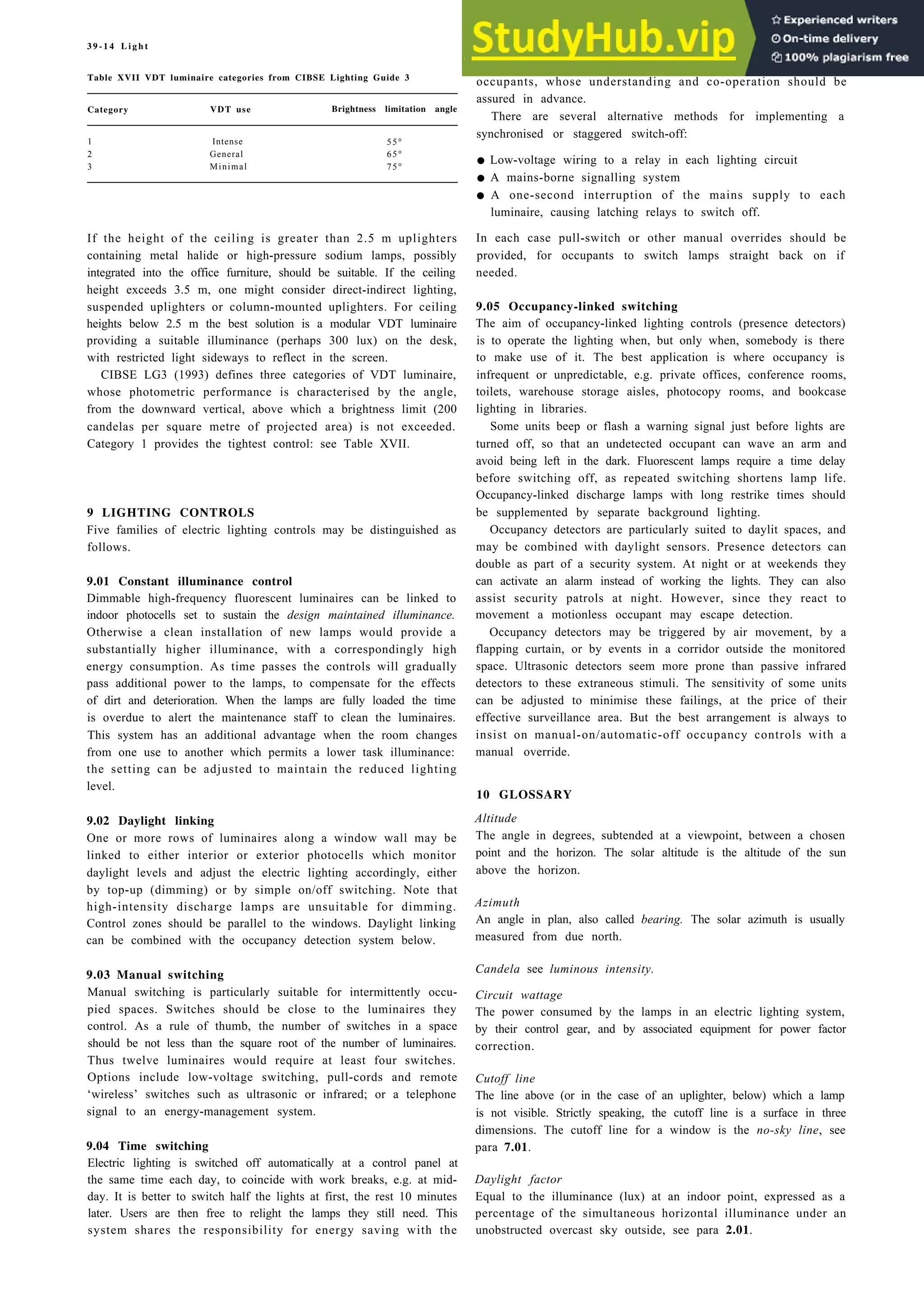
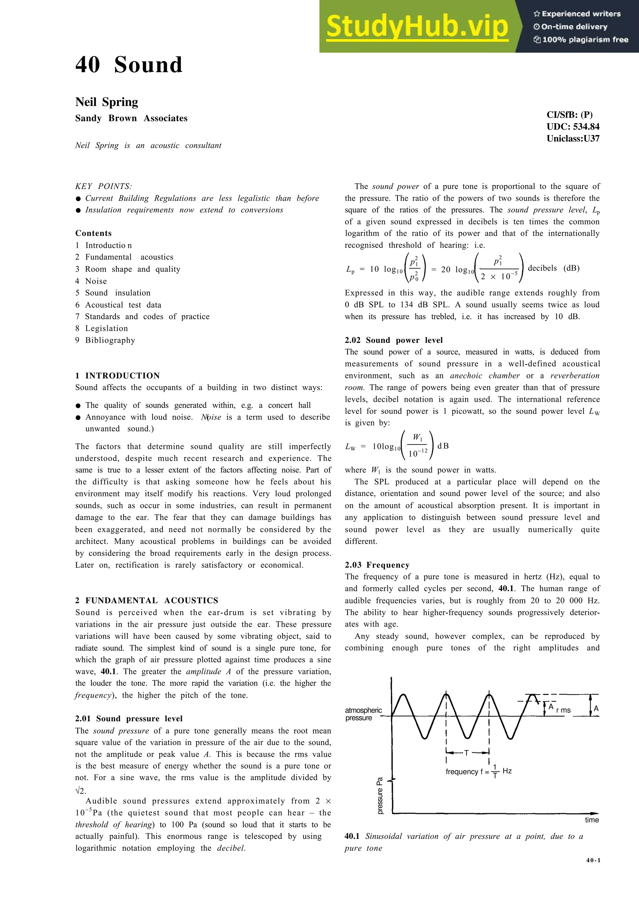
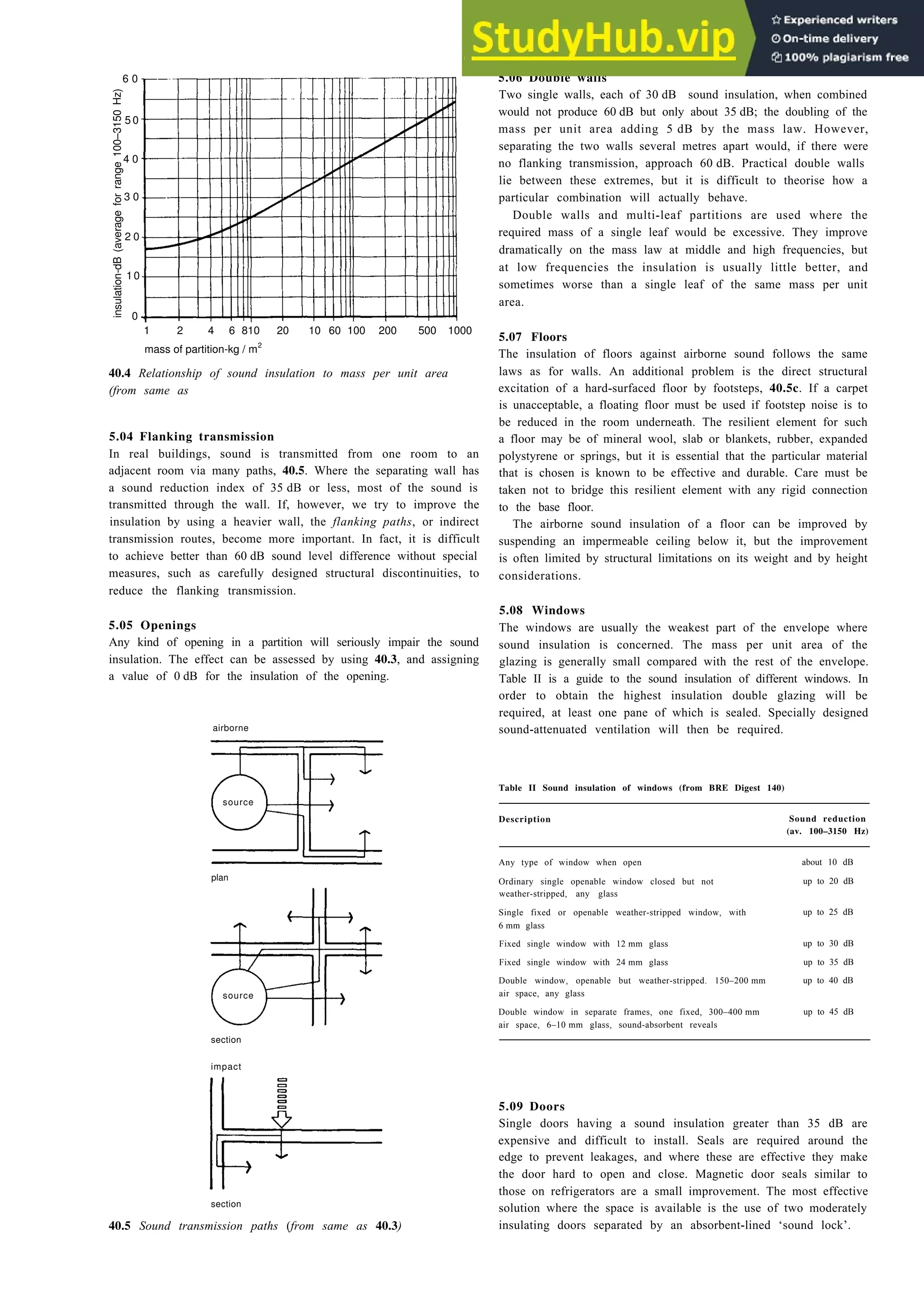
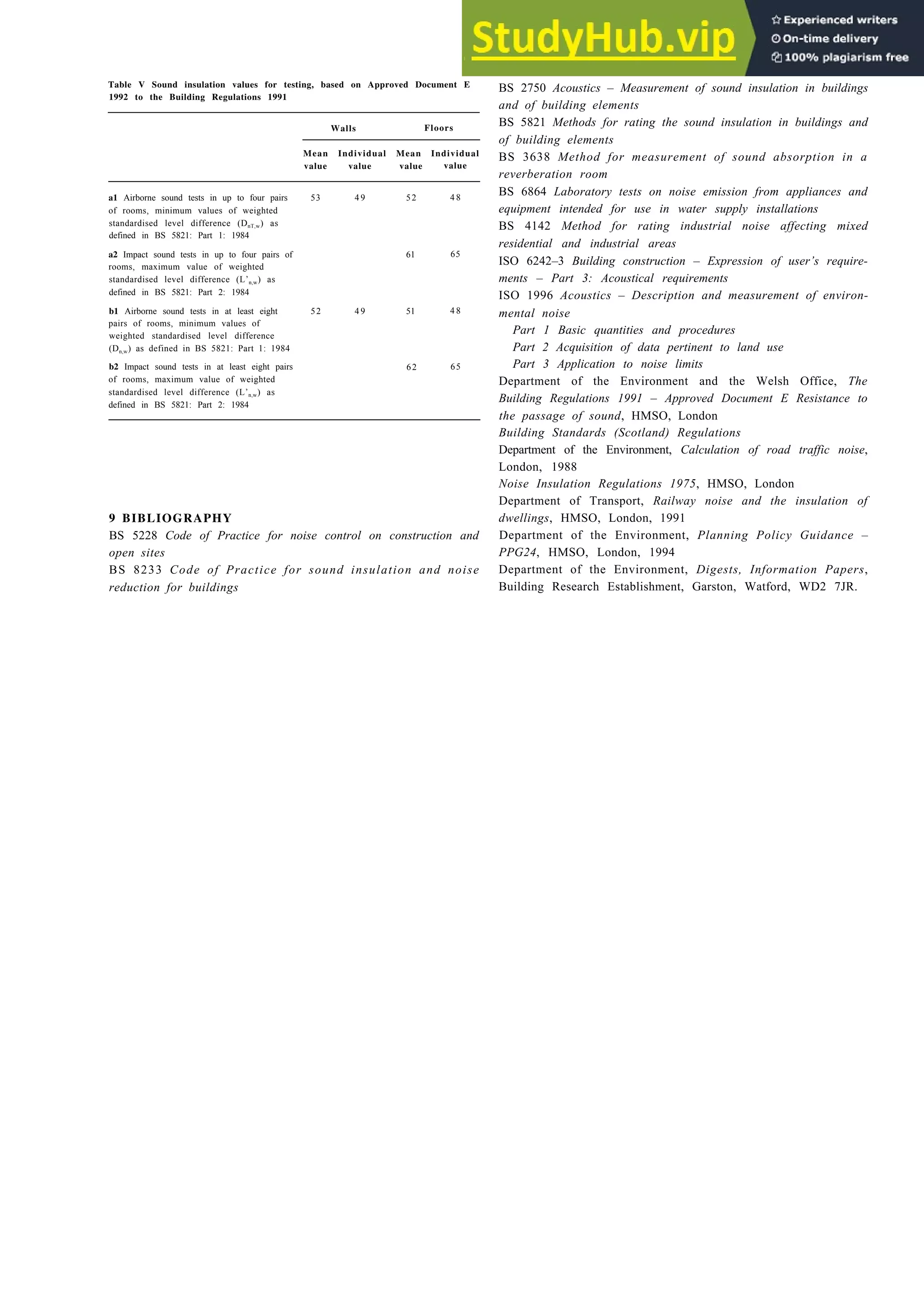
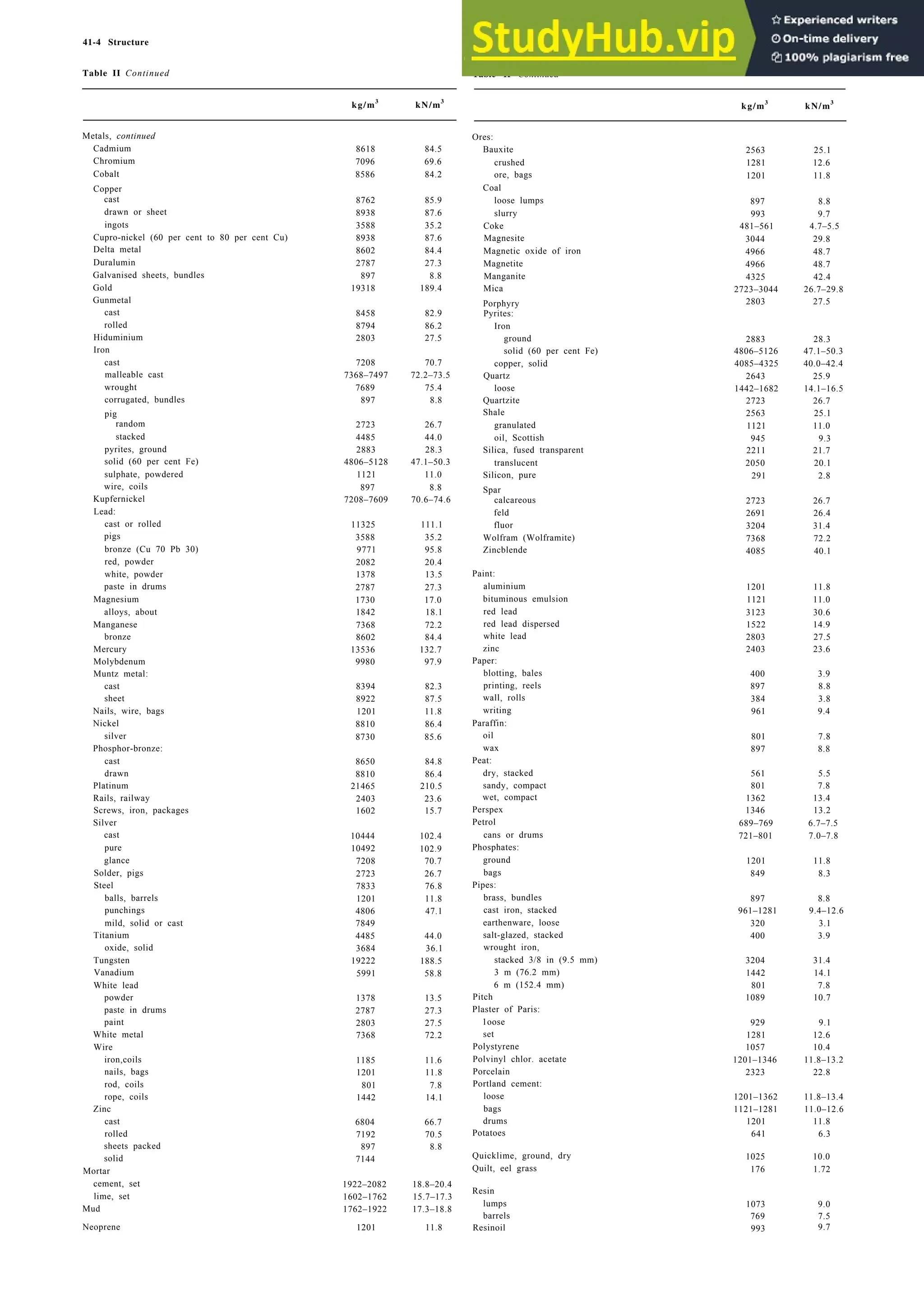
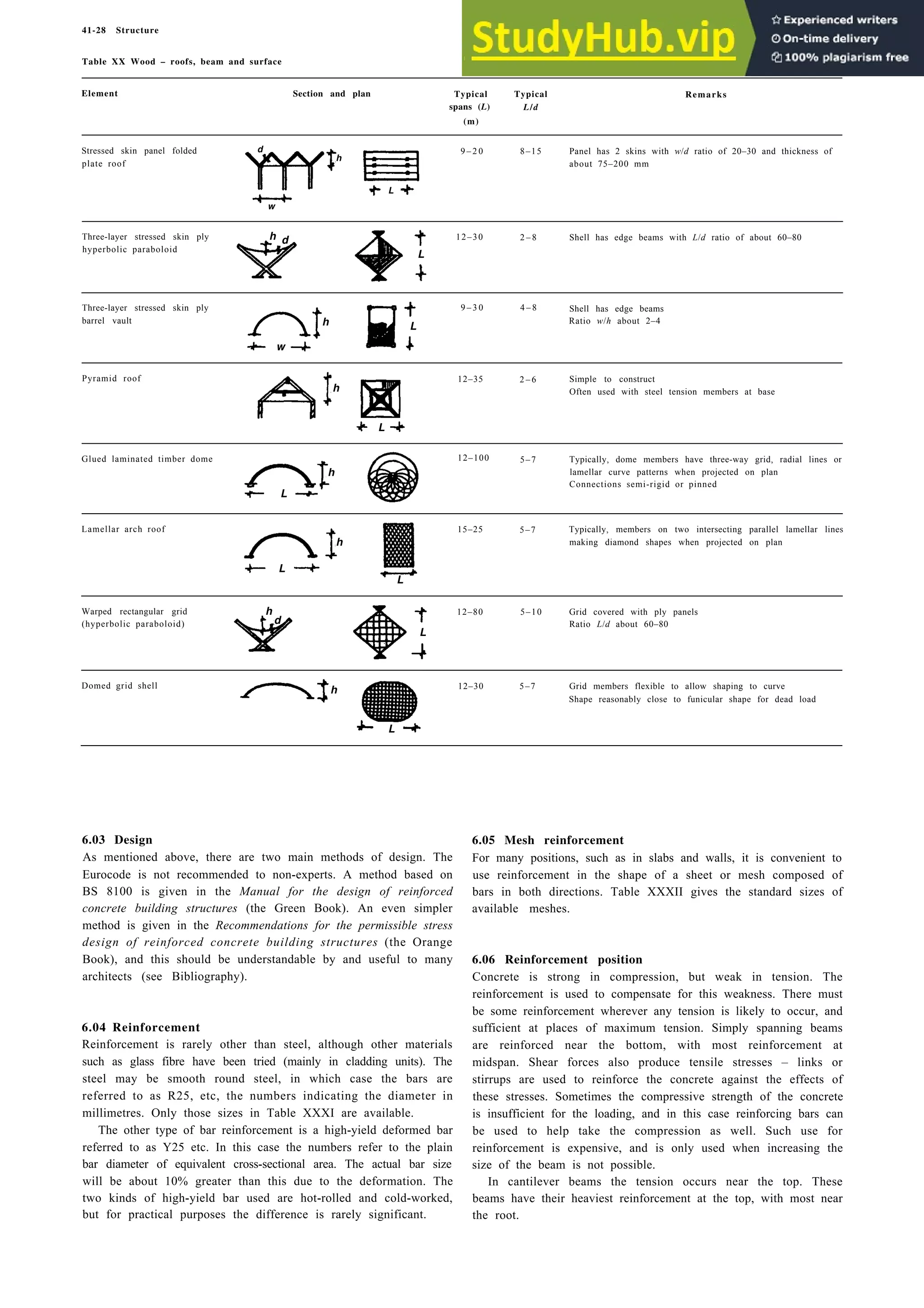
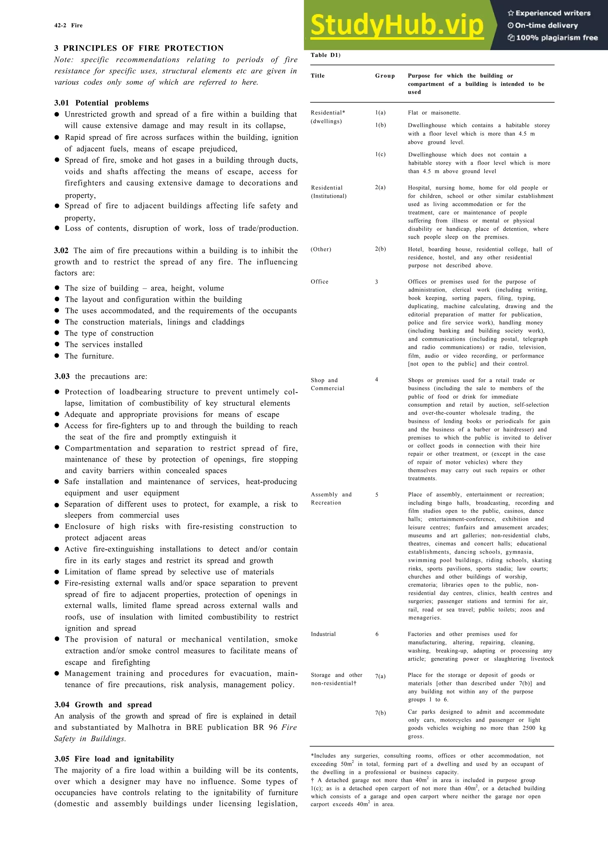
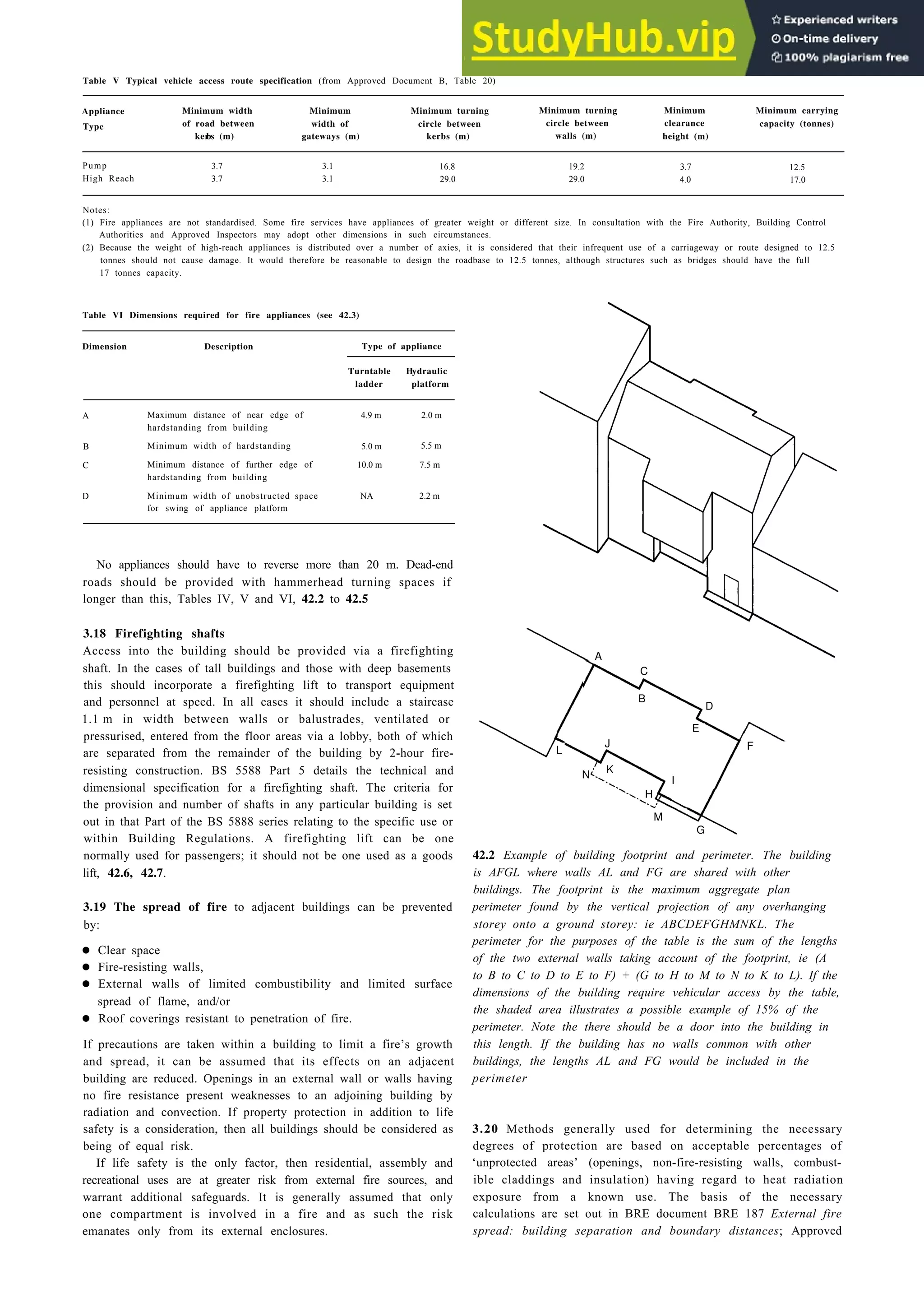
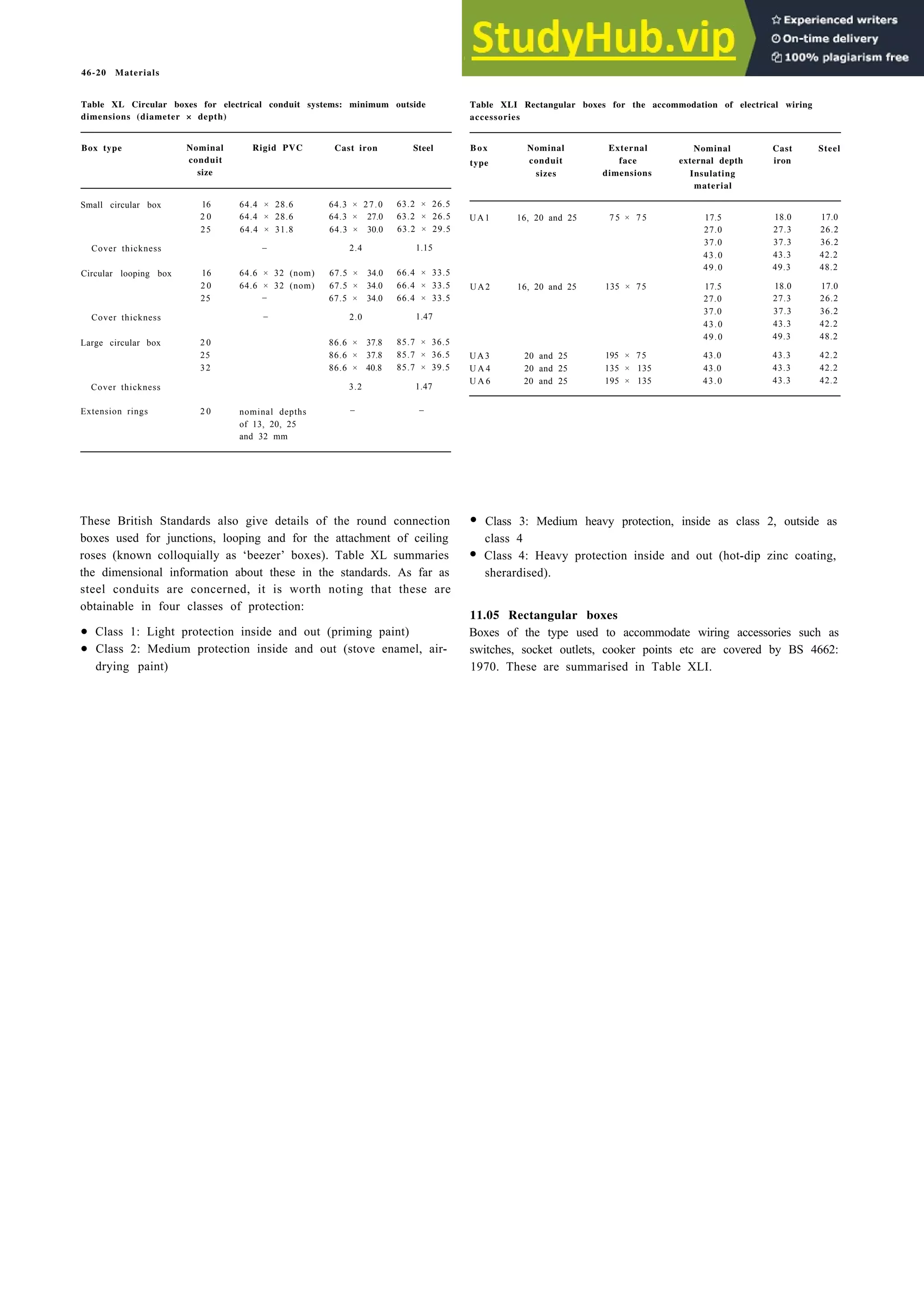
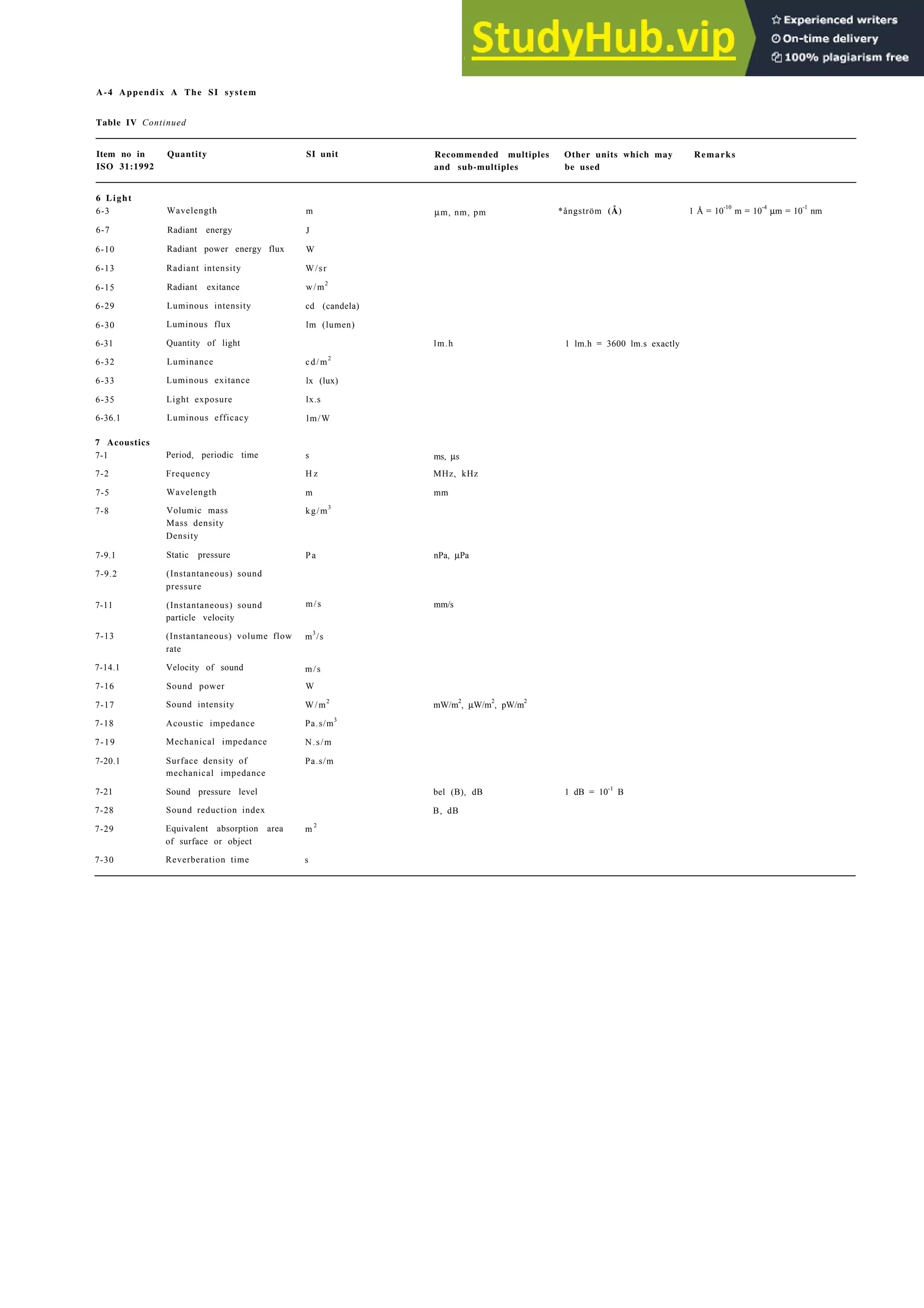
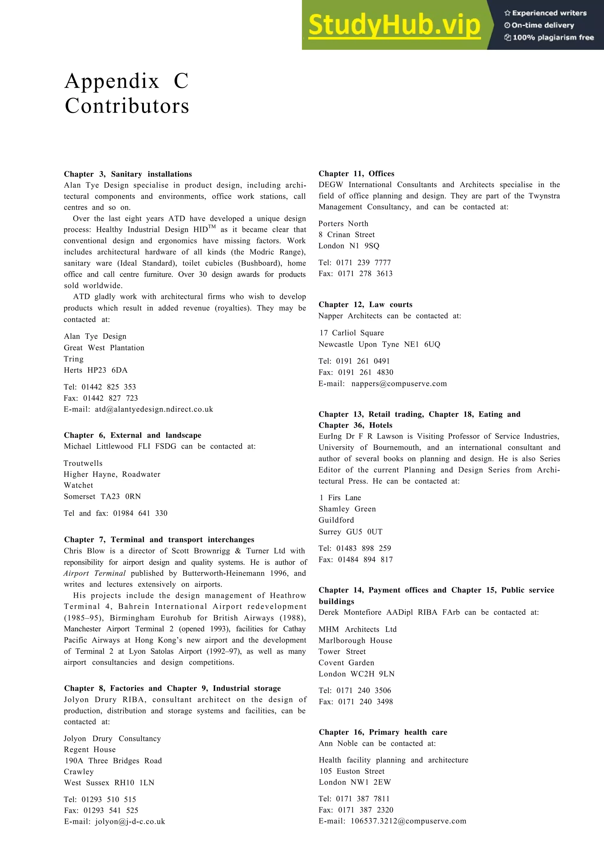
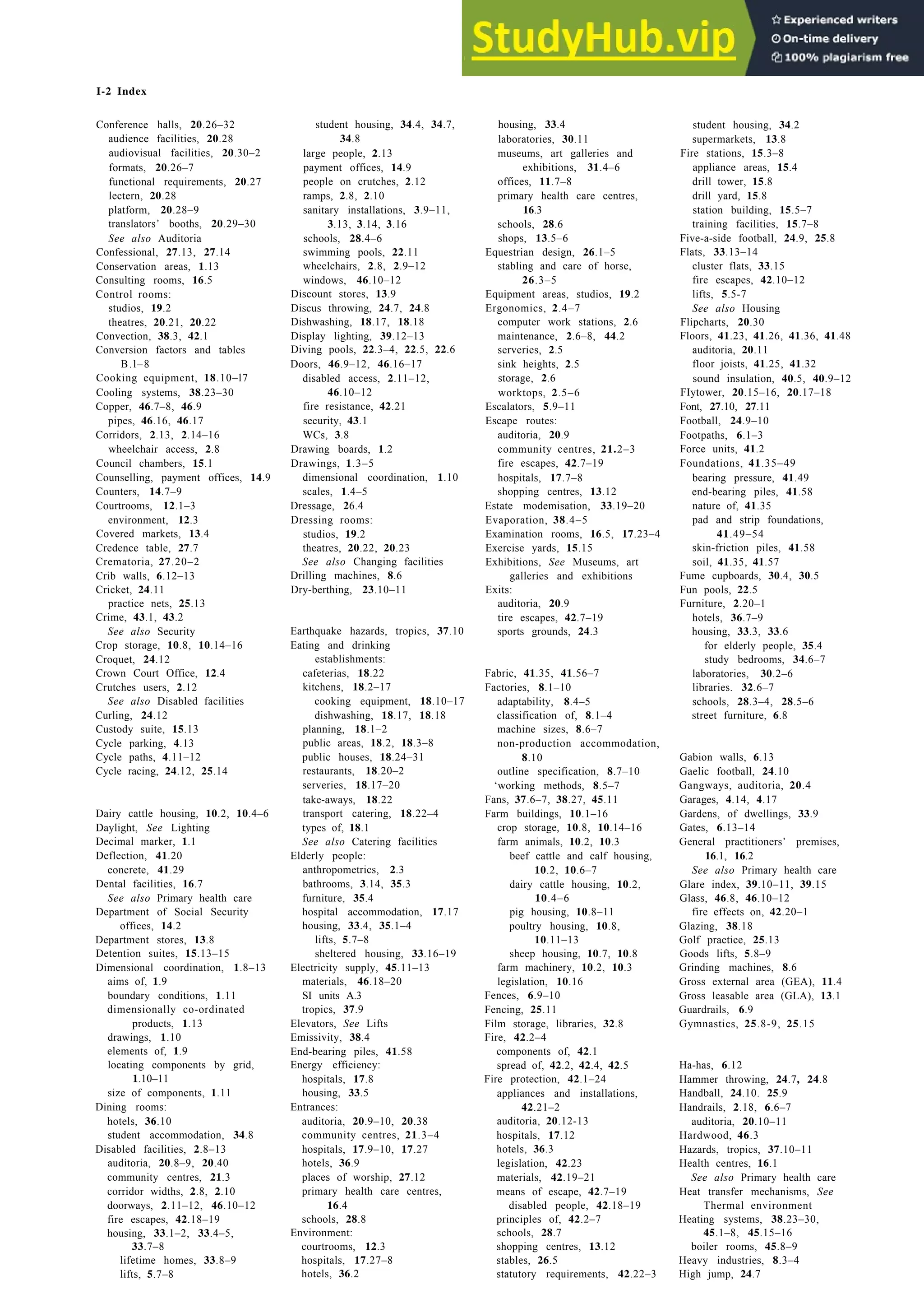
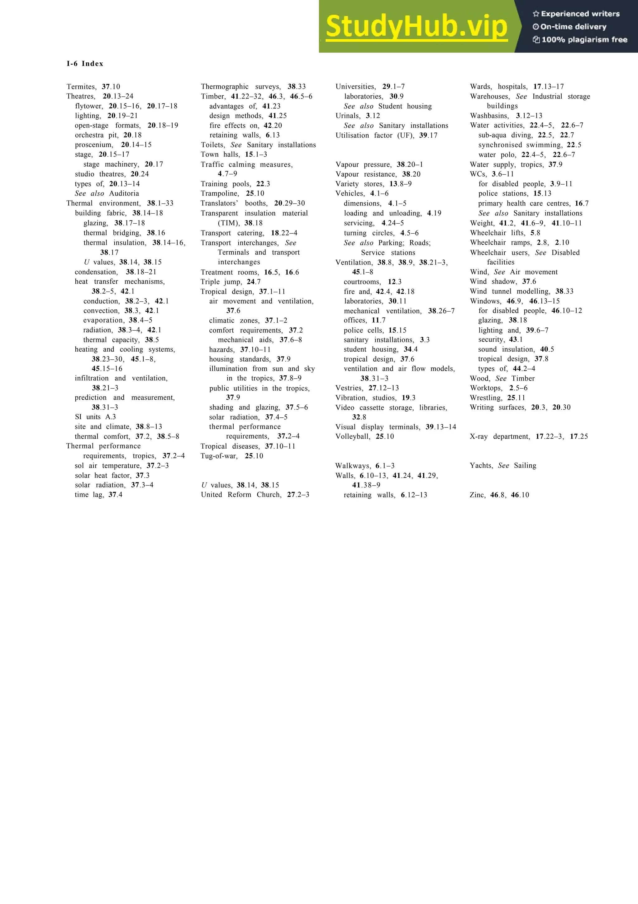
The interrelation between the amenities provided, 23.12, and the detailed breakdown of spaces and ratios is given in Table IV, and
main activities, 23.13, will control the basic layout. A marina may a checklist of accommodation and services in Table V.
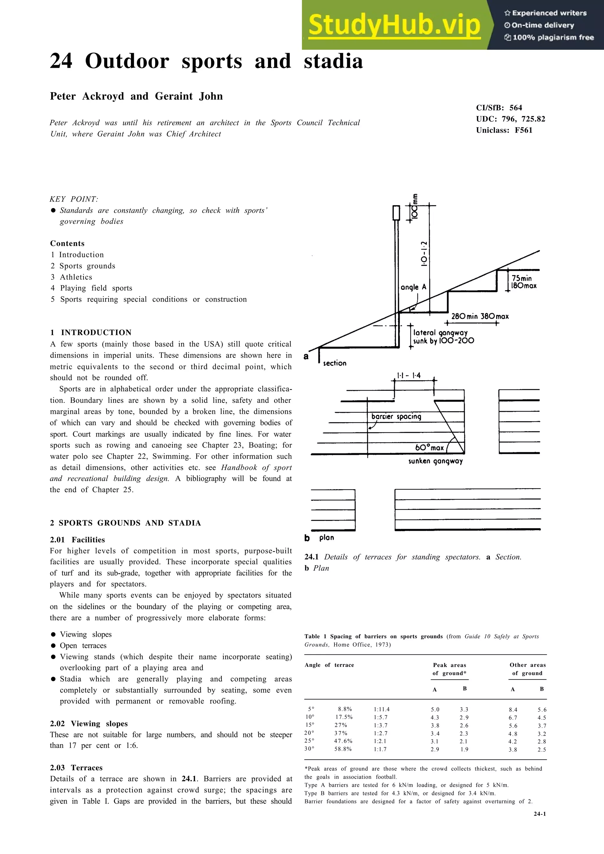
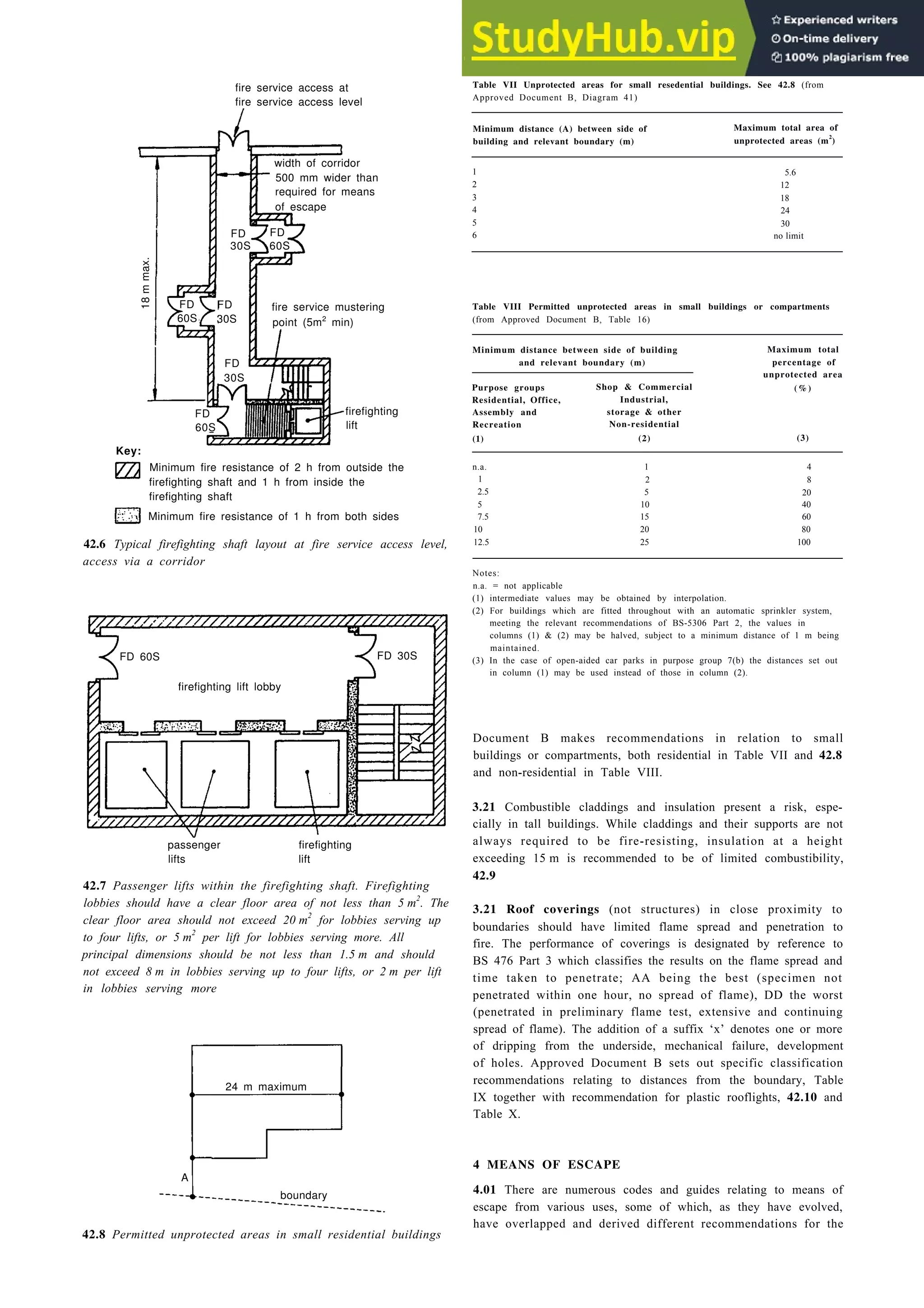
be off-shore, landlocked or anything in between, 23.14 Marina pontoons are now standard items, 23.17. They are
There are many possible layouts, but generally, equal amounts arranged to rise and fall with changes in water level. Boats are
of space are allocated to land and water, 23.15 and 23.16. A usually moored stern to the pontoon, which often has access
water 50% land 50%
%
clearances 21·0
walkways
& piers 4·0
fuelling pier 2·0
lock 3·0
moorings 20·0
50%
5·0 shops
5·0 boatbuilding & repairs
2·5 slipway / haulout
2·5 harbourmaster / customs
2·5 boat storage *
0·5 hoistwell & travelator
4·0 allied sports
0·5 bulkhead walls
2·5 leisure area
1·0 club building
2·5 service loading bay
1·0 information centre / offices
2·0 landscaping
1·0 footpaths
1·0 staff parking
2·5 workshops stores
14·0 car / trailer parking †
50·0 %
not including dual use of car parking area
† assumes 4·7 m × 2·43 m (16' × 18') bays
23.15 One allocation of on- and off-shore space assuming a 50:50 land/water split. This is
appropriate to European standards
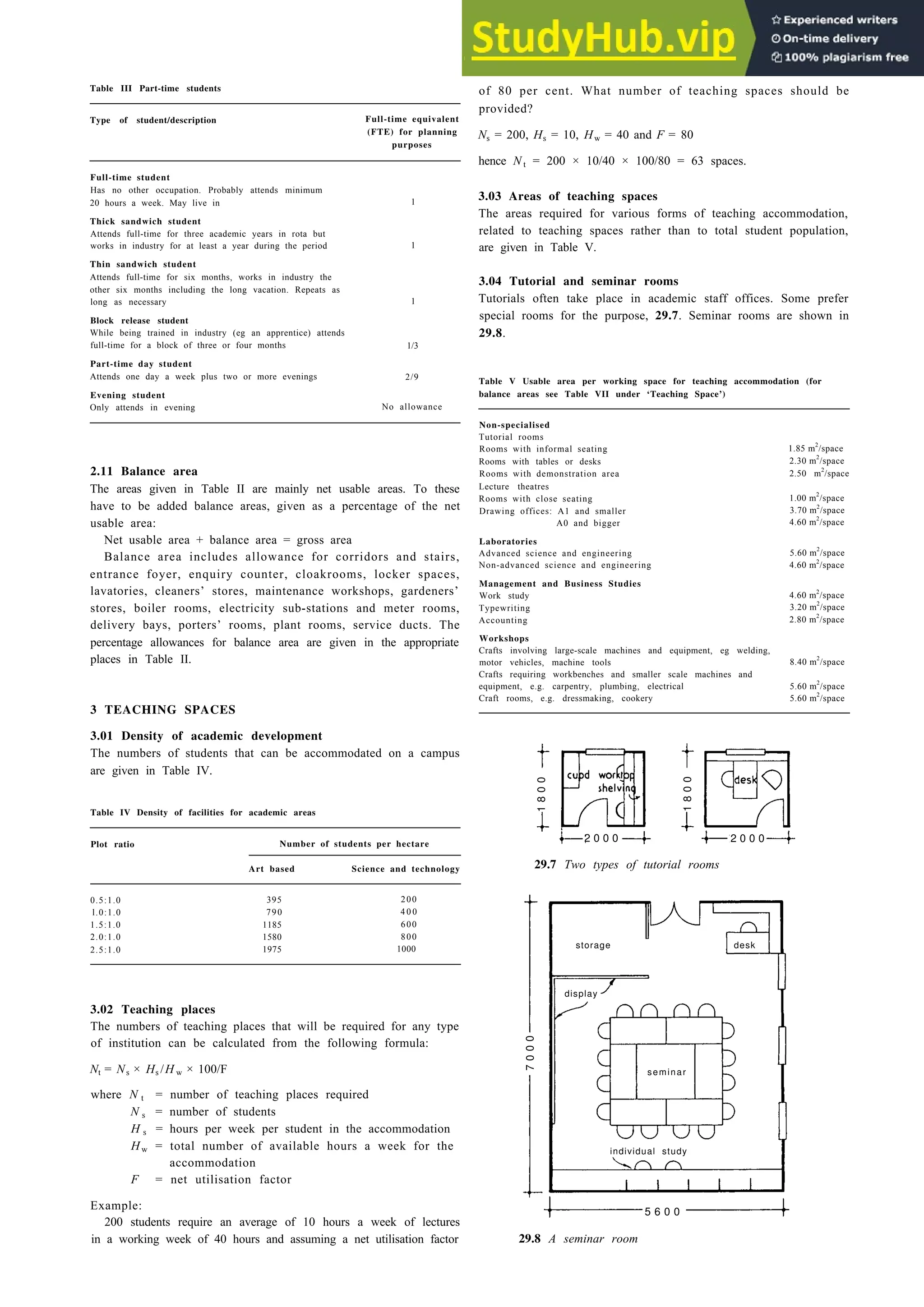
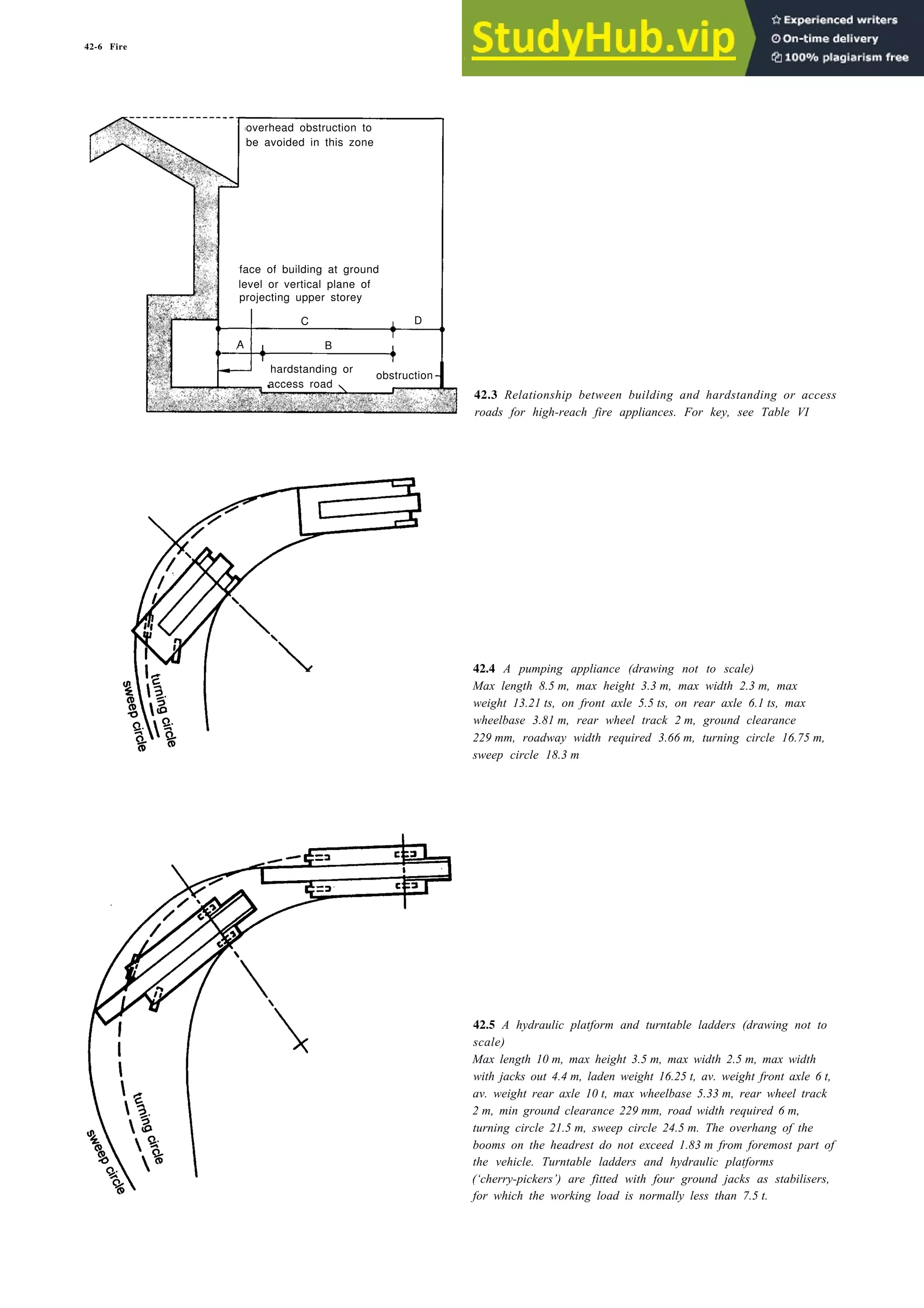
27% 28%
50%
moorings remainder
50%
clearances parking
23% 22%
water land
23.16 Principal space allocations based on the average of ten
American marinas. The difference between these figures and
those in [23.15] are mainly due to the use of a 2.7 × 5.8 m
parking bay
Table IV Spatial requirements and likely size ranges
Min. Max.
Land-to-water ratio 1:1 2:1
Density of boats/hectare (wet moorings) 62 162
Density of boats/hectare on hardstanding 25 75
Car-to-boat ratio 1:1 1:5:1
Density of cars/hectare (2.4 × 5.0 bays) 350 520
Ranges of boat length 4.8–13.7 m 4.3–21.3 m
Ranges of boat beam 1.8–4.3 m 1.5–6.0 m
Ranges of boat draught: inboard 0.64–1.27 m 0.48–1.65 m
outboard 0.30–0.56 m 0.20–0.64 m
sailing boats 1.14–1.77 m 1.00–2.16 m
Average boat length 5.5 m 9 m
Percentage total parking area to total water area 20% 50%
People-to-boats ratio 1.5:1 3:1
People-to-cars ratio 1:1 4.5:1
Cars-to-boats ratio 1:2 2:1
3050
walkway 2440 detachable
removable
services
deck sections
continuous
100 × 150 fender
protection skirt
through
rigid foam flotation bolts anchor
billets
diagonal bracing
foam frame
pile
23.17a Construction detail of floating pier, section A–A
23.17b Detail of anchor pile
top 3280
location of
mooring
3050 hardware
2440 2300
1830
1220
1370
610
0.0
finger pier
1830
securing
610 guide
0.0
1220
hinge
2440](https://image.slidesharecdn.com/architectureebookmetrichandbookplanninganddesigndata-230807180049-33007df6/75/Architecture-Ebook-Metric-Handbook-Planning-and-Design-Data-pdf-388-2048.jpg)

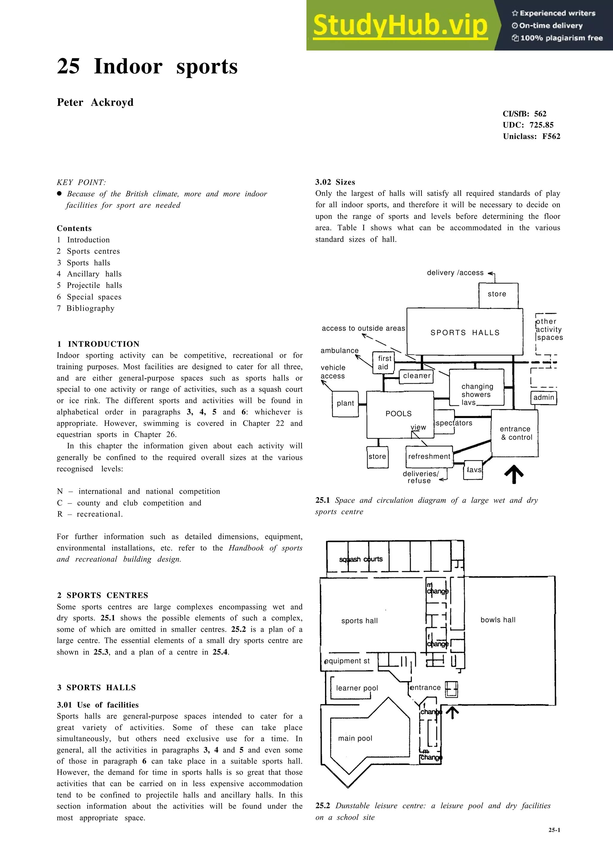
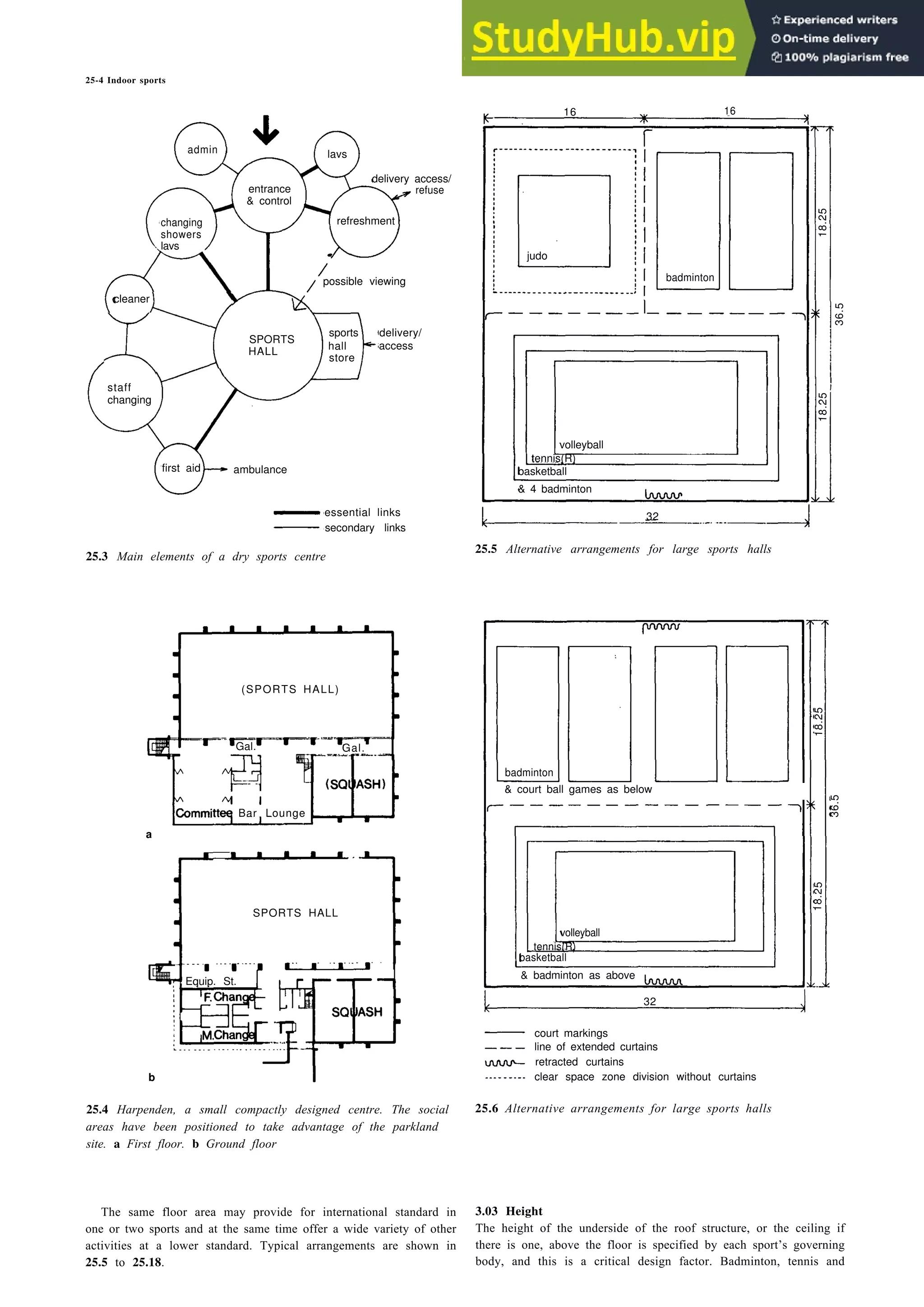
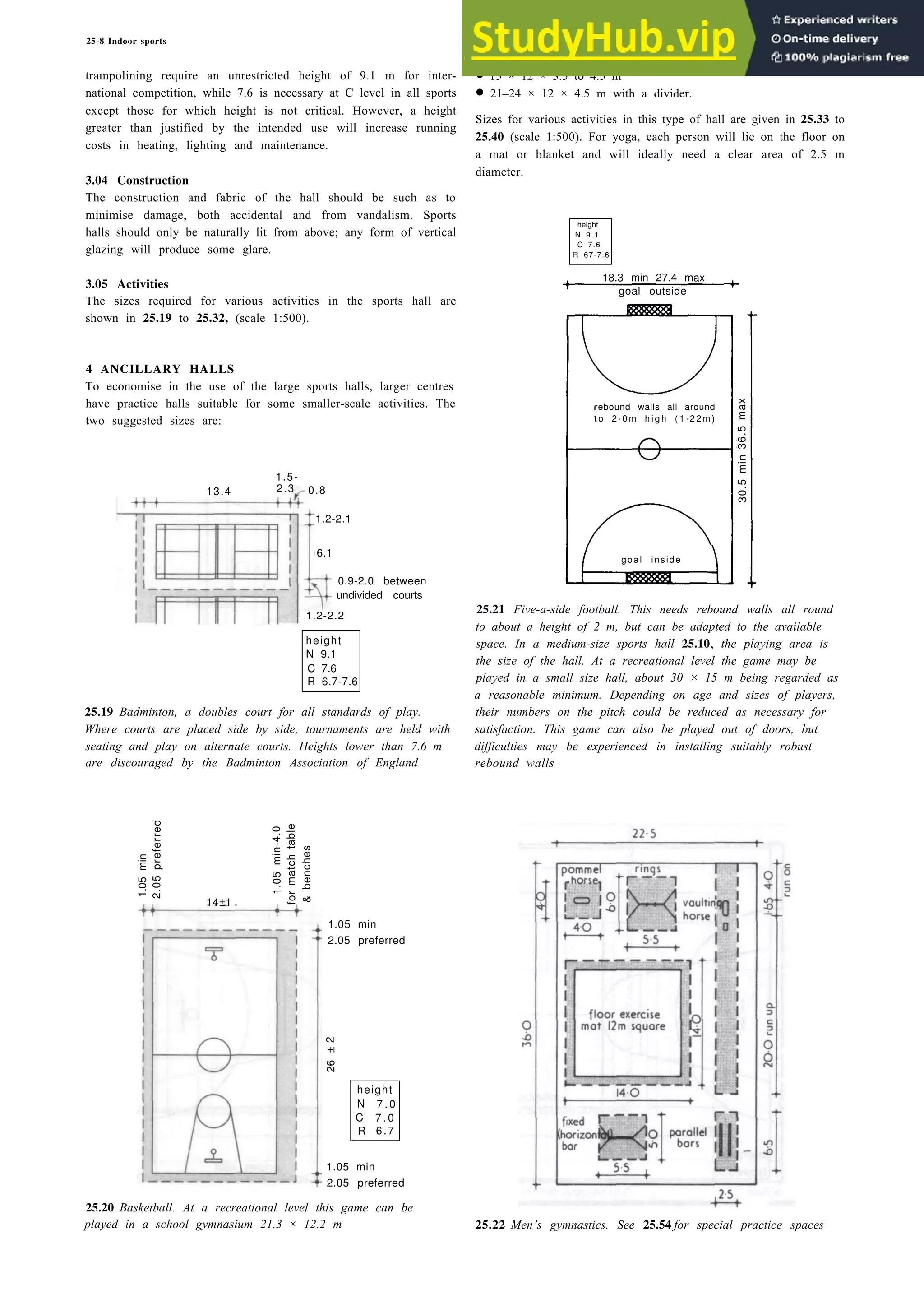
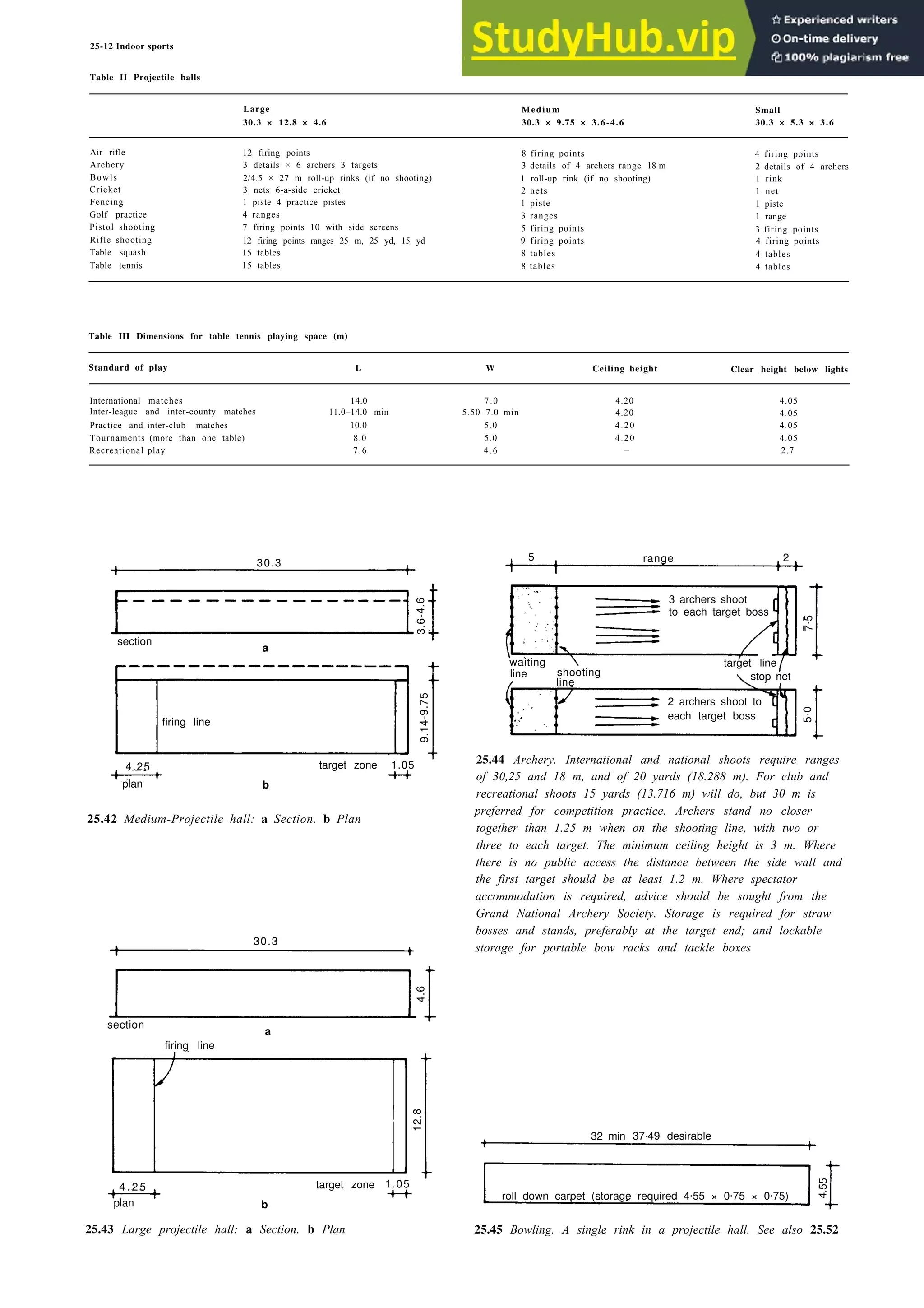
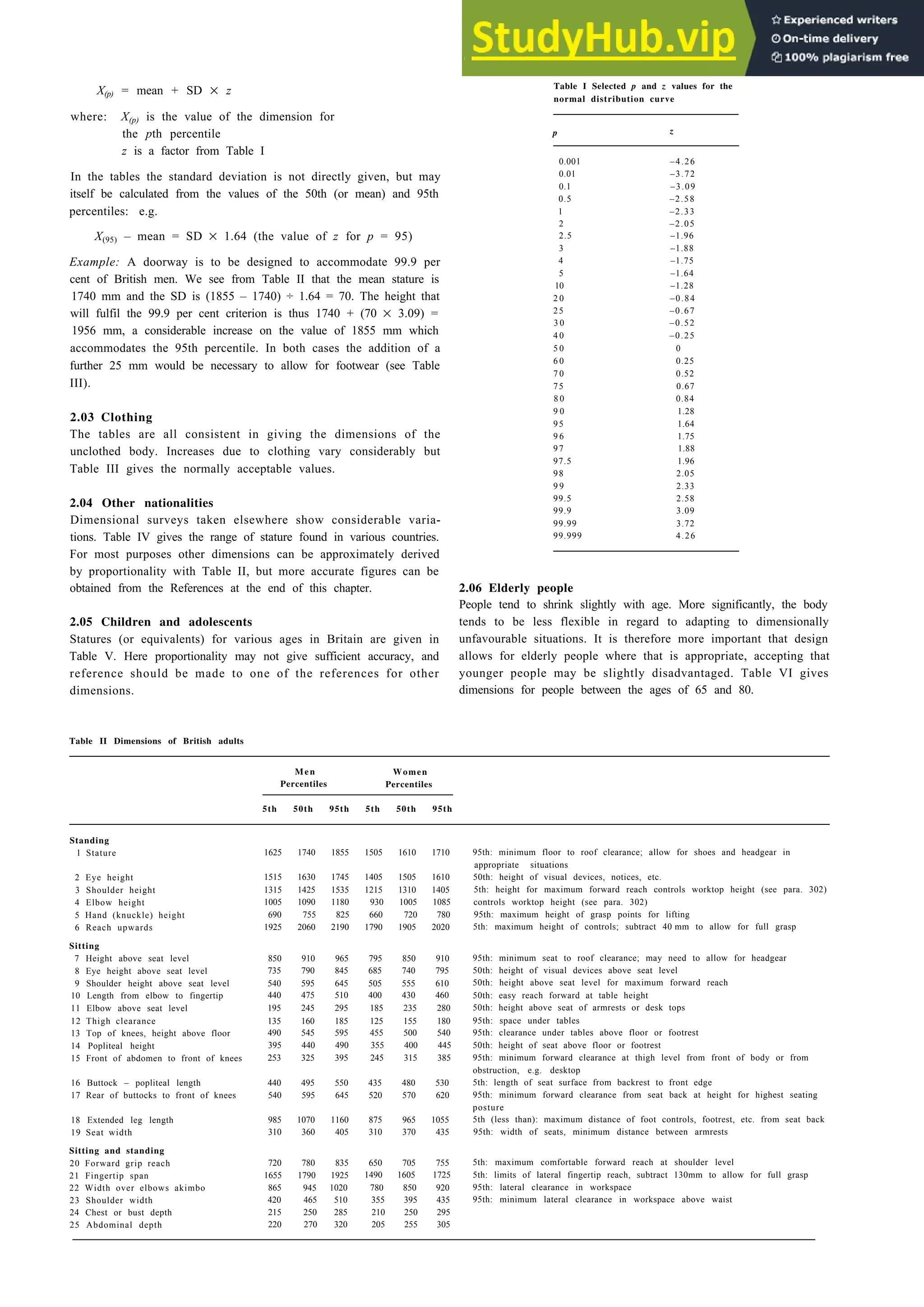
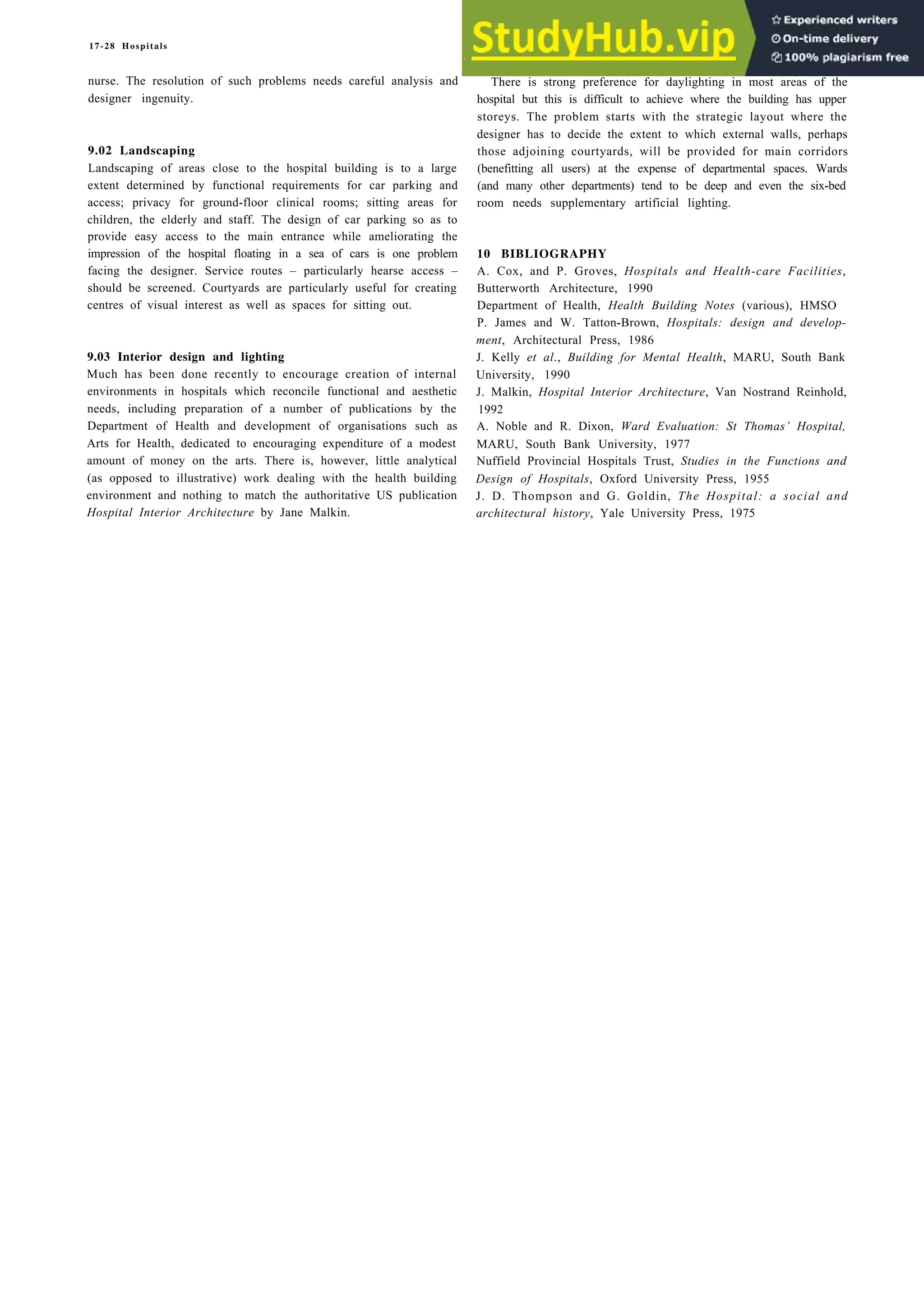
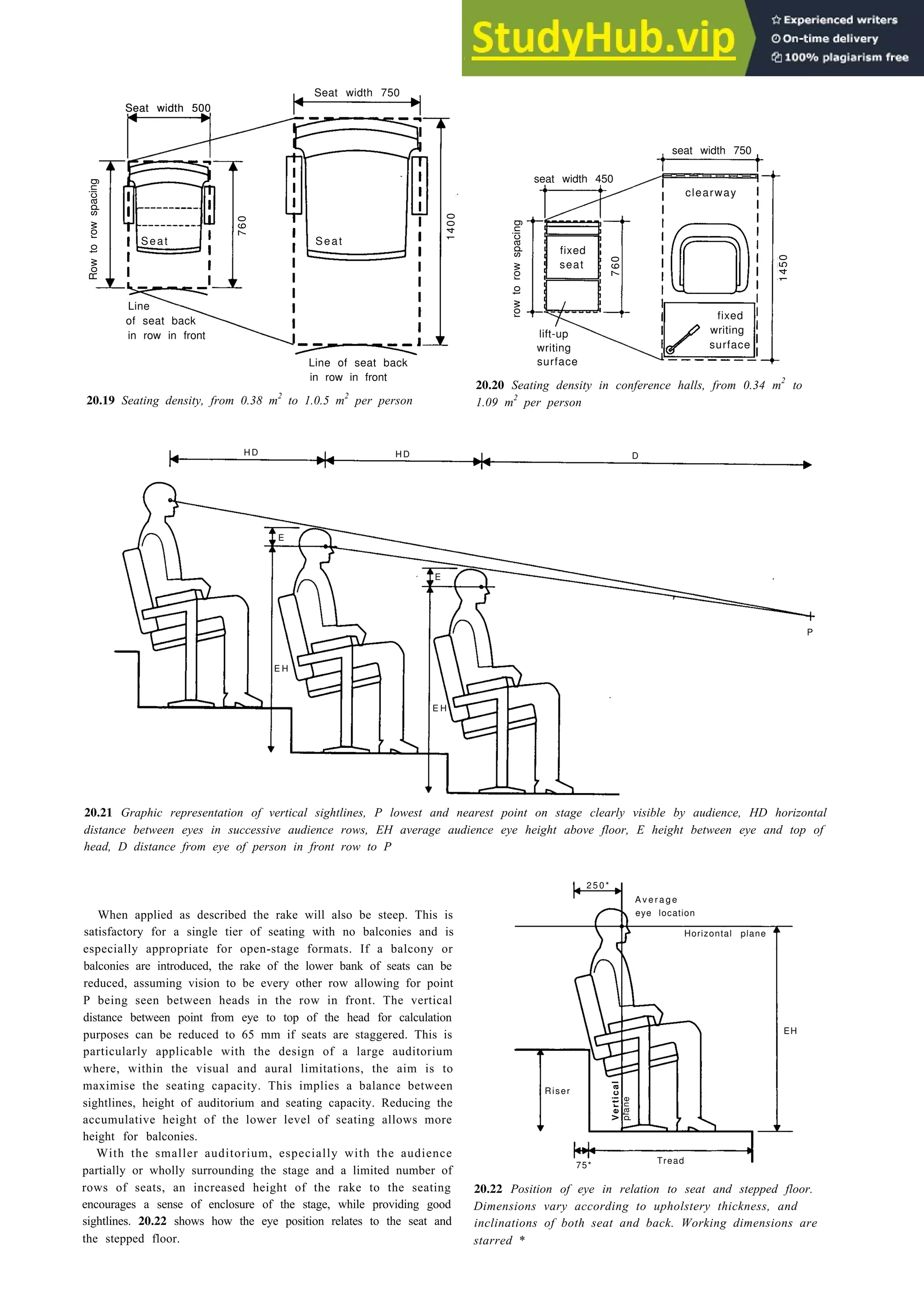
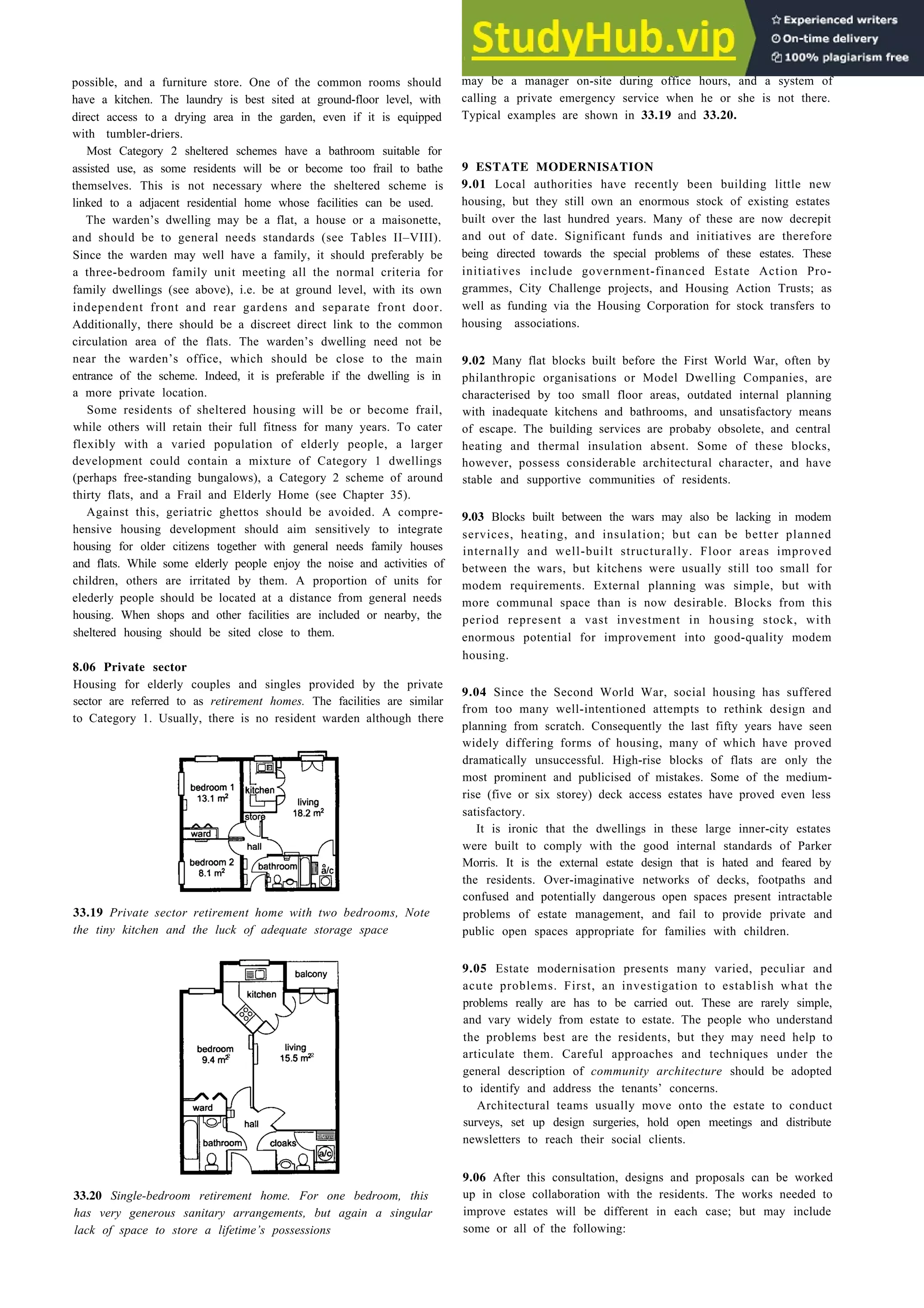
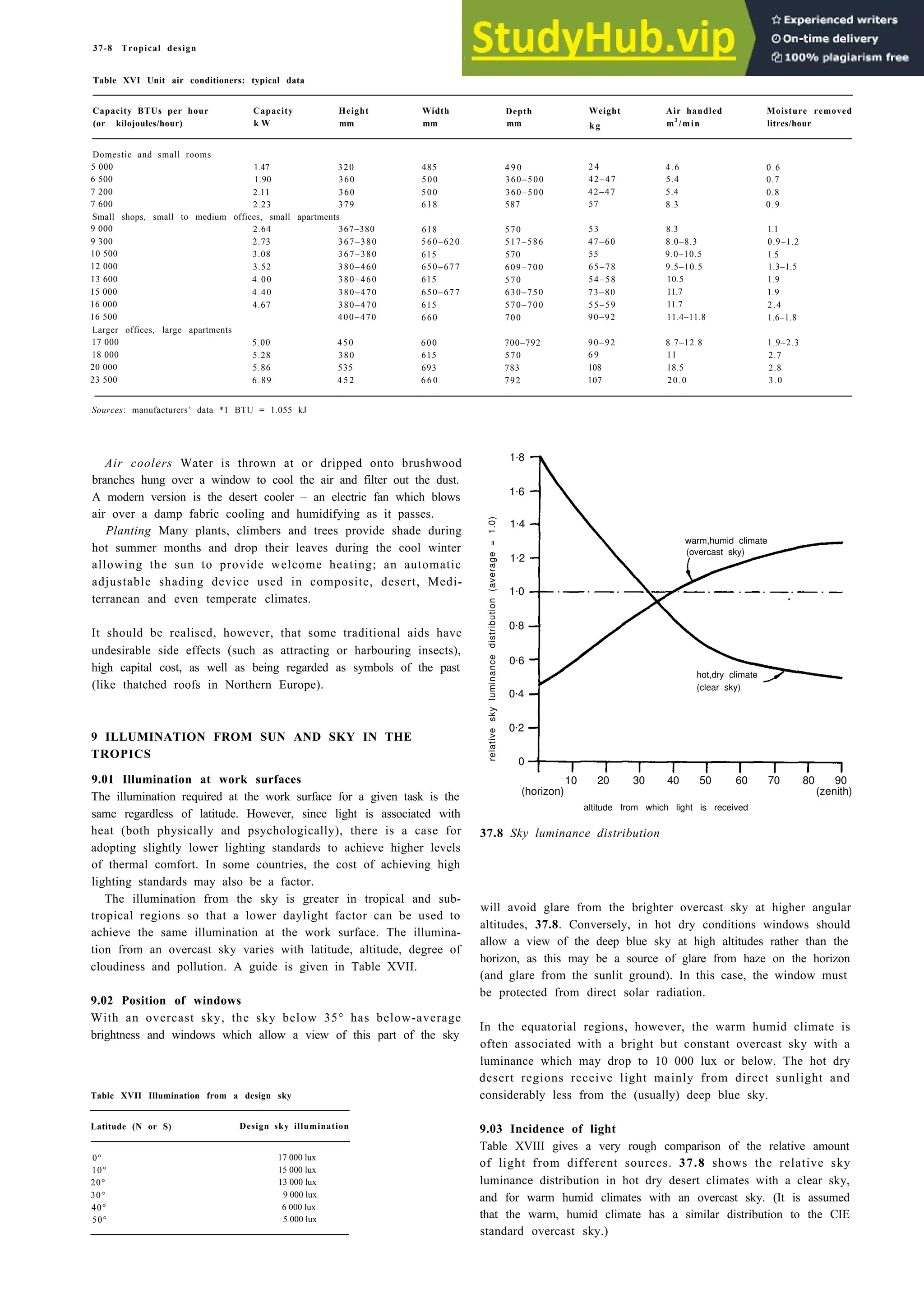
![25-14 Indoor sports
bend
length
B
(may
be
banked)
overall
width
W
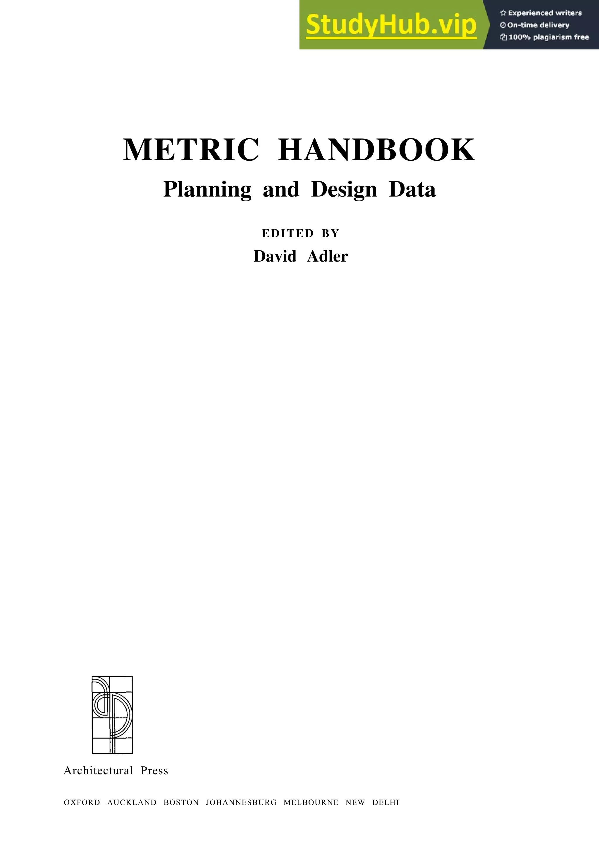
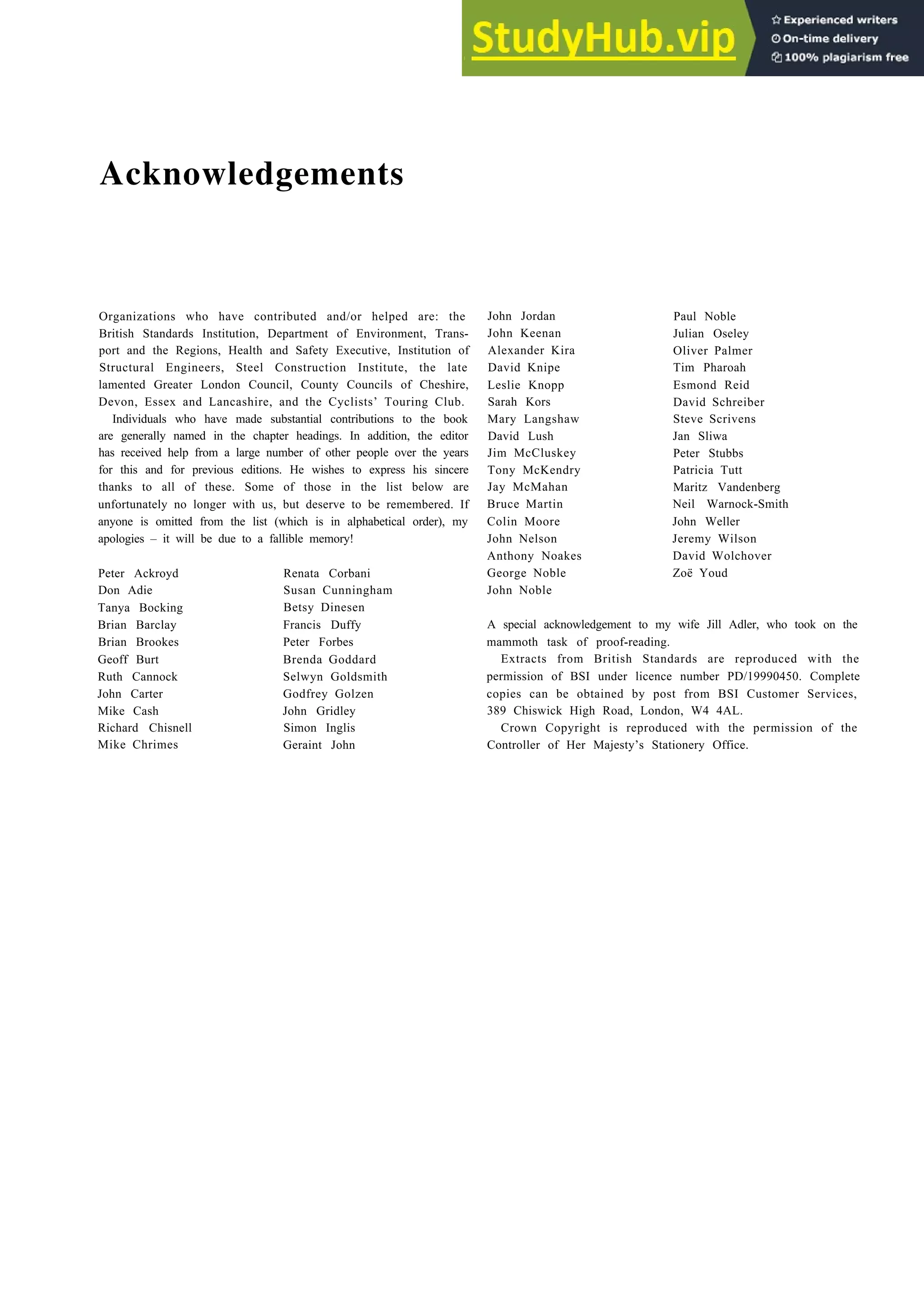
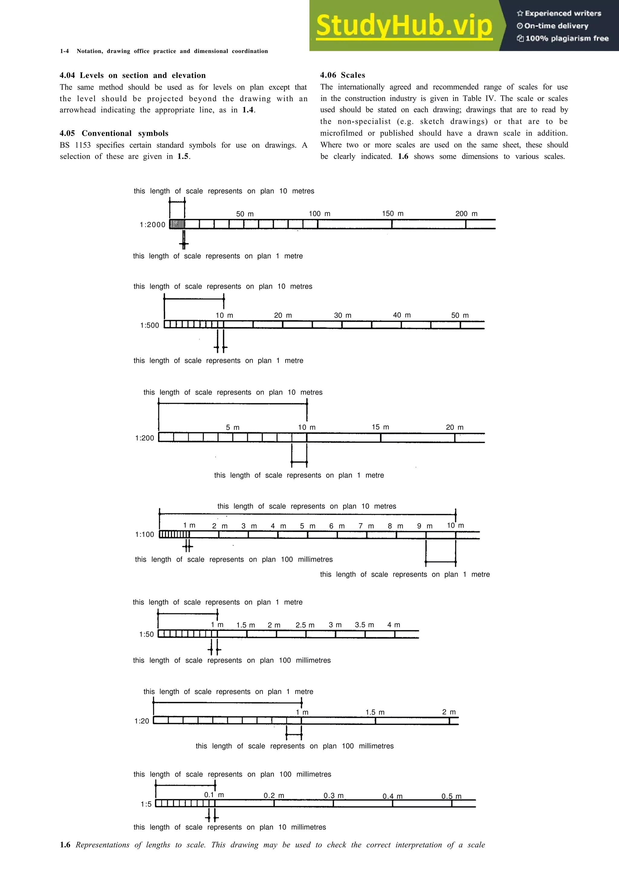
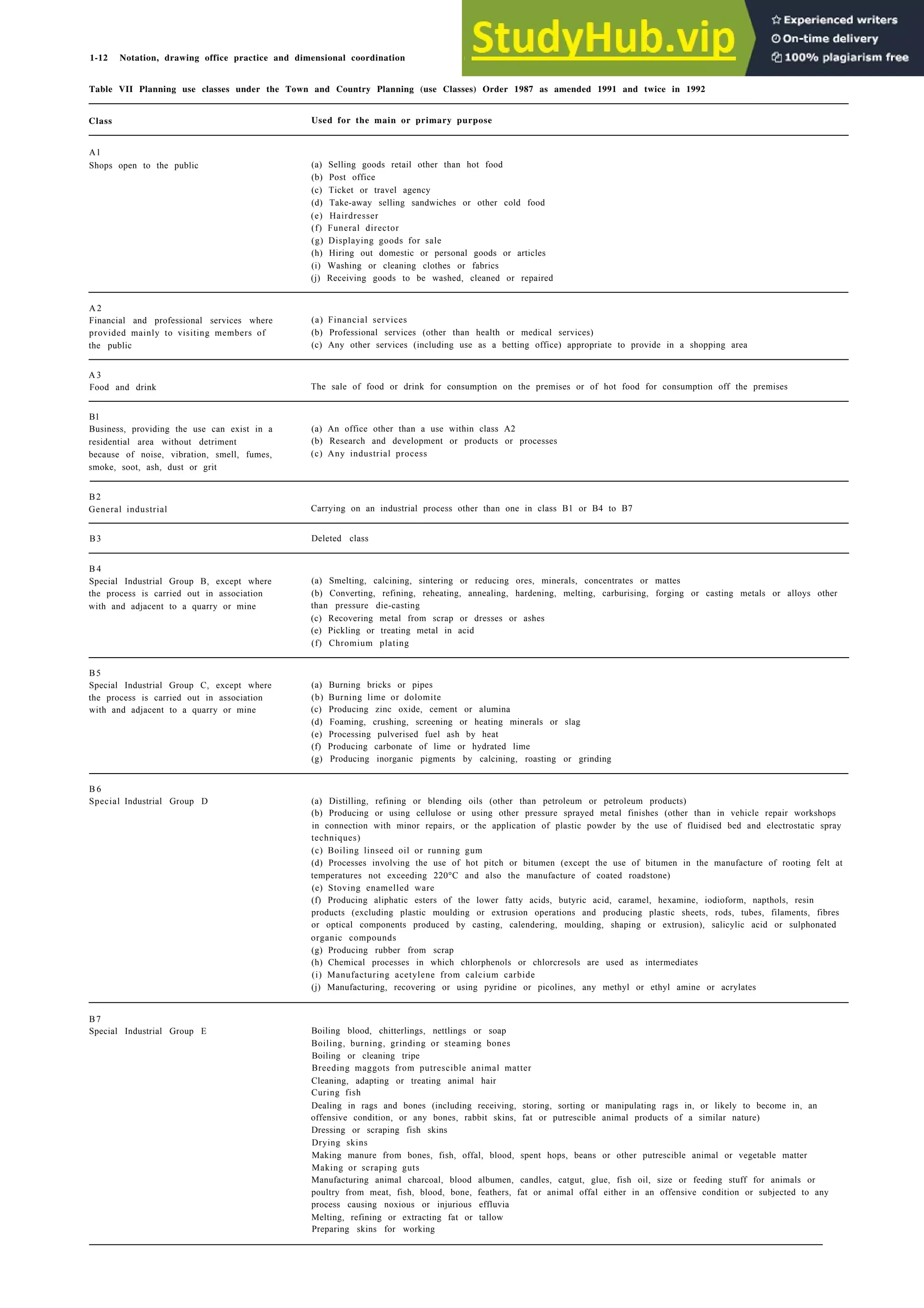
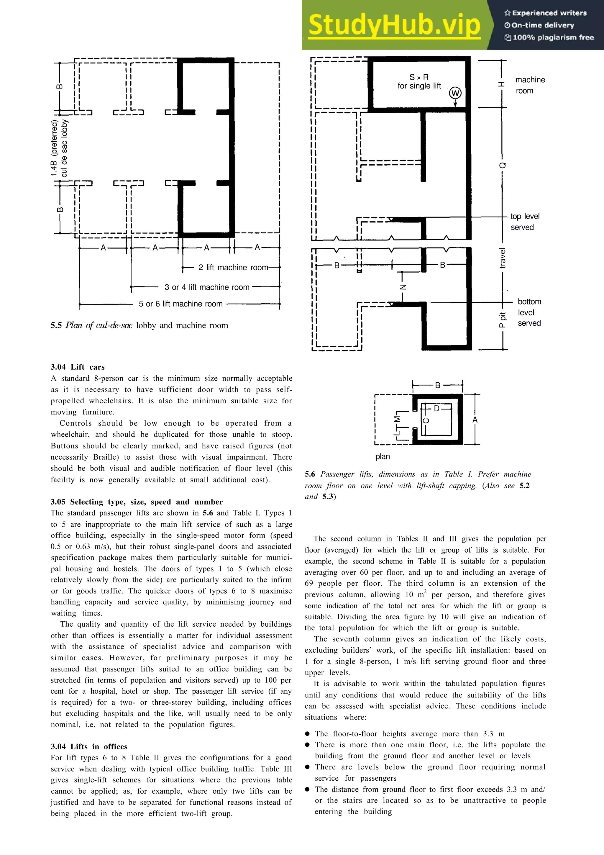
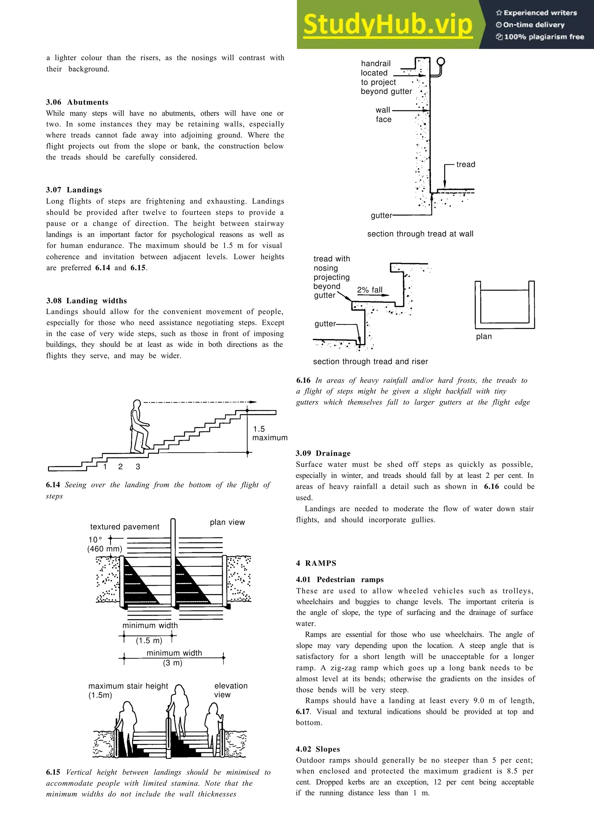
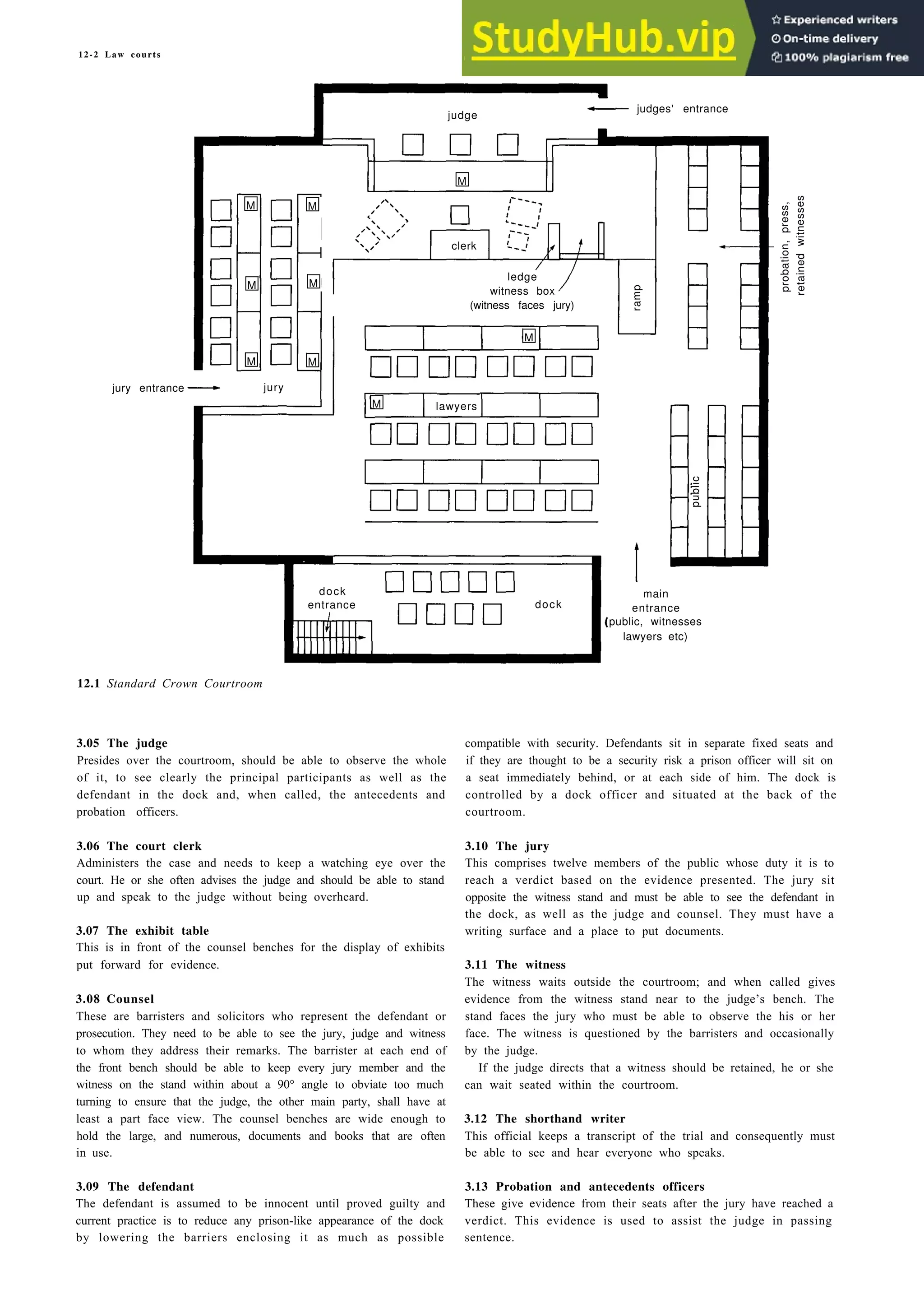
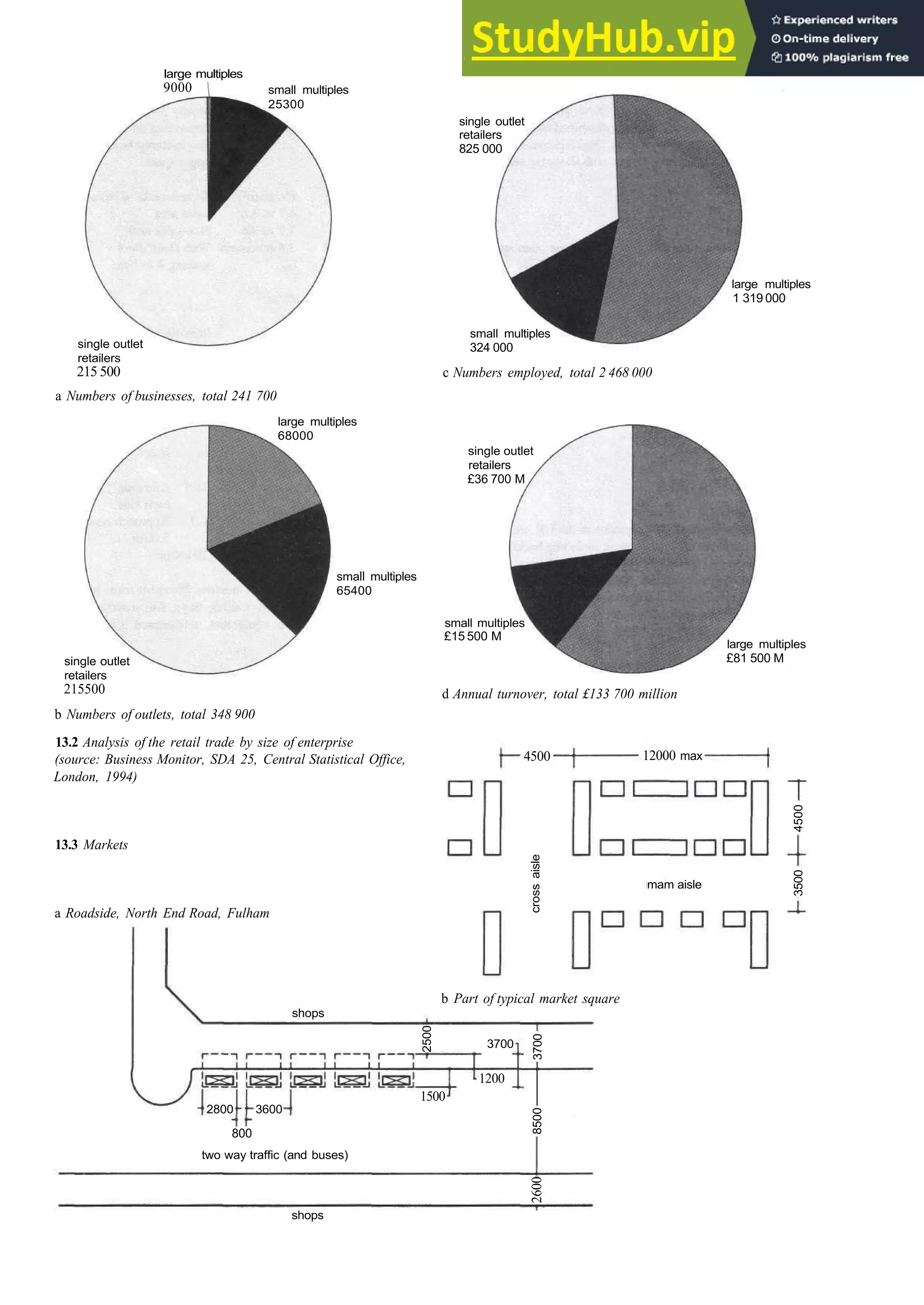
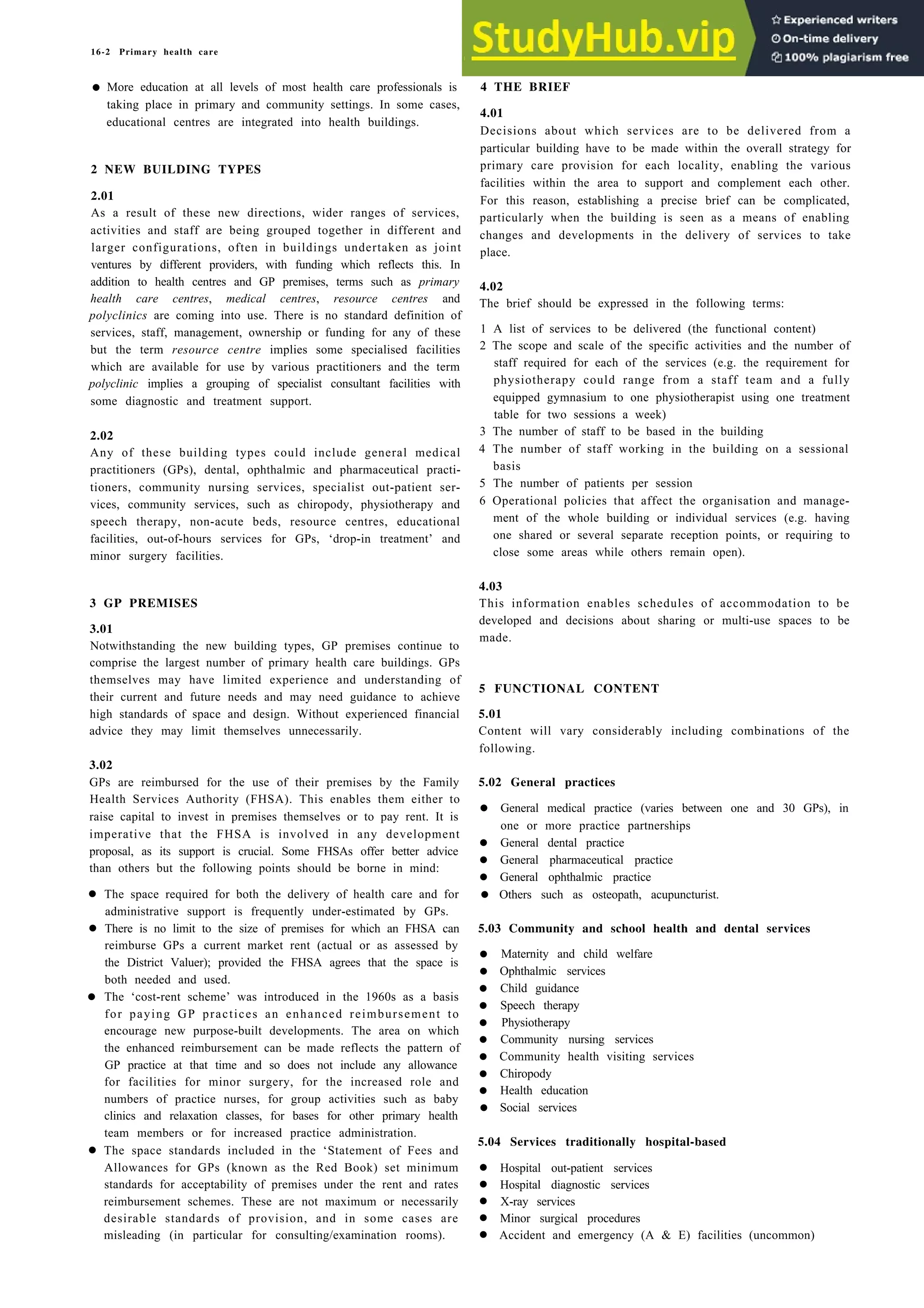
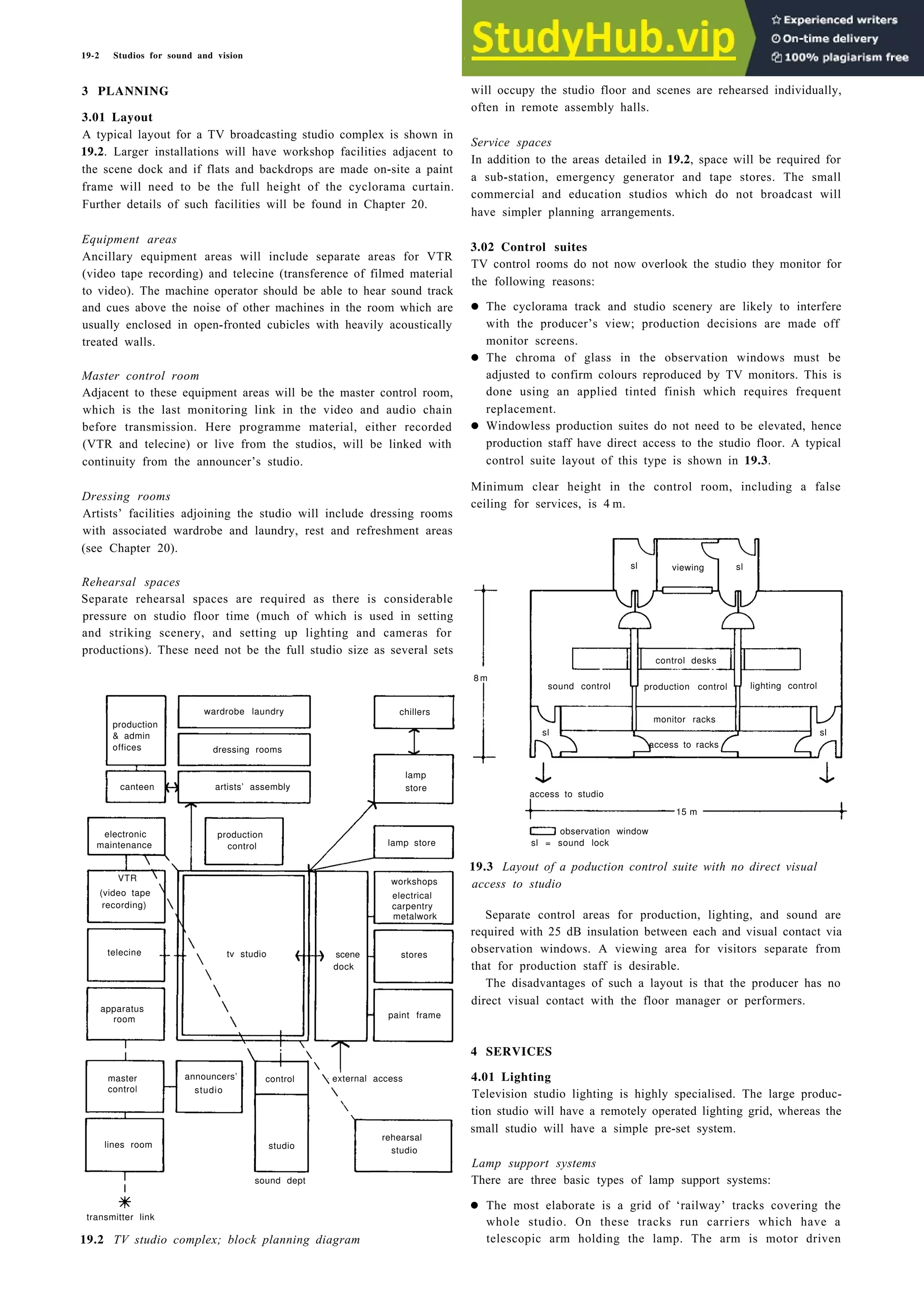
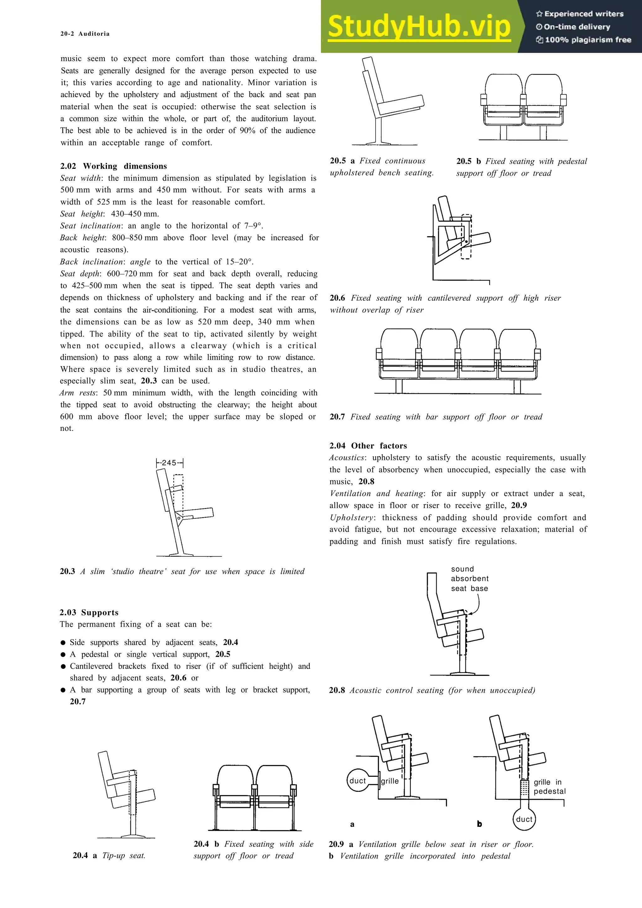
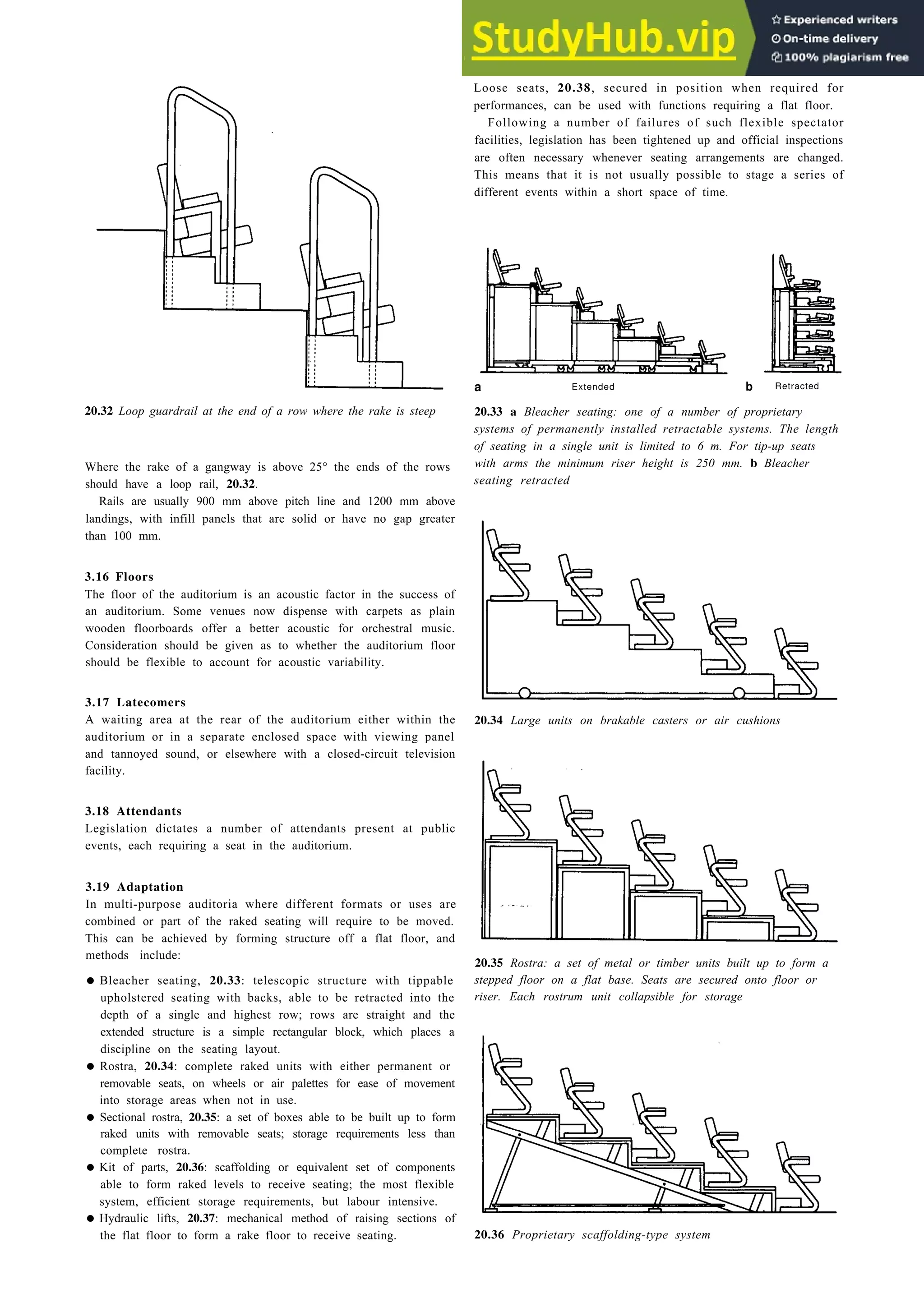
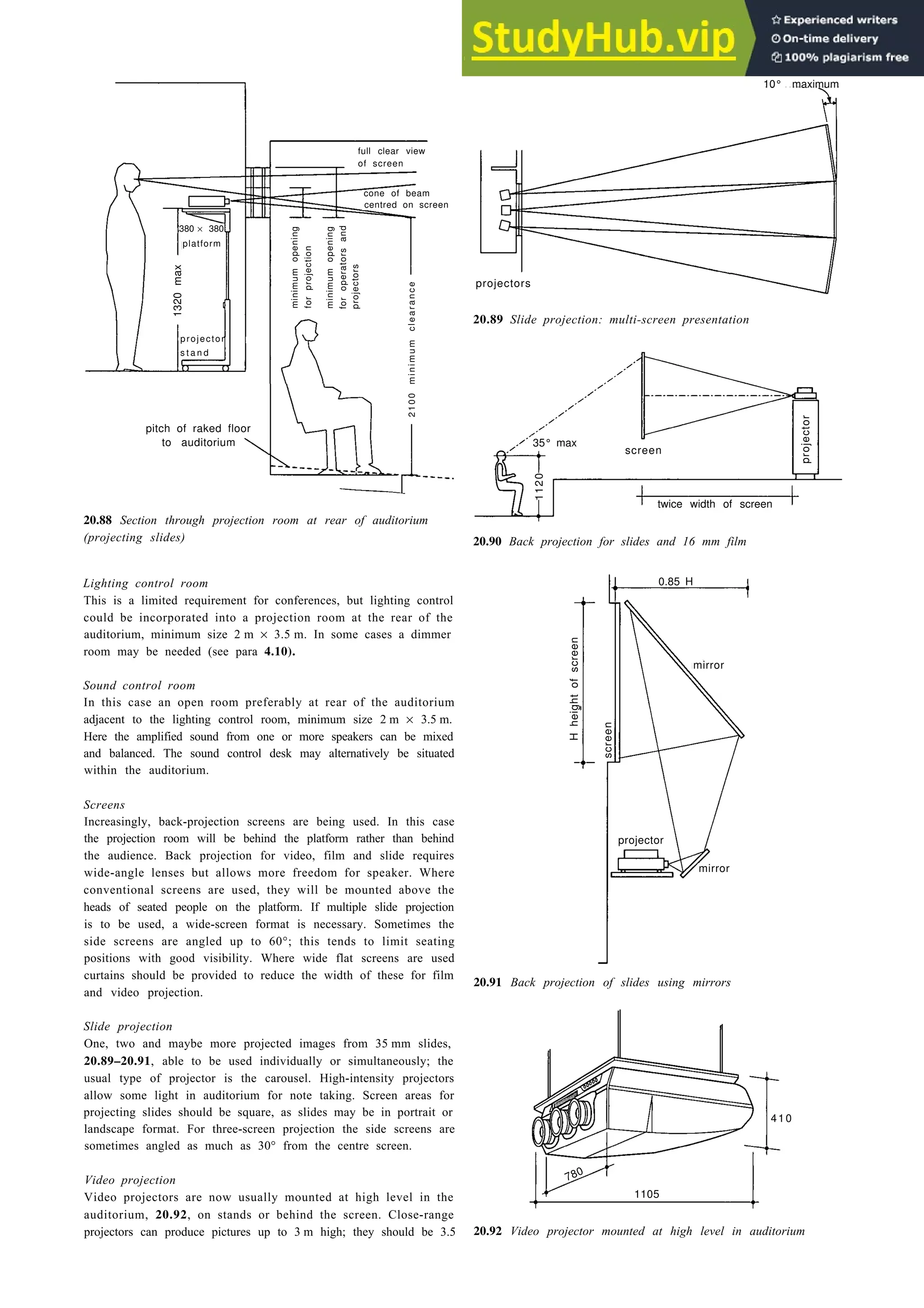
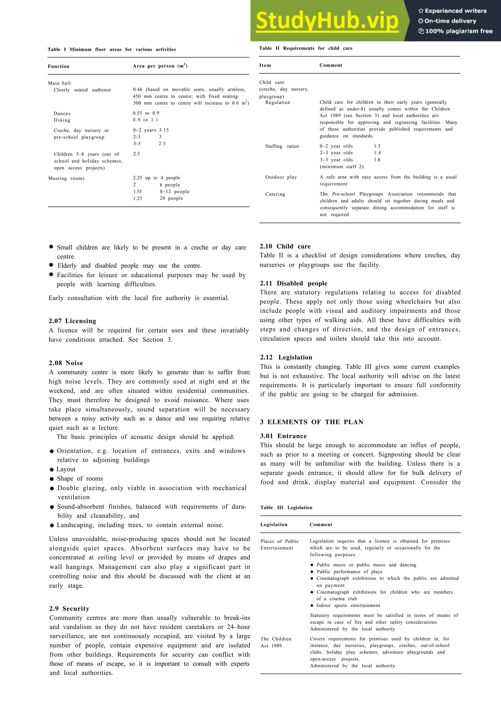
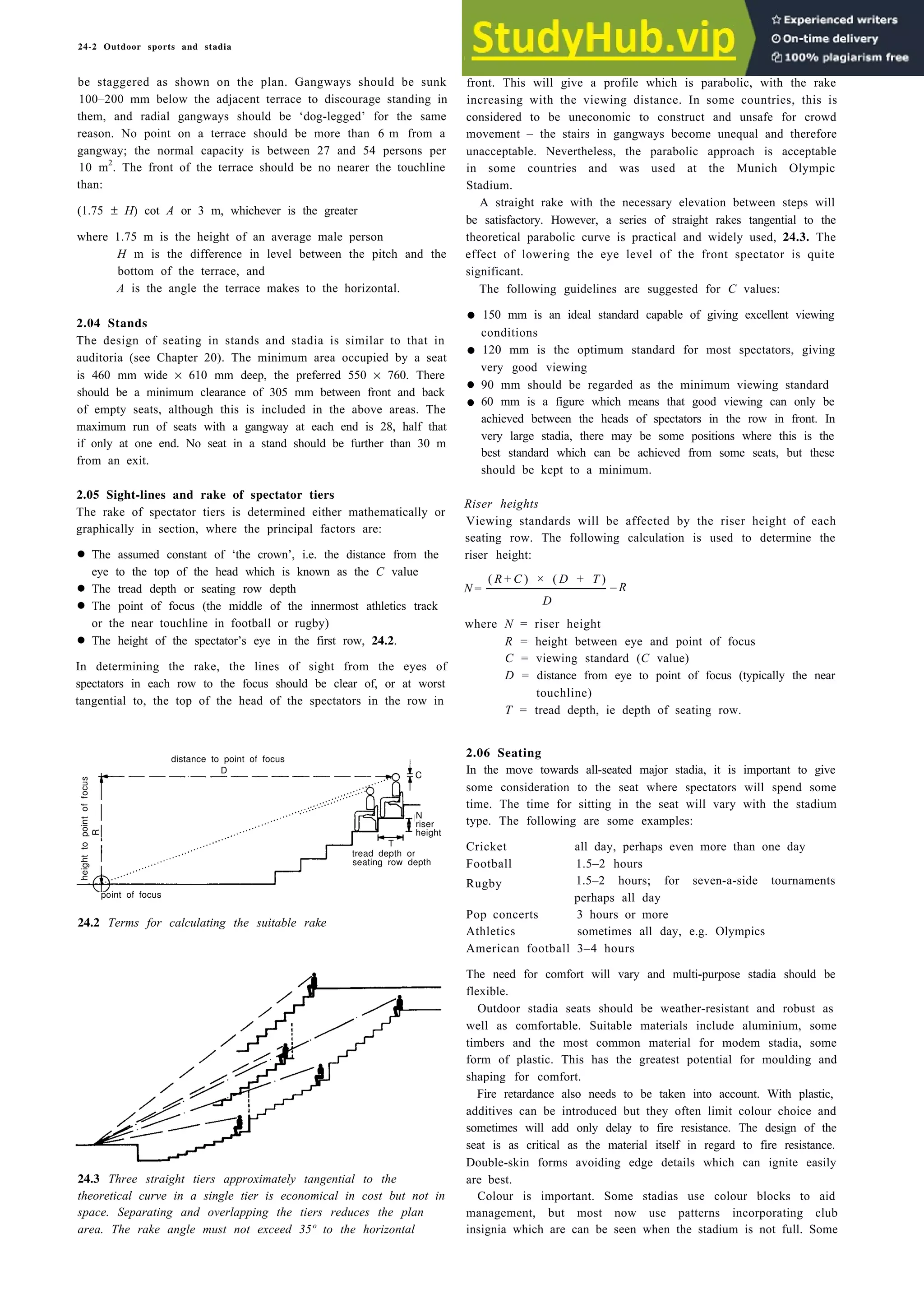
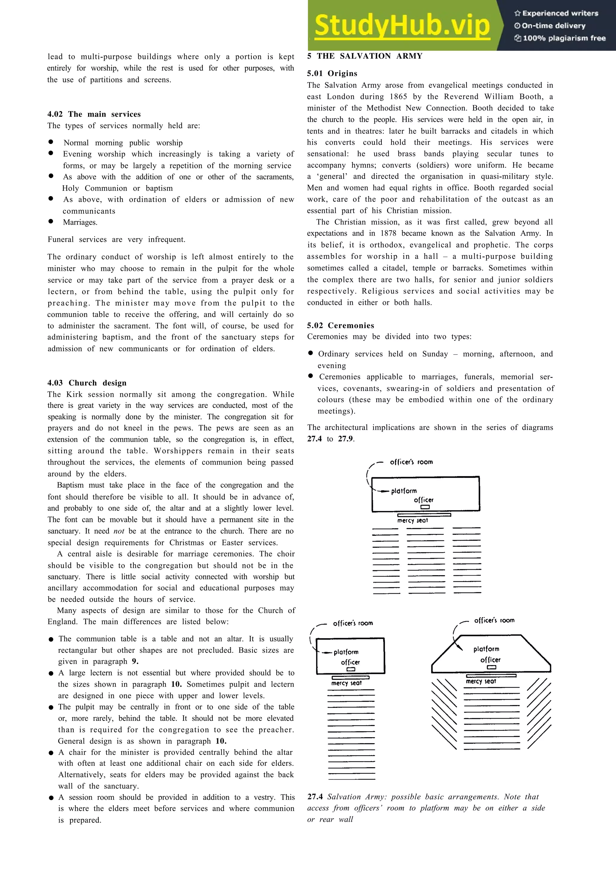
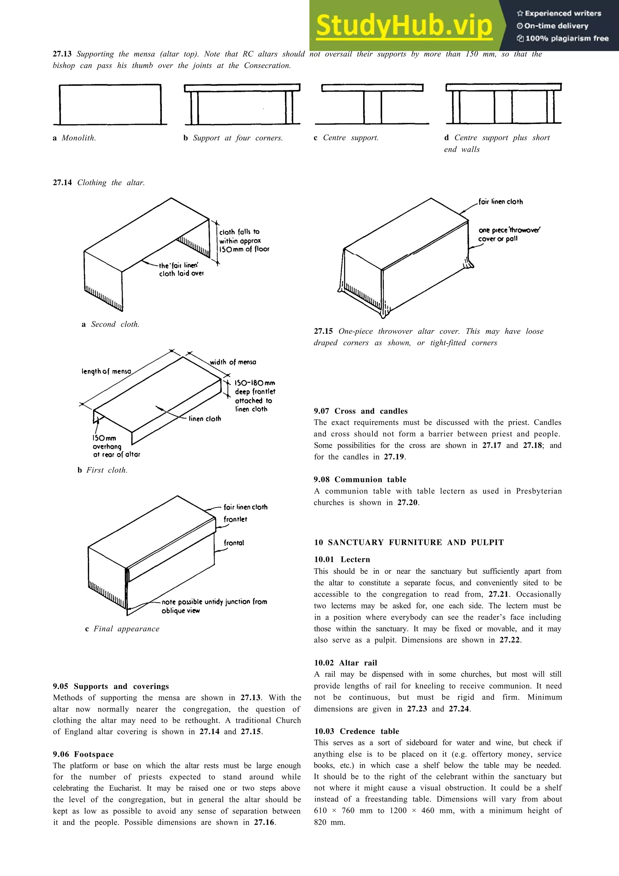
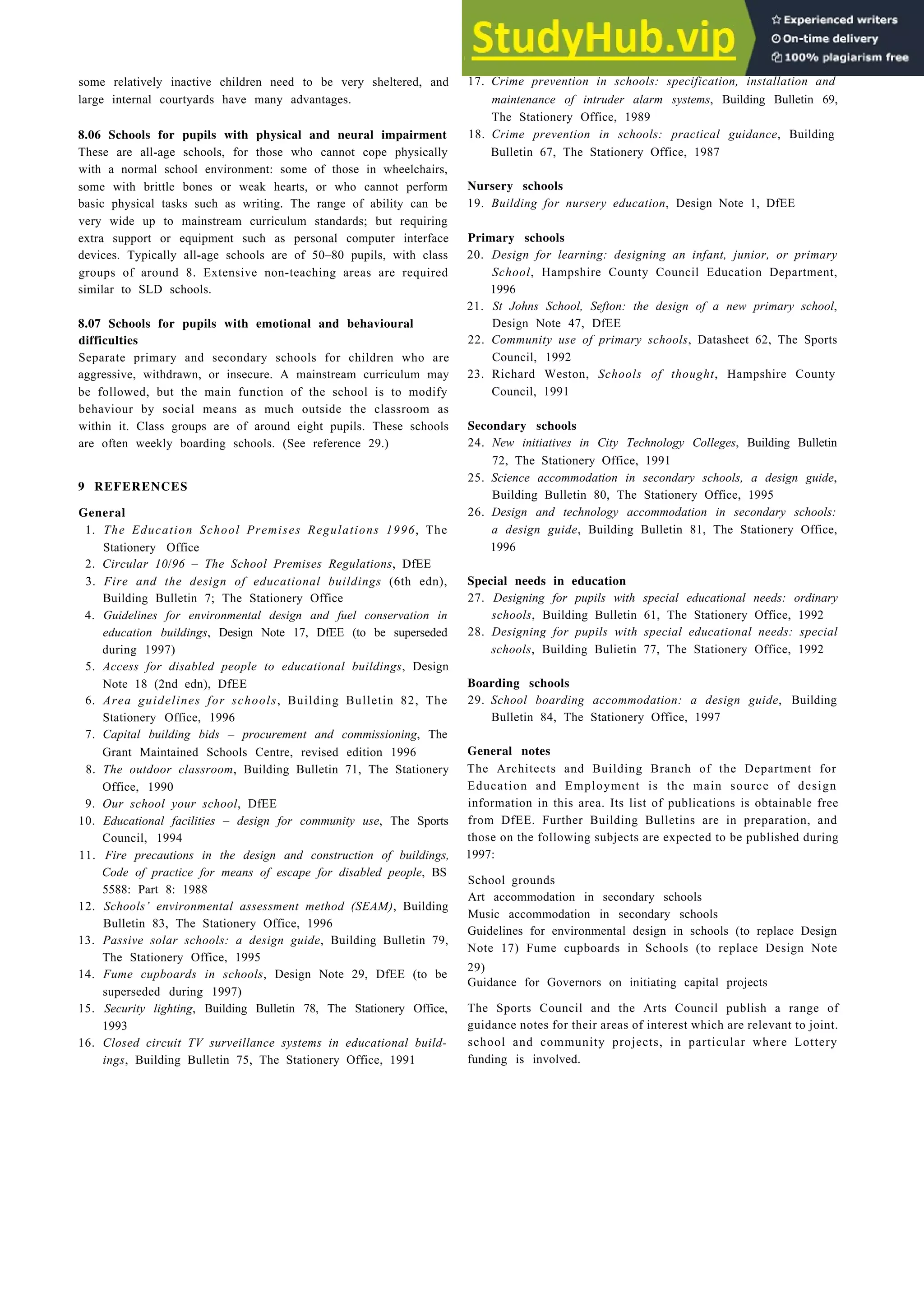
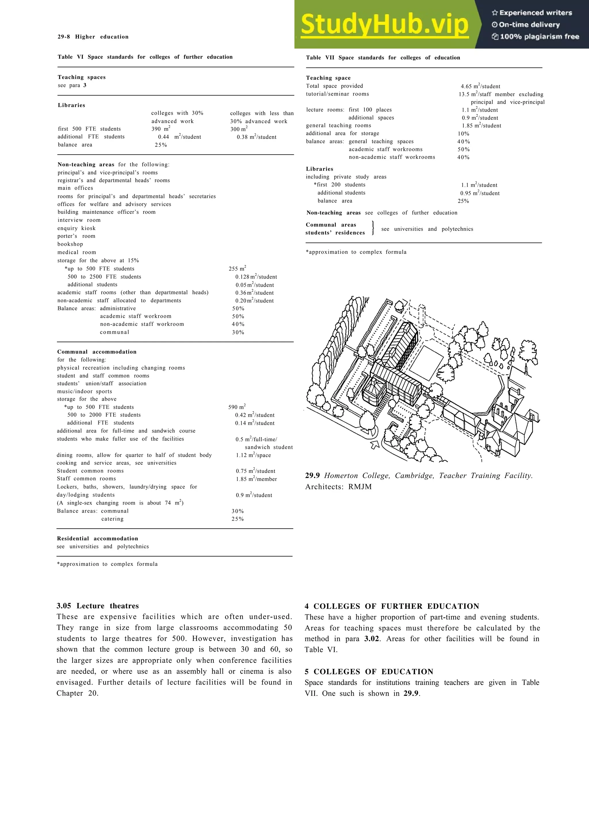
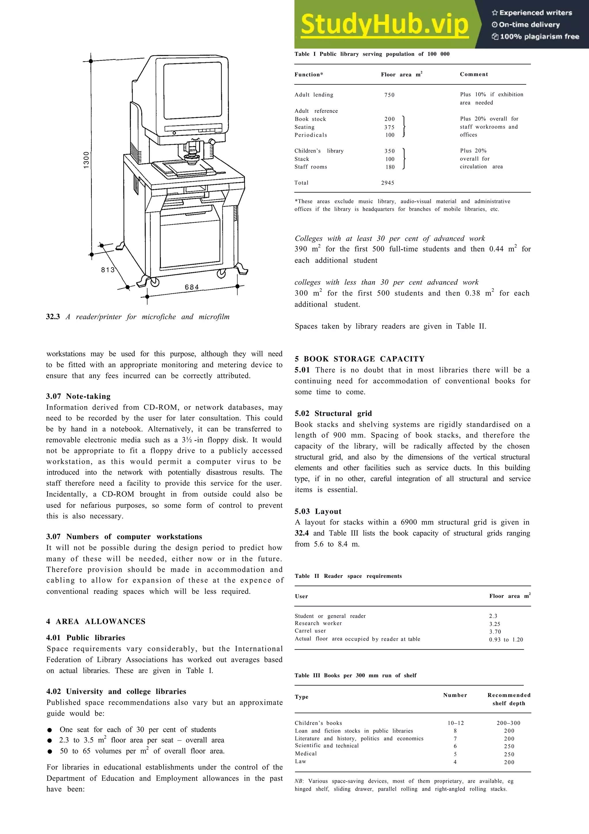
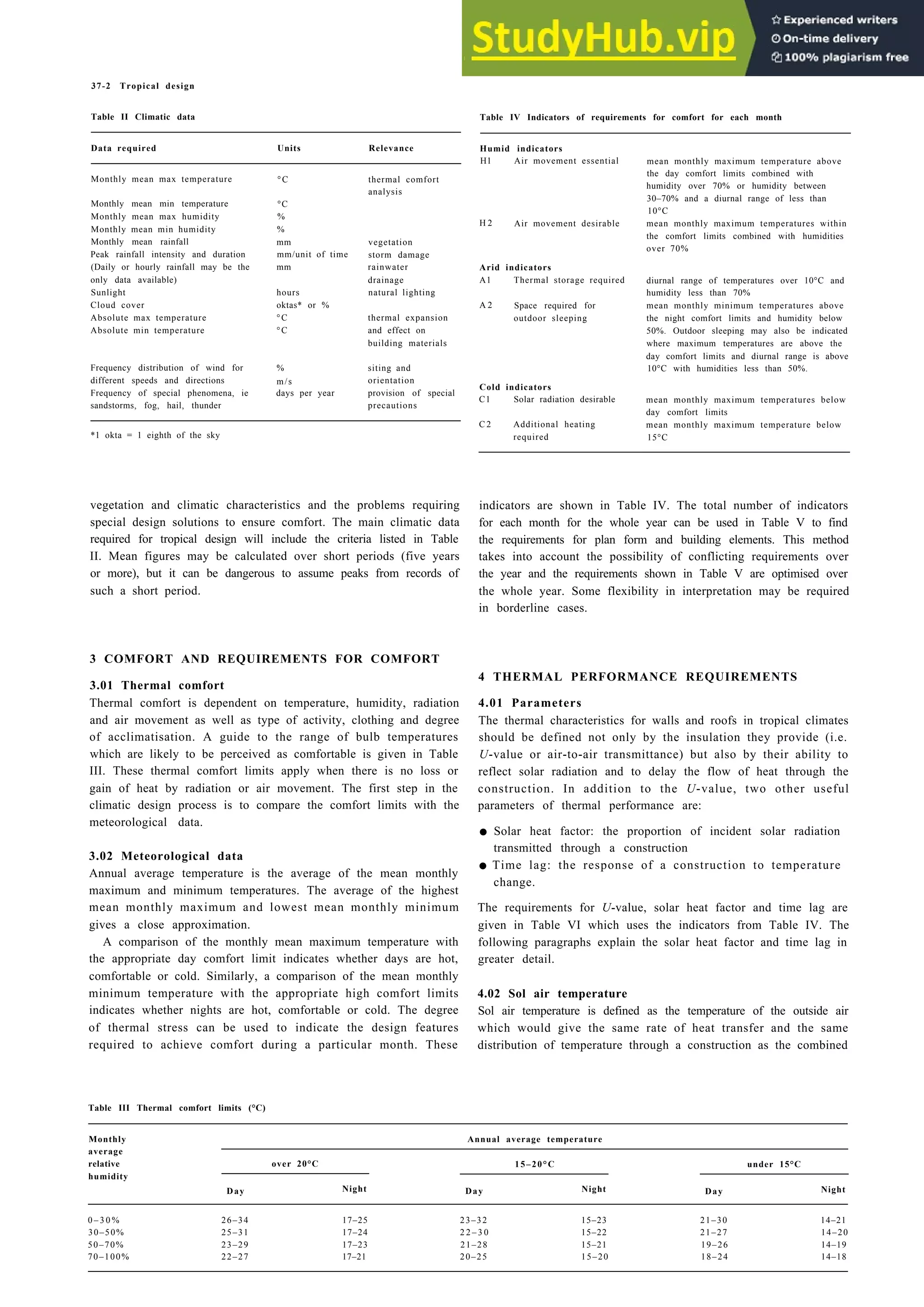
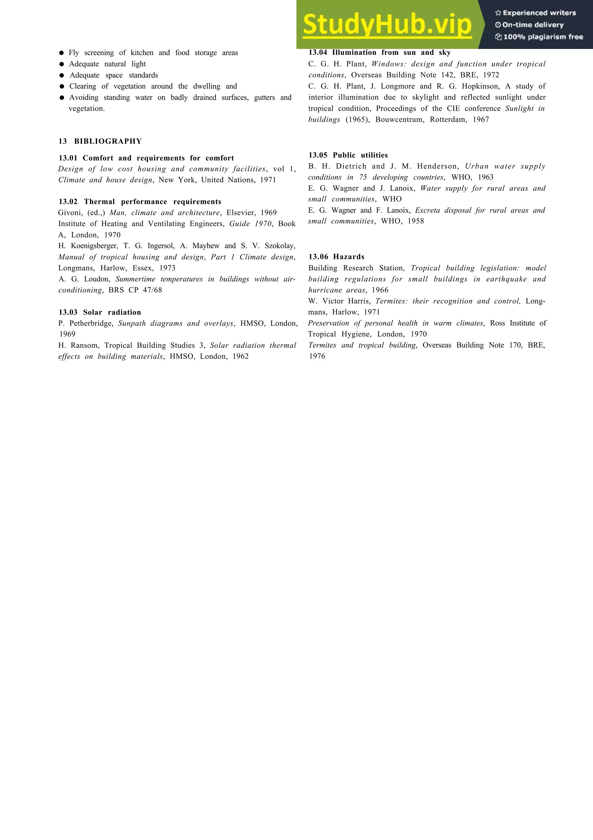
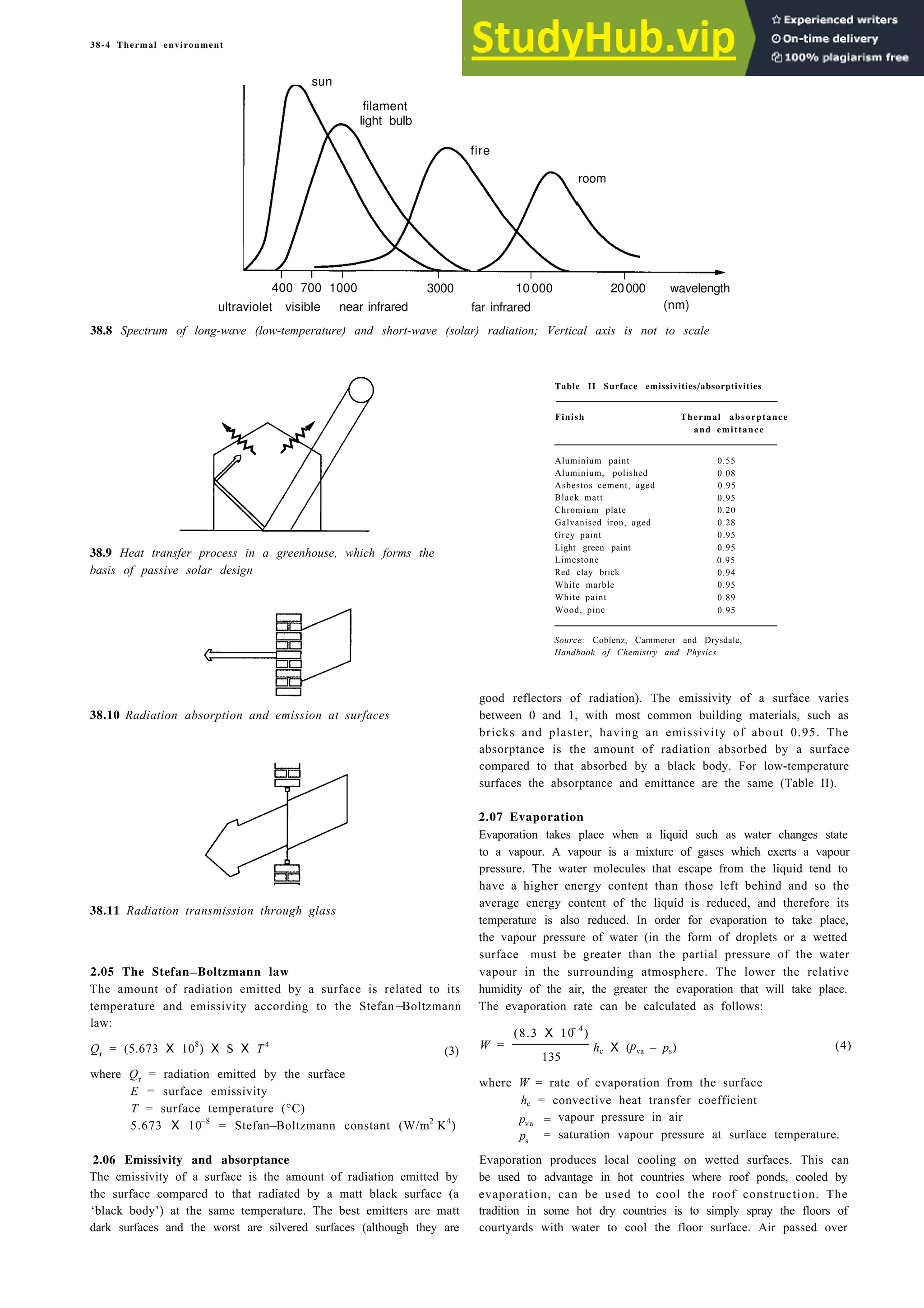
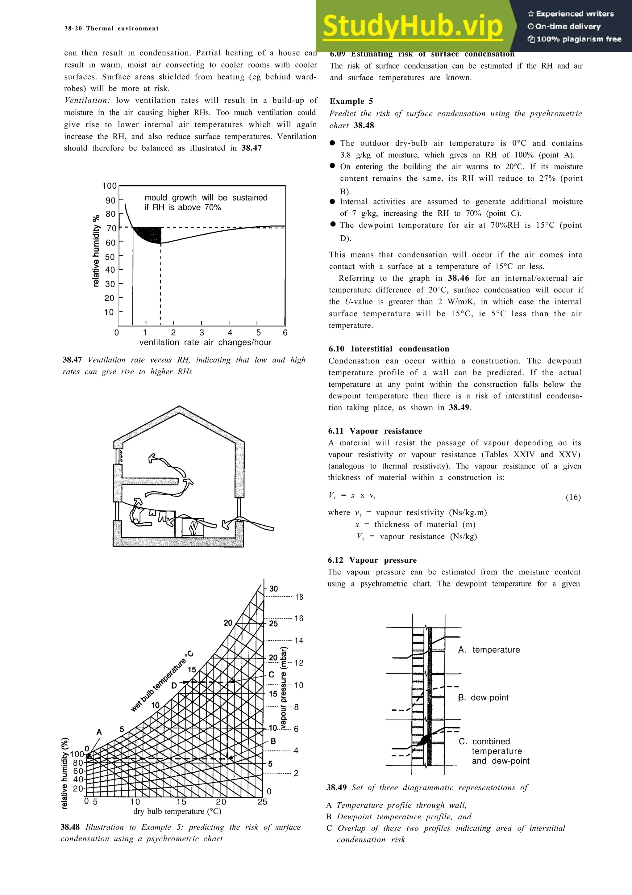
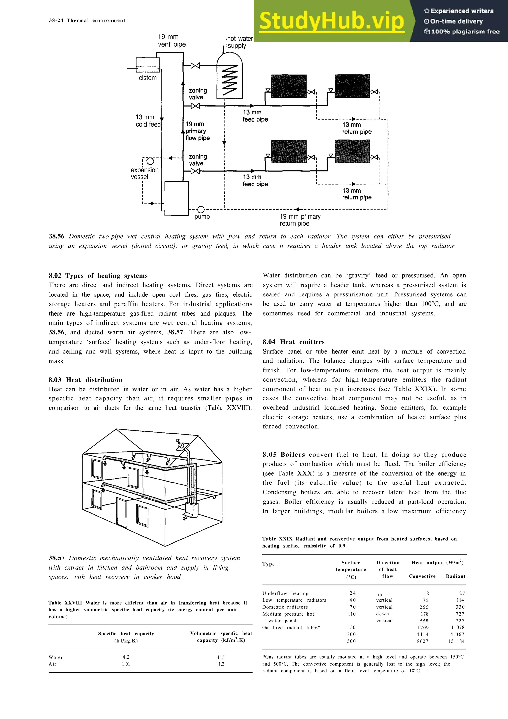
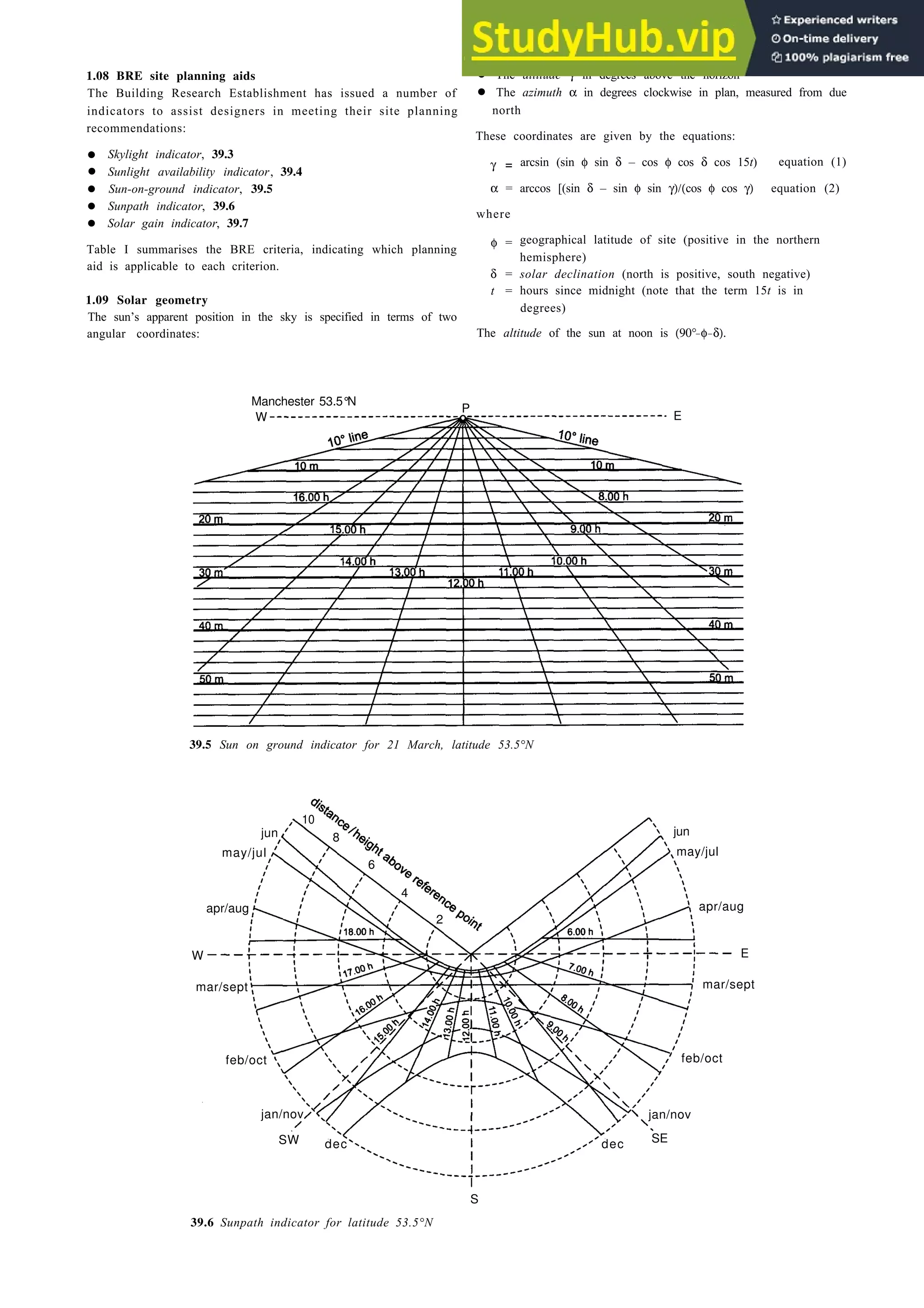
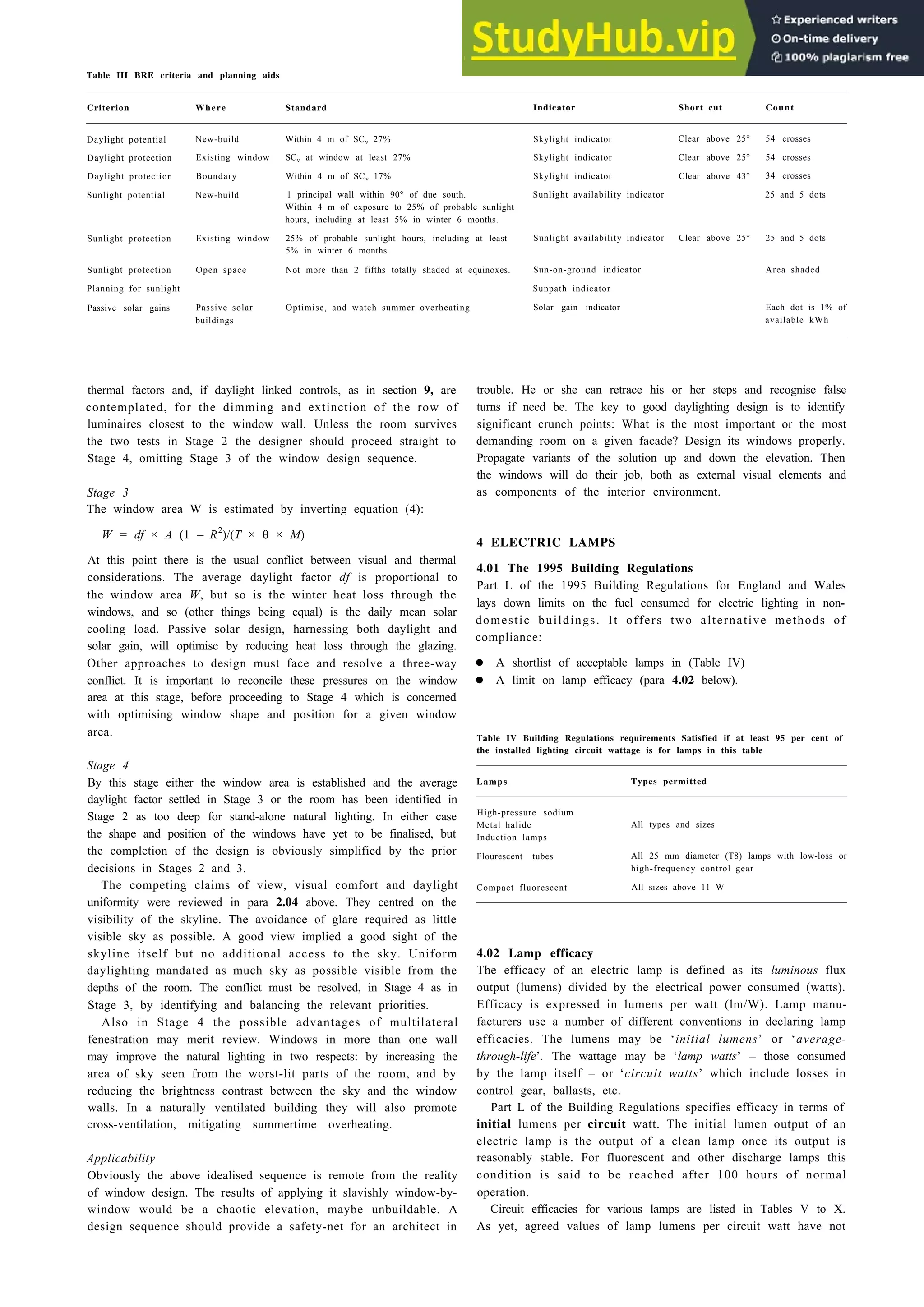
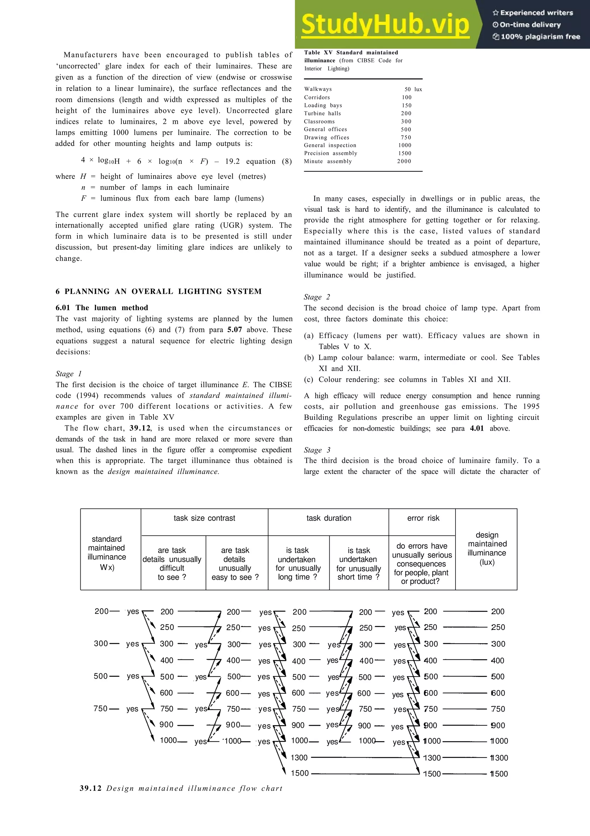
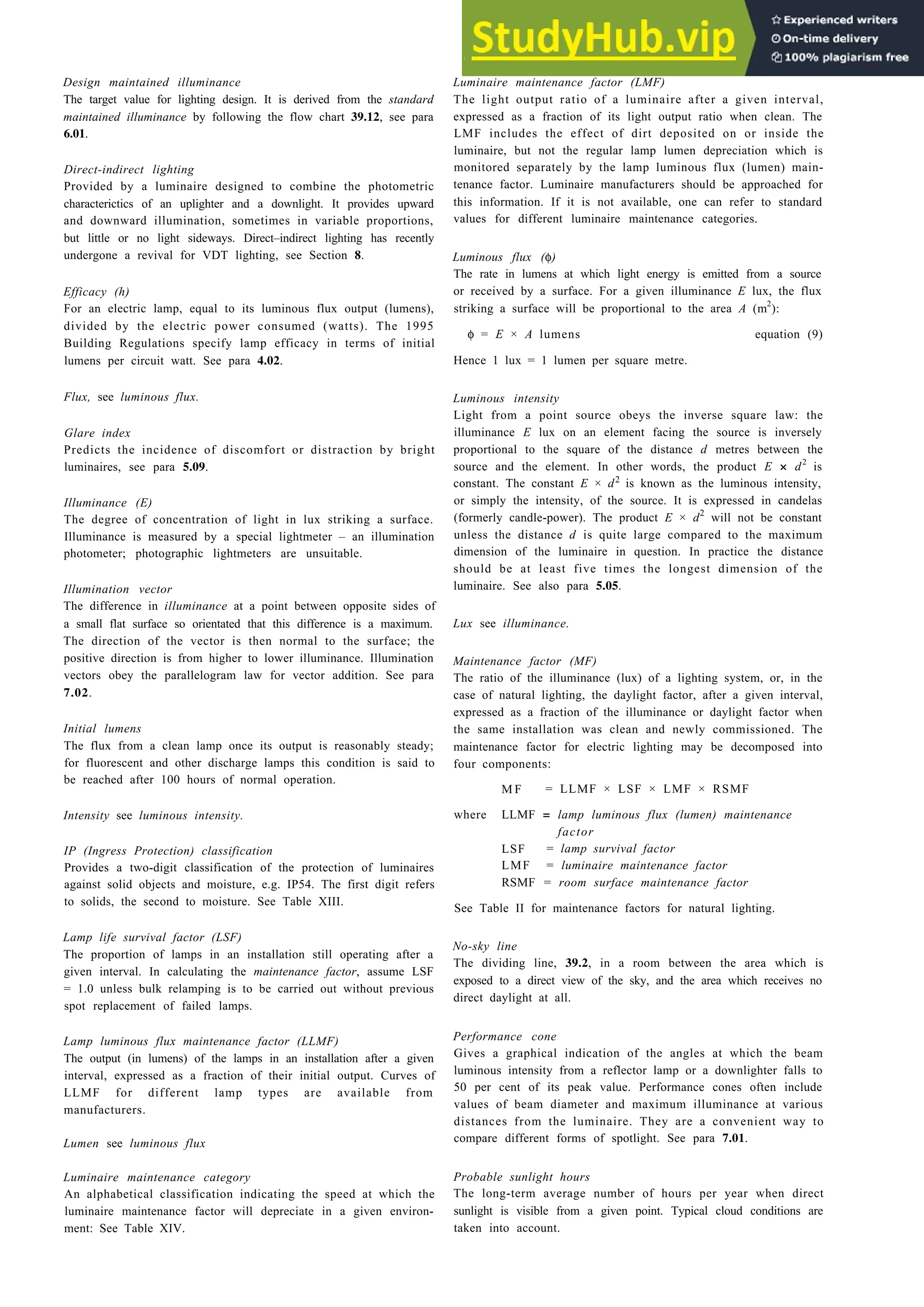
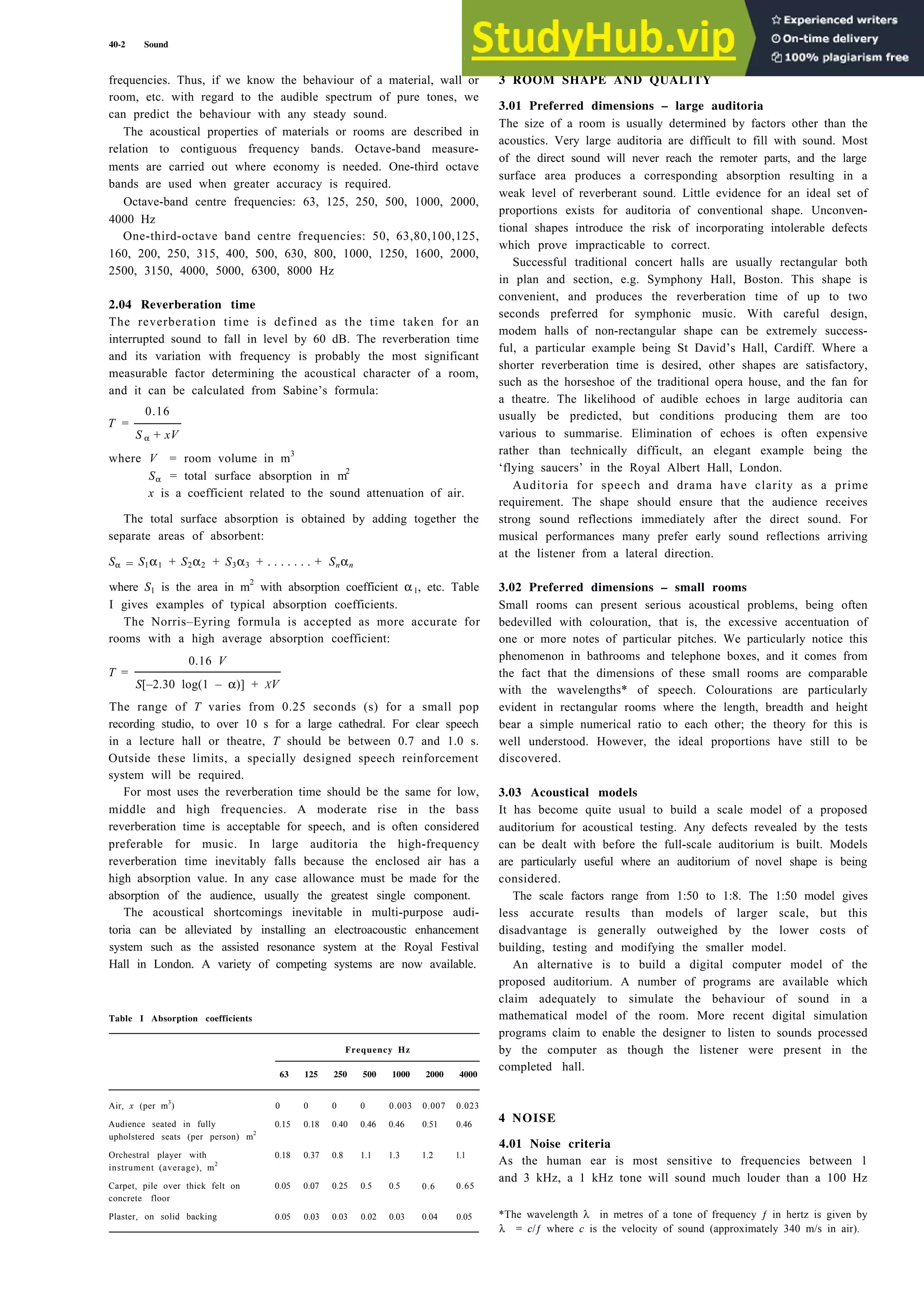
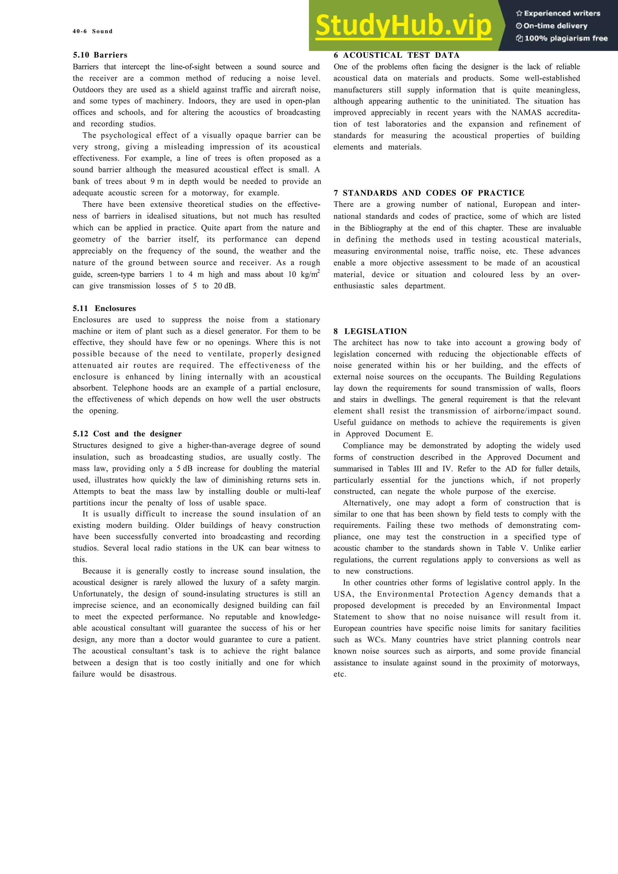
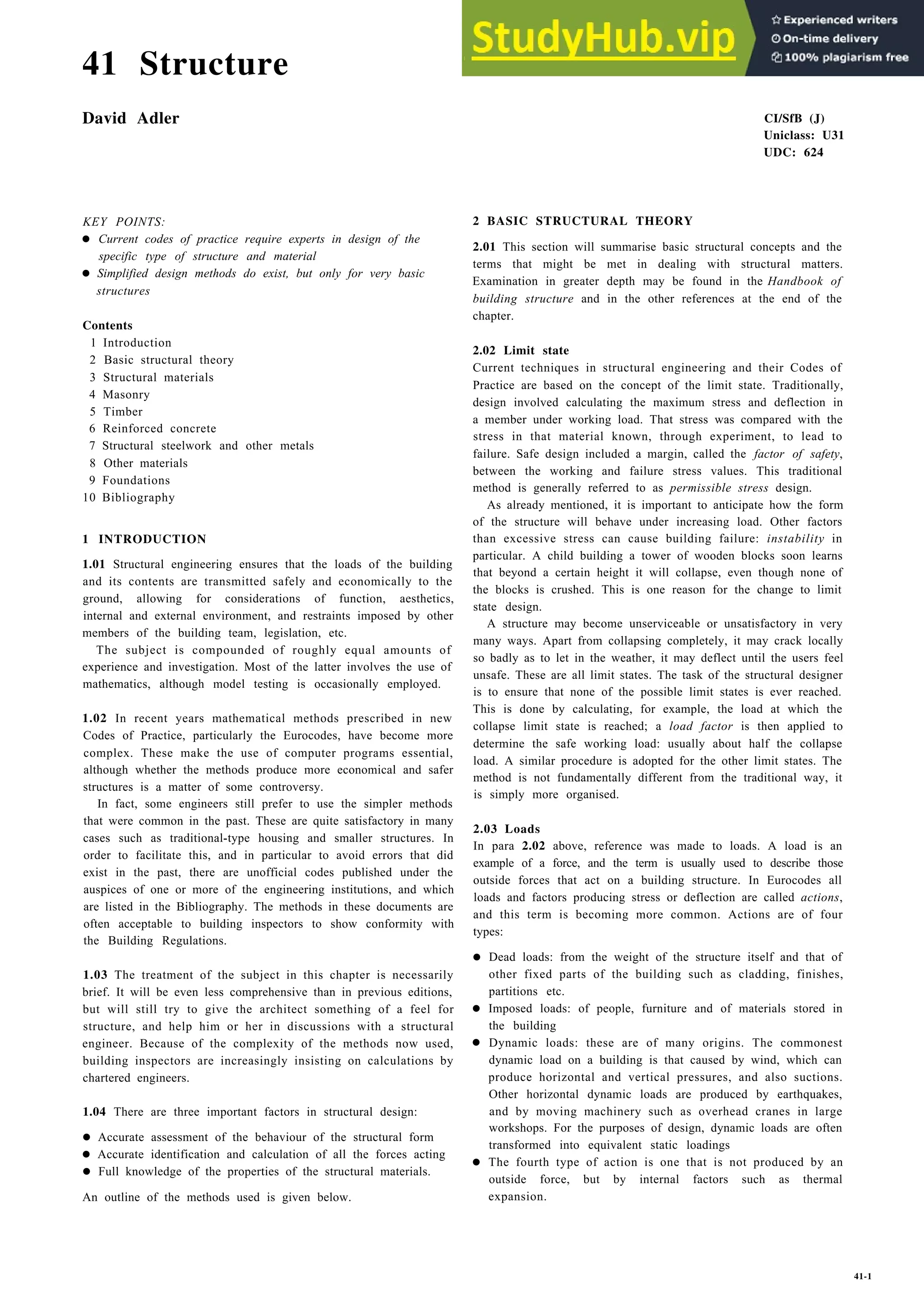
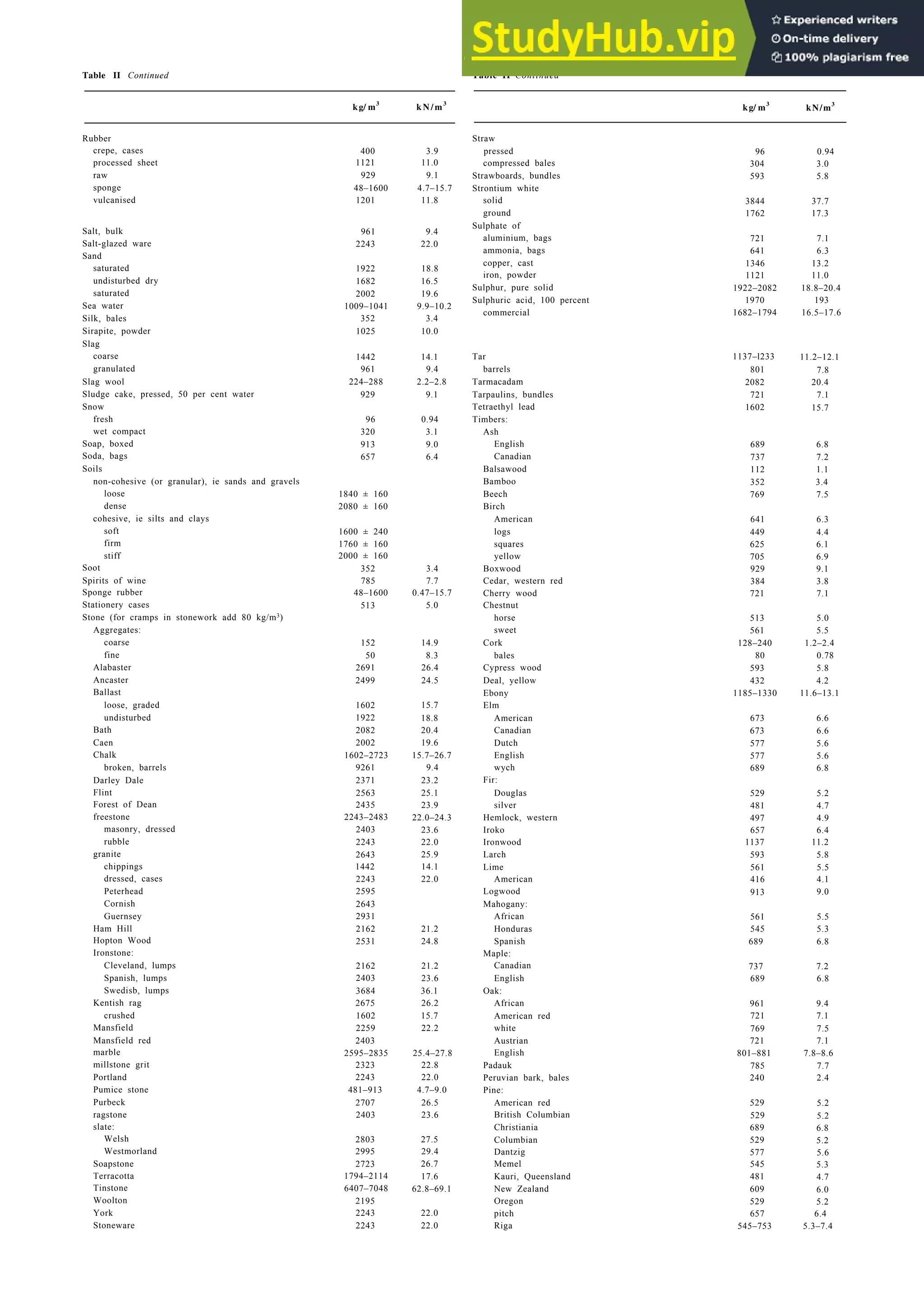
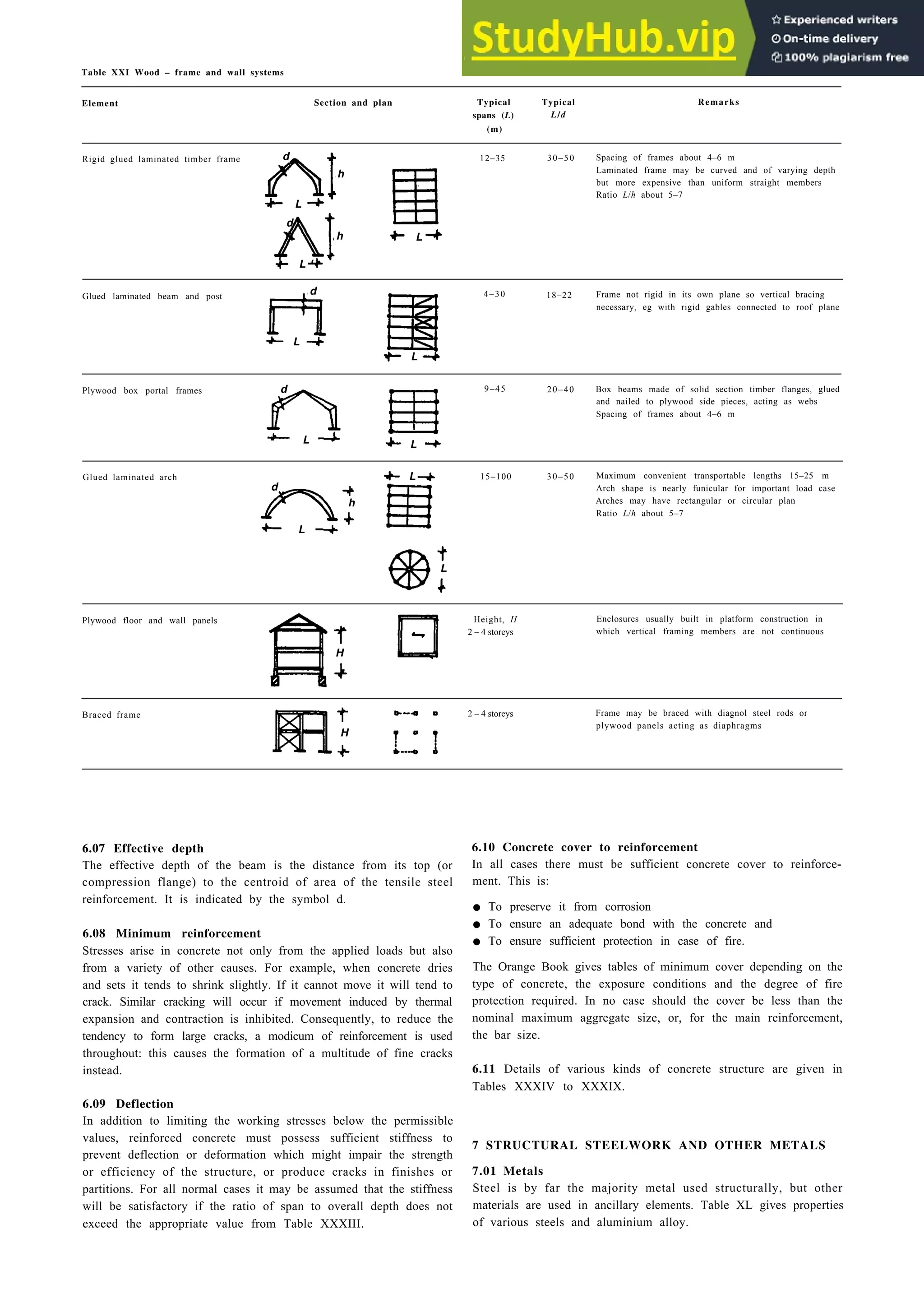
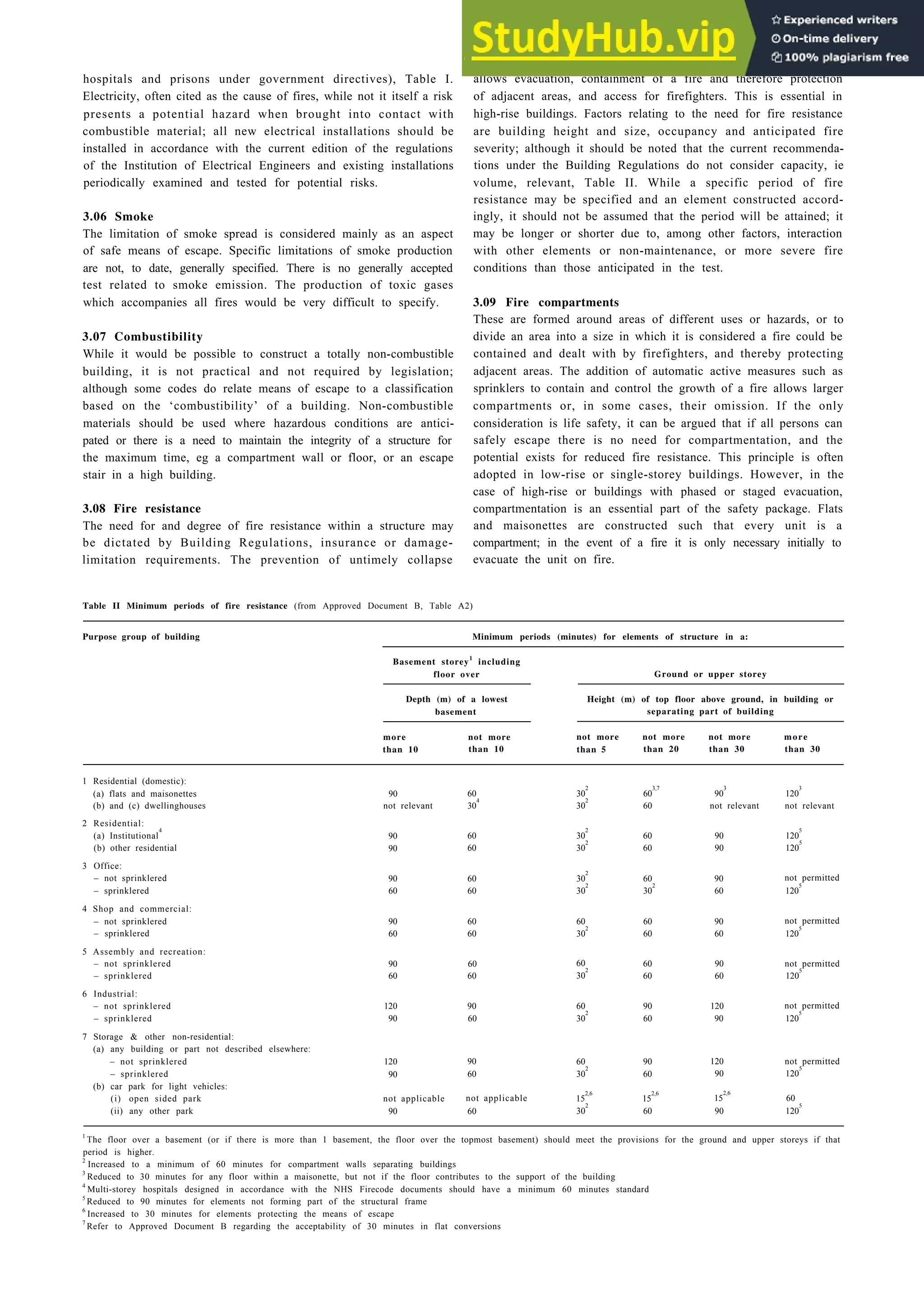
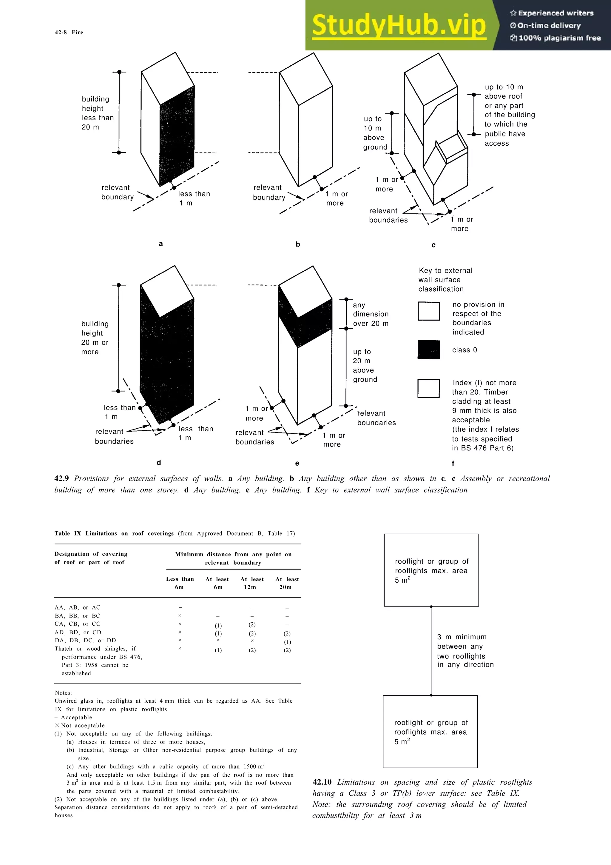
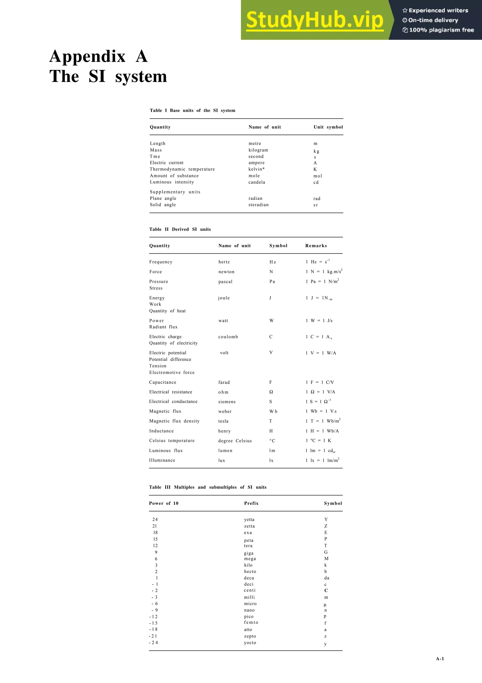
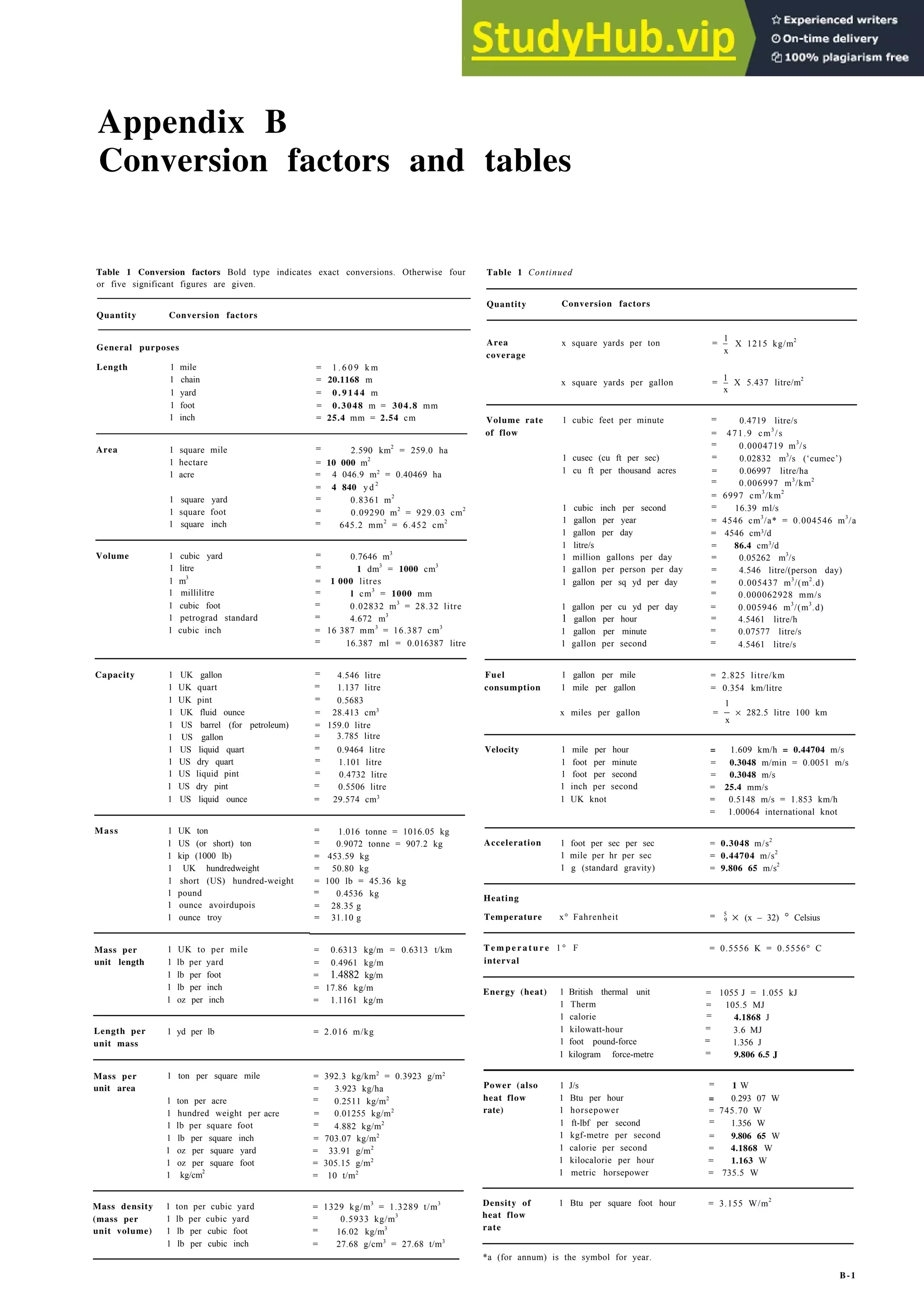
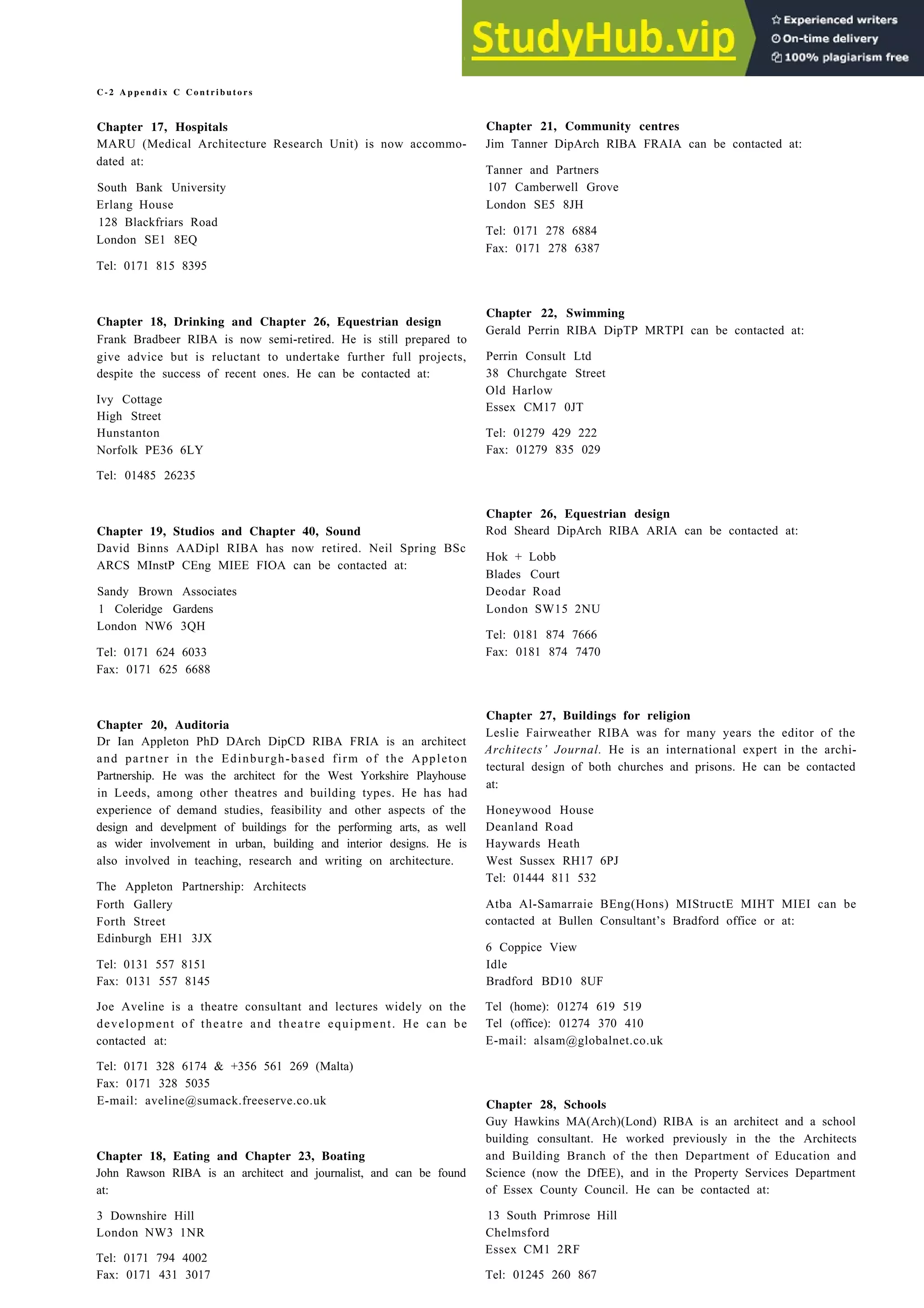
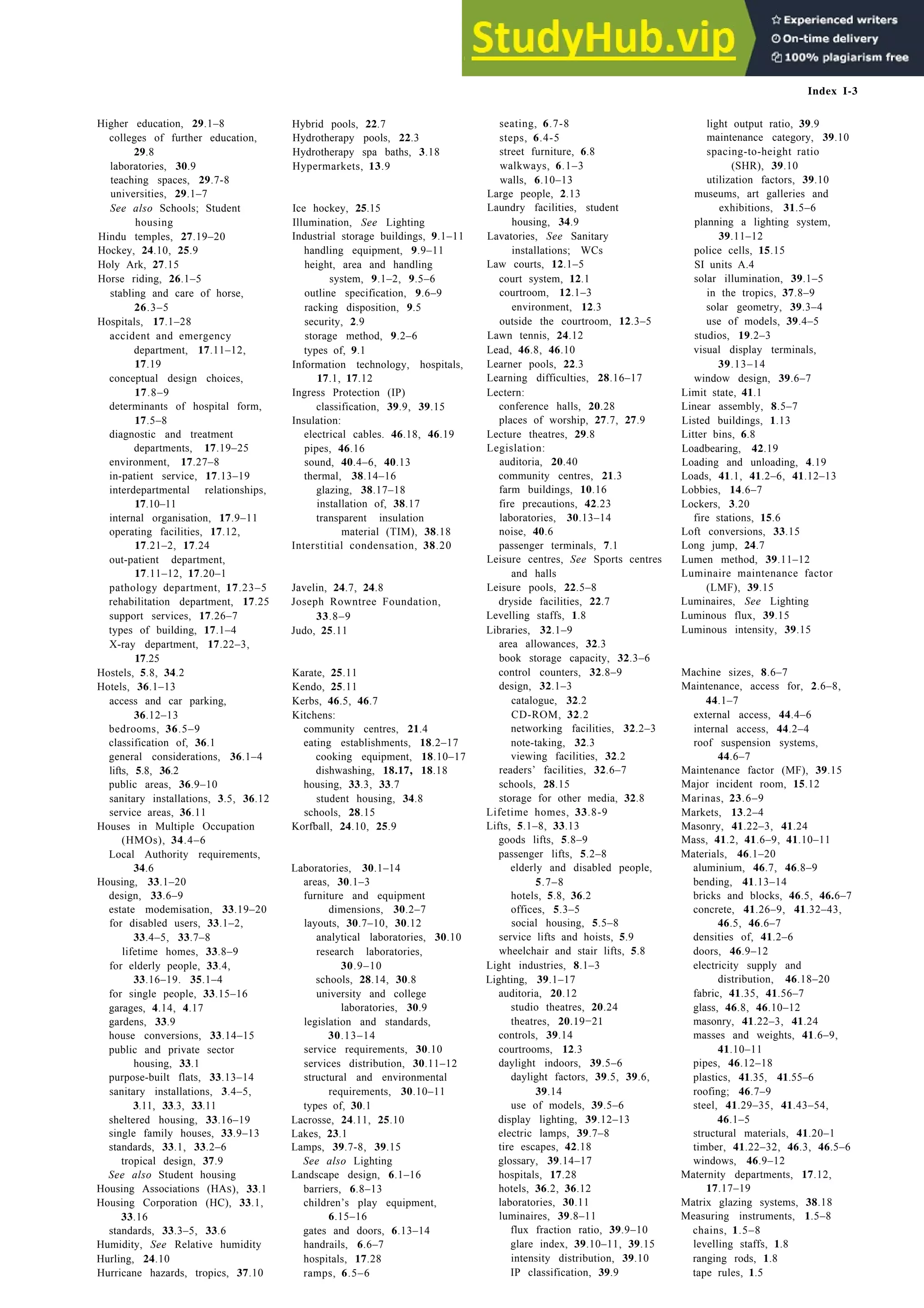
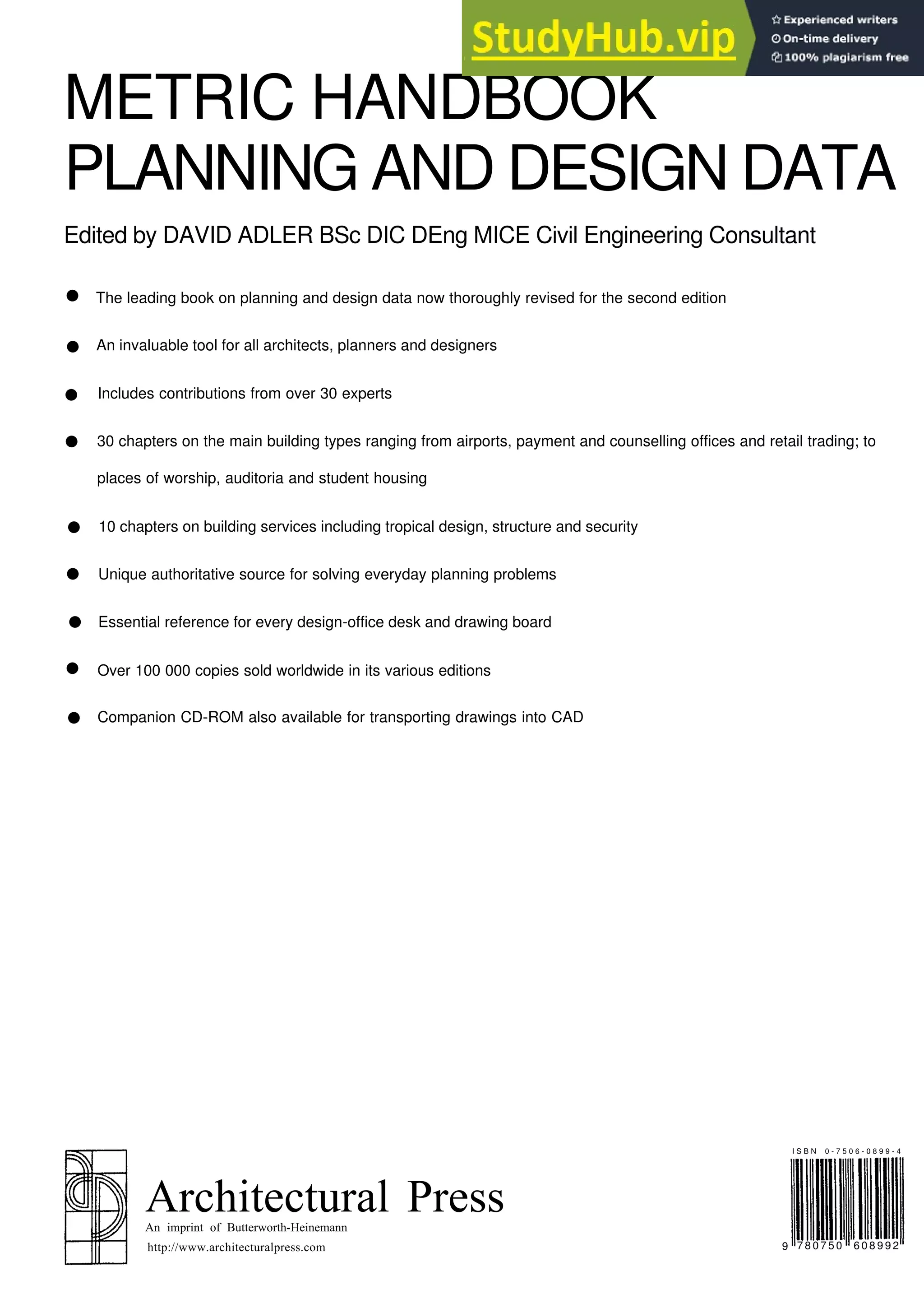
25.50 Athletics: indoor tracks 200 and 160 metre laps, with straight sprint in centre. See Table IV for dimensions. It is no longer
considered satisfactory to fit a running track inside the cycle track in 25.53. If spectator accommodation is needed around the track,
a building of considerable clear span is necessary as supports in the central area are not acceptable
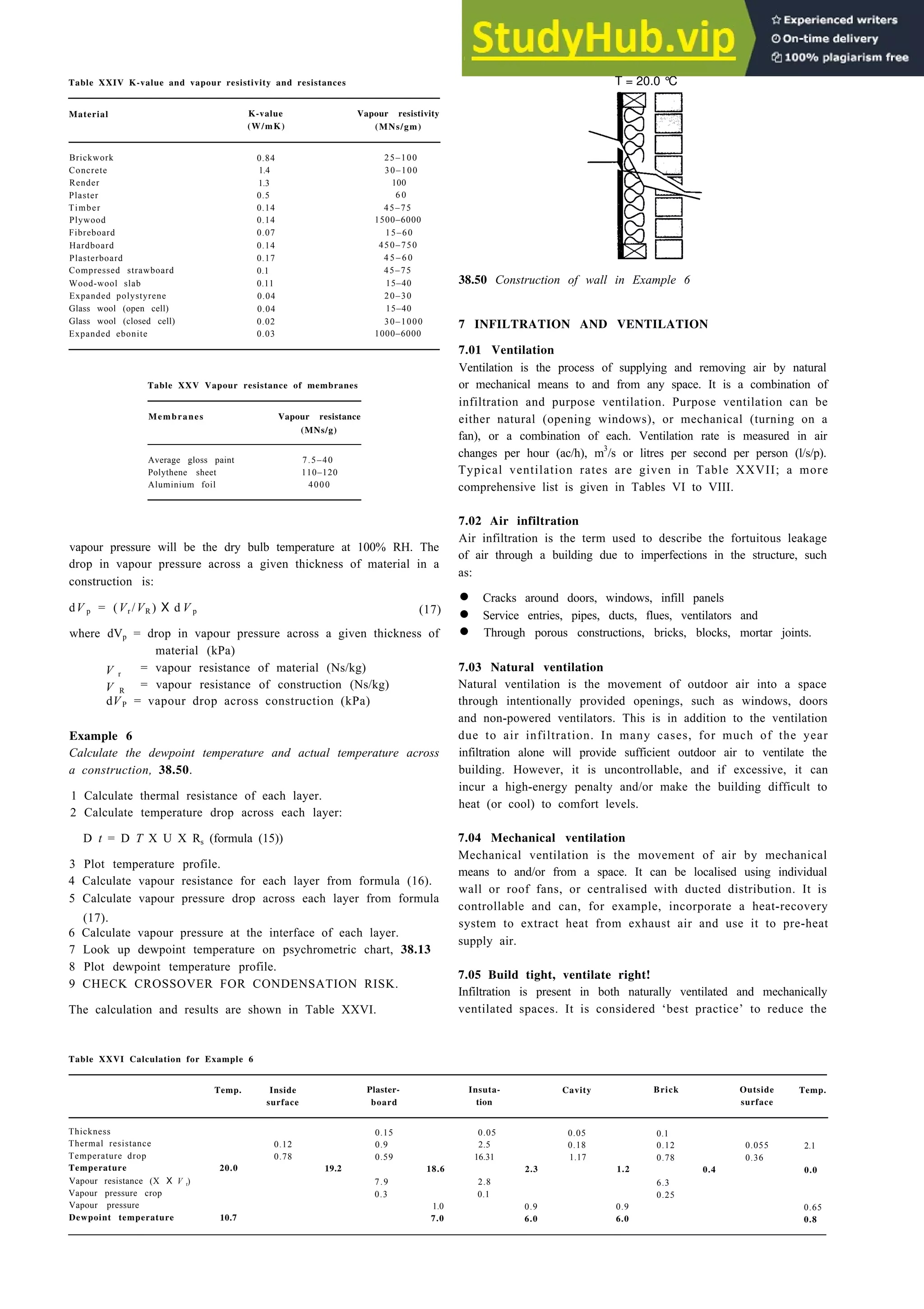
25.51 Billiards and snooker. The
agreed international size, due to
become mandatory in 2025, of 3.5 ×
1.75 m measured inside the cushions,
has had little acceptance, even in
major competitions
25.52 Bowling. Four rinks are the minimum for recreation,
six are required for tournaments
41
.
34
54
.
34
6
.
5
5.0 100.23 5.0
[24.48] can be used internally
sprint straight L2
overall length L1
6
.
5
110.23
straight S](https://image.slidesharecdn.com/architectureebookmetrichandbookplanninganddesigndata-230807180049-33007df6/75/Architecture-Ebook-Metric-Handbook-Planning-and-Design-Data-pdf-418-2048.jpg)


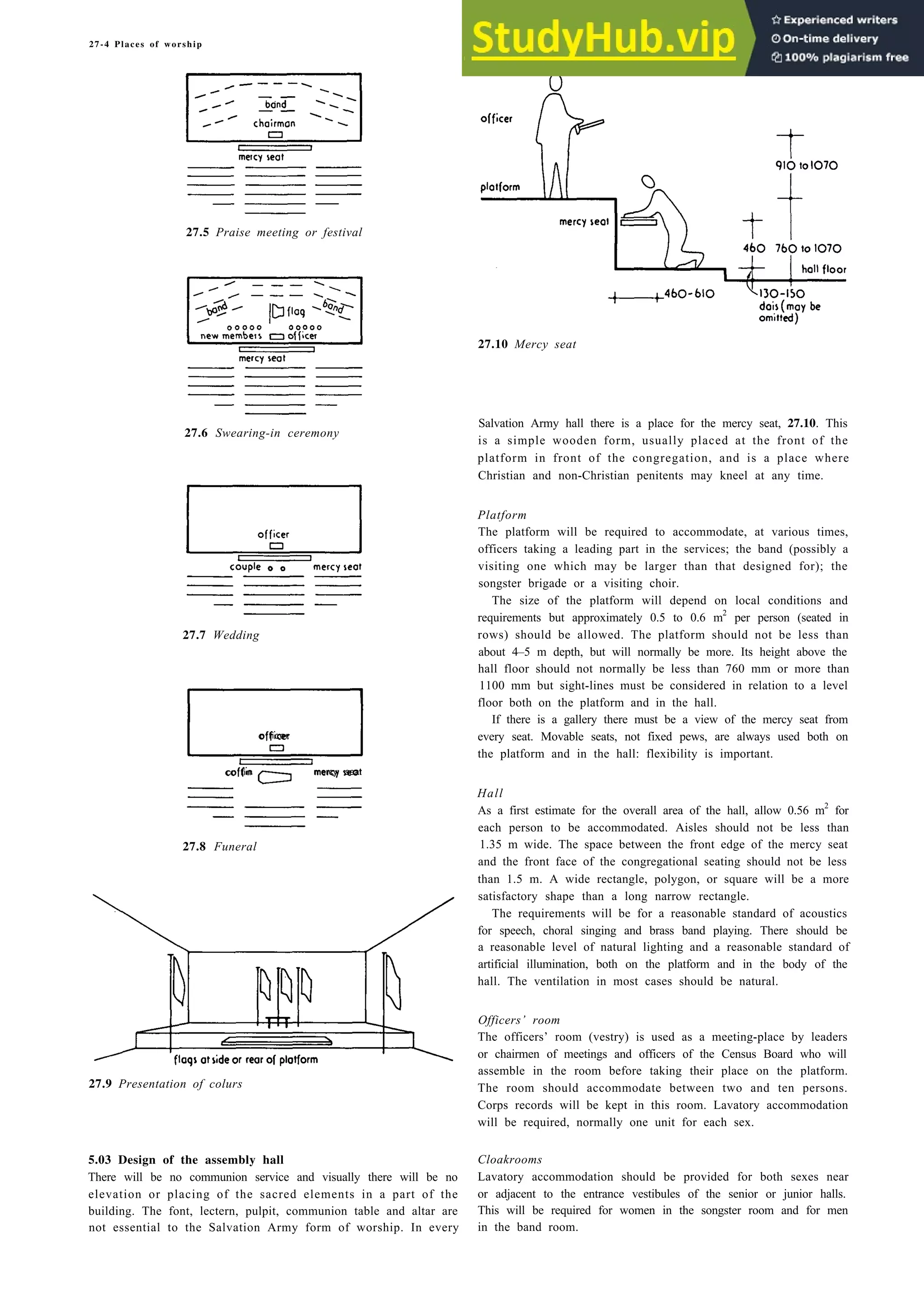


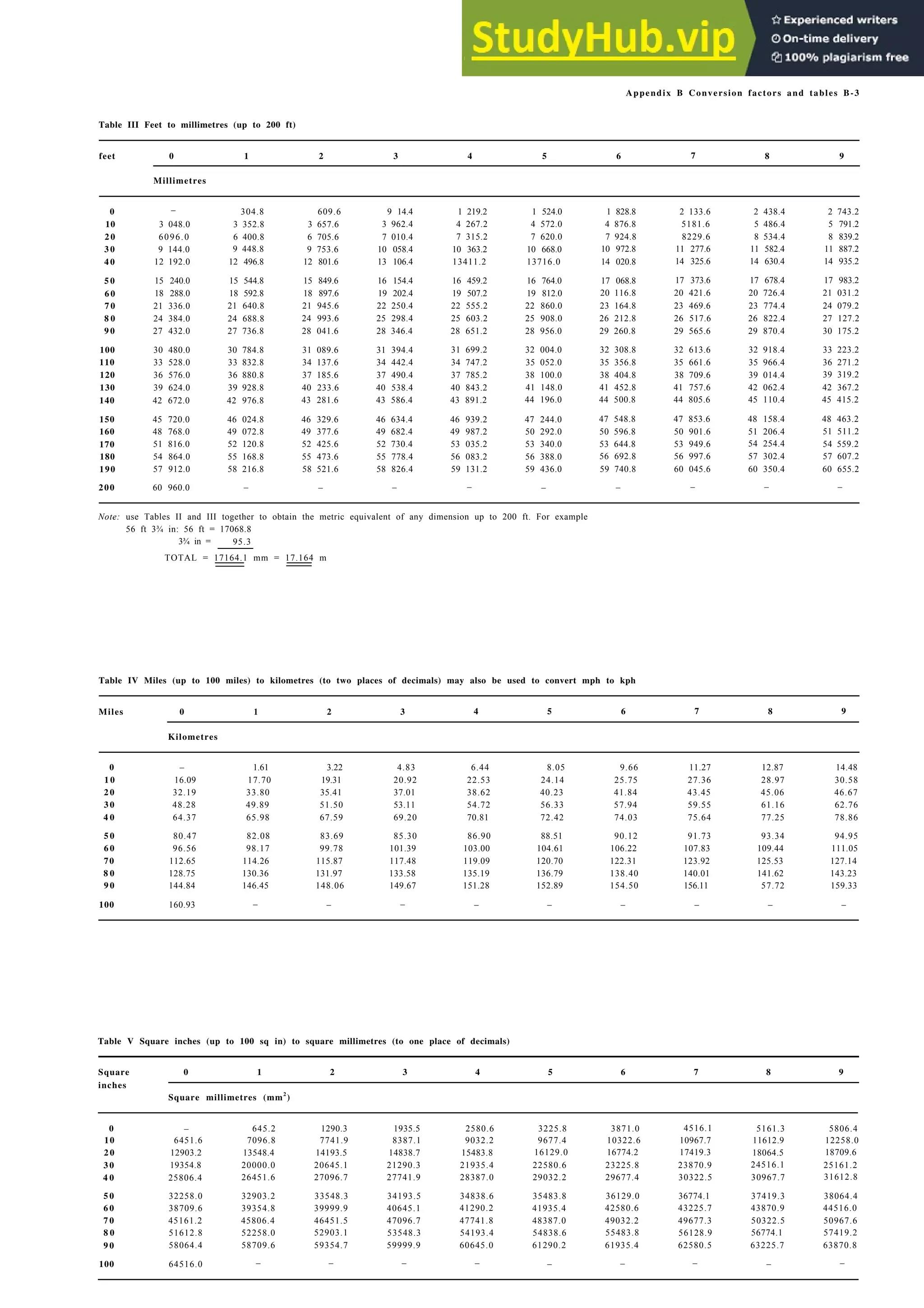


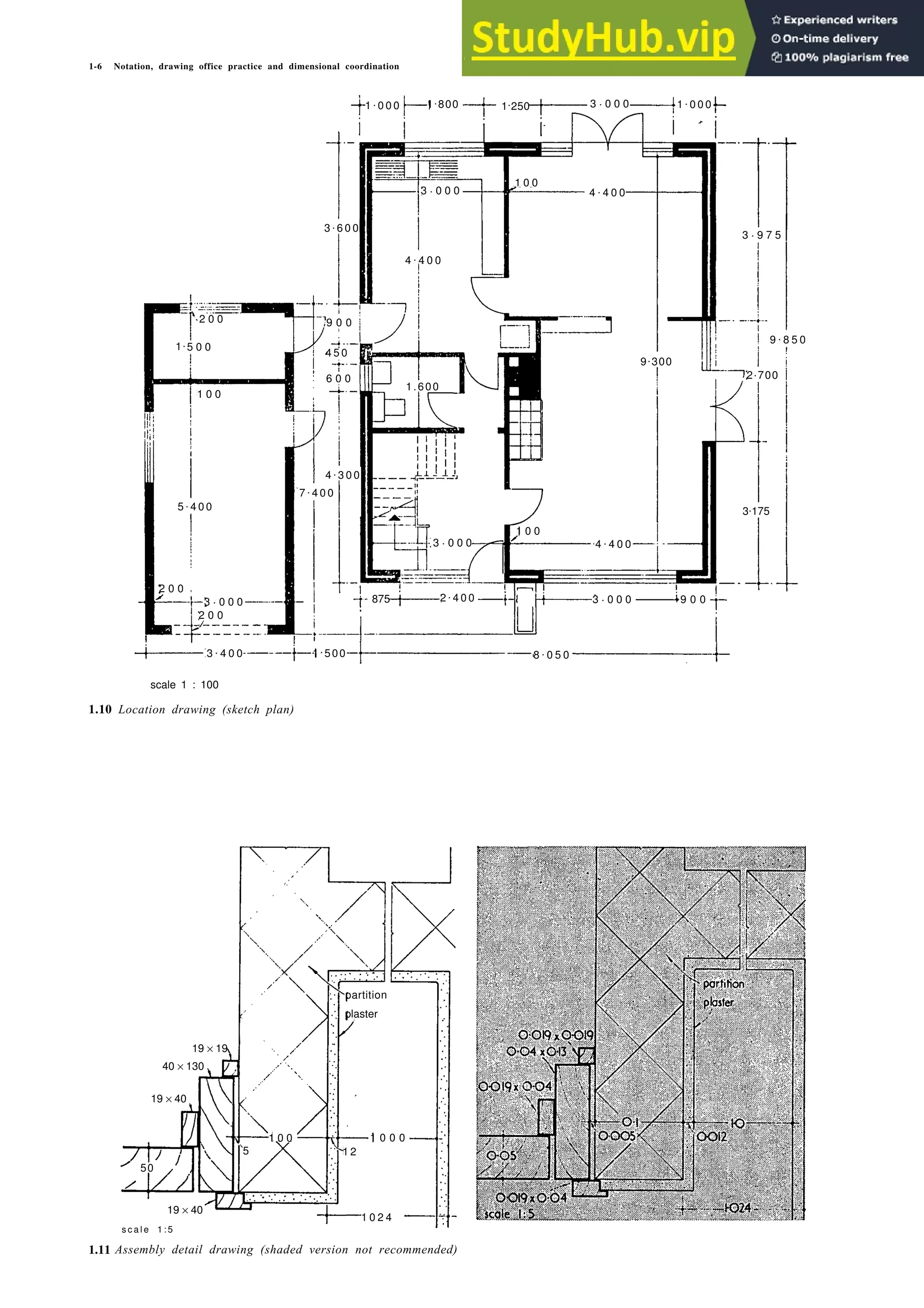
- The Metric Handbook provides guidance on notation, drawing office practice, and dimensional coordination when using metric units. - It outlines conventions for decimal markers, symbols, notation, and other drafting standards to ensure clear understanding. - Dimensional coordination is important, with components generally expressed in consistent units, and distinctions made between metric and imperial units of measurement.


