SlideShare a Scribd company logo
1 of 20
Download to read offline
Figure 8.1  The La Chapelle floor plan represents real framing to carpenters who read, visualize, and build from a set of plans.
Architectural Working
Drawings
8
Chapter
M08_POWE4171_01_SE_C08_074-093.indd 74 12/4/14 4:03 PM
Chapter 8 Architectural Working Drawings     75
Variation on framing for La Chapelle Plan Set Plan
M08_POWE4171_01_SE_C08_074-093.indd 75 12/4/14 4:03 PM
76    section Three  Project Planning and Architectural Plans
O b j e c t i v e s
Architectural Plans and Plan
Sheets
Contract-related documents include the final building contract,
detailed specification sheet(s), and working drawings for con-
struction. This set of paperwork becomes part of the legal founda-
tion for the project. Each document is vital to the building process.
The various plan sheets listed below make up the working draw-
ings that builders and subcontractors typically use to develop their
estimates. Carpenters will use the same drawings to interpret the
design and build the structure.
Many people refer to a set of working drawings as plans or
blueprints. In fact, working drawings are part of the complete
set of architectural plans. Architectural plans include working
drawings, schedules, and other sheets shown in the list below.
Many architectural plan sheets are horizontal (section) views of
the building. The most common plan sheets include floor plans,
foundation plans, and roof plans. The order of plan sheets gen-
erally follows the order of the building process. Elevation views
are usually before building plans to give builders, homeowners,
and trade workers a sense of how the entire project will look on
completion. Not all architectural plan sets will include each sheet
listed below.
	1.	Title and Legend Sheet(s)
	2.	Plot Plan (site plan)
	3.	Elevations
	4.	Foundation Plan
	5.	Floor Framing Plans
	6.	Floor Plans
	7.	Ceiling Framing Plans
	8.	Roof Framing Plans
	9.	Window and Door Schedules
	10.	 Details and Section Views
	11.	 Interior Elevations
	12.	 Trade Plans (Mechanical, Electrical, Plumbing)
	13.	 Specifications
The sophistication and detail in a set of construction plans
may vary based on building design, owner’s need, and the ar-
chitect. In any case, enough detail is required to help minimize
mistakes and facilitate coordination within the various trades,
subcontractors, and materials suppliers. In drawing construction
plans, architects, drafters, or builders will illustrate many details
in only one place to eliminate confusion and redundant informa-
tion. For instance, specifying the same stud spacing on every wall
section is not required for most plans.
Title Sheets
The title sheet (Figure 8.2) is the cover for a set of architec-
tural plans. On new construction, the title sheet typically has
a front elevation view of the home. The title sheet normally
includes all pertinent information about the primary parties
involved with the project. The title sheet will list the architect
(designer), owner, builder, and major subcontractors, and it
may include a green home certification program’s seal and the
green verifier’s information. Other sheets in the plan set will
use a title block. The title block organizes some of the same
information from the title page for quick reference on each
page. Page numbers will be part of a title block to help keep
drawings organized.
Plan Visualization
Visualizing the finished home or addition by reviewing a set of
working drawings is a learned skill developed by builders, car-
penters, and other craftspeople. It takes practice to develop the
spatial skills necessary to visualize a three-dimensional building
represented on a two-dimensional sheet of paper. Experienced
carpenters can take a virtual tour in their minds of the finished
building as they read and interpret information in a set of ar-
chitectural plans. As this chapter covers each plan sheet, draw a
mental picture to visualize the information and begin developing
spatial skills. Figure 8.1 illustrates how the 2-D drawing becomes
a real 3-D structure.
Orthographic Projection
Drafters, engineers, architects, and builders use a system known as
orthographic projection to create drawings of three-dimensional
buildings on two-dimensional paper. Ortho means “straight
line” and this projection provides a graphical representation on a
two-dimensional plane. The projection represents objects drawn
with a common relationship; that is, they are in scale with each
other. Common perspectives and drawing techniques are shown
in Figure 8.3.
Acommondrawingperspectiveprovidingathree-dimensional
view (3D) is the isometric view. Isometric views place all horizontal
lines at 30° angles relative to the horizon with vertical lines perpen-
dicular to the horizon. With this method, all lines are to scale and
remain in proportion. An example is shown in Figure 8.3.
n	Define and explain the various sheets that make up a set
of architectural plans.
n	Identify the sheets in a set of working drawings and ex-
plain the information available from each working drawing.
n	Define the most common scales used on architectural
plans. Explain why scales are important and what informa-
tion they make possible on a single plan sheet.
n	Give examples of electronic plan scaling aids and software
available to estimators and builders. Explain how these
tools help estimators work faster and more accurately.
n	Explain why section views and details are important plan
sheets. How do carpenters and other trade workers use
these views?
n	Explain how Building Information Modeling software helps
build energy-efficient homes.
M08_POWE4171_01_SE_C08_074-093.indd 76 12/4/14 4:03 PM
Chapter 8 Architectural Working Drawings     77
LICENSED LAND SURVEYOR
CODE ENFORCEMENT PLAN REVIEW APPROVAL
ONE
STORY
RANCH
W/
DETACHED
GARAGE
COVER
SHEET
&
SITE
PLAN
W.
KEITH
POWELL
N
02°00'00"
E
105.97'
S
05°0
0'00
"
W
158
.12'
N
7
0
°0
0
'0
0
"
W
1
1
1
.0
9
'
S 20°00'00" W
114.52'
12'-0" WIDE ASPHALT TRAVEL LANE
(60' PUBLIC RIGHT-OF-WAY)
4'-0" WIDE BIKE LANE
2' WIDE GRAVEL SHOULDER
8' WIDE UTILITY
EASEMENT
33.14'
47
.2
8'
17.70'
25' FRONT BUILDING SETBACK LINE
15'
SIDE
BUIL
DING
SETB
ACK
LINE
15'
SIDE
BUILDING
SETBACK
LINE
25' REAR BUILDING SETBACK LINE
2' WIDE GRAVEL SHOLDER
SAN
SAN
SAN
G
W
S
SL
SL
G
S
G
S
SL
W
S
W
S
G
G
G
G
E
E
E
E
E
W
W
W
4'-0" PUBLIC SIDEWALK
S 05°00'00" W 156.29'
PROPERTY BOUNDARY LINE
10'
88
.5
'
10'
MIN.
BENCHMARK
“X” ON TOP OF CONCRETE
HIGHWAY MONUMENT
ELEV. = 100.00
0 20 40
SCALE IN FEET
1” = 120’
SITE PLAN
SITE LOCATION MAP
SHEET INDEX
SAWYER
LANE
SAWYER
LANE
M
c
M
U
R
R
Y
W
A
Y
1 STORY
WOOD FRAME HOUSE
1,987 S.F
.
SUB-FLOOR ELEV. = 106.32
10’ WIDE DRIVEWAY
W/ TURN-AROUND
SEE NOTE 3 FOR
OPTIONAL SURFACES
D
R
IV
E
W
A
Y
DRIVEWAY MAY ALSO BE USED
AS CONSTRUCTION STAGING
UNTIL CONCRETE IS PLACED
AND FINISHED
LOT AREA = 26,548 S.F
. / 0.61 ACRES
PROPERTY BOUNDARY
C1
A1
A2
A3
A4
A5
A6
A7
S-1
D-1
D-2
D-3
COVER SHEET, SITE PLAN
SOUTH & EAST ELEVATIONS
NORTH & WEST ELEVATIONS
FOUNDATION PLAN
FIRST FLOOR FRAMING PLAN
FIRST FLOOR PLAN
CEILING FRAMING PLAN
ROOF FRAMING PLAN
CROSS SECTIONS & INTERIOR ELEVATIONS
DETAILS
DETAILS
DETAILS
WINDOW SCHEDULE
A
B
C
D
E
F
G
H
I
J
K
L
M
N
O
P
Q
R
MODEL
MARK
(3) 3056DH/TR
3060DH/TR
2630DH
(2) 2030DH/TR
(3) 4050DH/TR
(2) 2056DH/TR
6010TR
(3) 3050DH/TR
2040GL/TR
4010TR
2050DH/TR
(2) 3050DH/TR
2630DH/TR
4050DH/TR
28110AW
2650DH
CUSTOM SK
CUSTOM SK
42.75
14.25
5.62
13.5
17.25
10.5
4.20
40.5
8.25
3.00
9.75
27.0
7.87
17.12
3.73
9.37
8.00
16.00
19.44
6.04
3.50
8.43
8.10
4.55
-
18.22
3.24
-
4.05
12.15
3.5
7.11
3.49
6.75
2.00
NA
9'-0 1/2" × 6'-6 1/2"
3'-0 1/2" × 7'-0 1/2"
2'-6 1/2" × 3'-0 1/2"
4'-0 1/2" × 4'-0 1/2"
4'-0 1/2" × 6'-0 1/2"
2'-0 1/2" × 6'-6 1/2"
6'-0 1/2" × 1'-0 1/2"
9'-0 1/2" × 6'-0 1/2" 32 1/2" × 27" (6.04) M. BDR.
32 1/2" × 27" (6.04) BDR. 2
41 7/8" × 28" (7.63) BDR. 3
2'-0 1/2" × 5'-0 1/2"
4'-0 1/2" × 1'-0 1/2"
6'-0 1/2" × 6'-0 1/2"
6'-0 1/2" × 6'-0 1/2"
2'-6 1/2" × 4'-0 1/2"
4'-0 1/2" × 6'-0 1/2"
2'-8 1/2" × 1'-10 1/2"
2'-6 1/2" × 5'-0 1/2"
2'-0" × 4'-0" Per P
.E.
4'-0" × 4'-0" Per P
.E.
DH = DOUBLE HUNG, TR = TRANSOM, CS = CASEMENT, GL = GLIDER, AW = AWNING, SK = SKYLIGHT
SYMBOL
COMMERCIAL
(RETAIL, RESTAURANTS,
COMMUNITY SERVICES)
DELLA’S PLACE
COMMUNITY
PARK
SITE
INFILL LOT
A
ROUGH OPENING
WIDTH × HEIGHT
LIGHT
S.F
.
VENT.
S.F
.
EGRESS
W. × H. (S.F
.)
LEGEND
LAND CONSERVATION AREA
SEE NOTE 1
DECK
RAIN GUTTER
DOWNSPOUT
LOCATION (3 TYP
.)
ROOF
OVERHANG
ROOF
OVERHANG
X
X
X
X X
X
X
X
X
14'-6"
22'-0"
22'-0"
26
'-0
"
26
'-0
"
32'-10"
15'-0"
2' CANTILEVER
STEPS
STEPS
SIDEW
AL
K
8'-91/
8"
STEPS
10'-8"
30'-0"
18'-0"
17'-0"
8'-0"
32'-0"
33'-0"
10'-0"
PORCH
CONSTRUCTION
STAGING AREA
SEE NOTE 2
LAWN AREA
SEE NOTE 4
PATIO
LIMITS OF
CLEARING
LIMITS OF
CLEARING
CONSTRUCTION /
SILT FENCE
LAWN AREA
SEEN NOTE 4
WOODED
AREA
WOODED
AREA
WOODED
AREA
CURB
STOP
WOODED
AREA
LAWN AREA
SEEN NOTE 4
2 CAR
GARAGE
SITE PLAN NOTES:
1) AREA RESERVED FOR LAND CONSERVATION:
A) THE GENERAL CONTRACTOR SHALL INSTALL AND MAINTAIN A
CONSTRUCTION (SILT) FENCE AS SHOWN. FINAL PLACEMENT BY
EPA CERTIFIED ENGINEER, POSSIBLE SITE RETENTION POND
PER LOCAL REQUIREMENTS.
B) SILT FENCES AND/OR HAY BALE DYKES SHALL BE
INSTALLED AS PER CIVIL ENGINEER’S INSTRUCTIONS TO
PROVIDE SOIL AND SEDIMENT CONTROL.
2) THE CONTRACTOR SHALL CONTAIN STAGING, STOCKPILE, AND
DISPOSAL ONLY WITHIN THE DESIGNATED AREA.
3) OPTIONAL SURFACES FOR DRIVEWAY AND SIDEWALKS:
PERVIOUS CONCRETE, RECYCLED ASPHALT/RUBBER; GRAVEL;
CRUSHED STONE, BRICK, SEA SHELL, OR OTHER REGIONALLY
AVAILABLE RE-PURPOSED MATERIALS. PROTECT EXISTING PUBLIC
SIDEWALK DURING CONSTRUCTION.
4) ALL LAWN AREAS SHALL RECEIVE FINAL GRADING AND SEEDING AS
SOON AS POSSIBLE AFTER CONSTRUCTION IS COMPLETE. LAWN
OPTIONS; PLANNED NATURAL AREAS AND XERISCAPING WITH
GRASSES AND WILD FLOWERS ACCUSTOMED TO LOCAL CONDITIONS
AND YEARLY RAINFALL TO MINIMIZE WATER USE FOR IRRIGATION.
SITE STATISTICS:
LOT AREA: 26,548 S.F
. / 0.61 ACRES
DEDICATED GREEN SPACE: 6,674 S.F
. / 25%
BUILDING SIZE: 1,987 S.F
.
GARAGE SIZE: 272 S.F
.
TOTAL IMPERVIOUS AREA: 2,259 S.F
. / 9%
PERVIOUS CONCRETE AREA: 1,053 S.F
. / 4%
BUILDING SETBACK LINES
UTILITY EASEMENT
LAND CONSERVATION BOUNDARY
ROOF GUTTER & DOWNSPOUT
CONSTRUCTION FENCE
GAS MAIN
GAS SERVICE
G
U.G. ELECTRIC
E
GS
W
WS
99
SAN
SL
SANITARY SEWER
SANITARY LATERAL
WATER MAIN
WATER SERVICE
ES ELECTRIC SERVICE
GROUND ELEVATION CONTOUR
LIMITS OF CLEARING
ES
ES
RESIDENTIAL SUBDIVISION
INFILL LOTS EARN GREEN CERTIFICATION POINTS
12
10
8
23
25
21
19
GREENWAY
AREA,
OLD
RAILROAD
REMOVED
R310.1.1 MINIMUM OPENING AREA. ALL
EMERGENCY ESCAPE AND RESCUE
OPENINGS SHALL HAVE A
MINIMUM NET CLEAR OPENING OF 5.7
SQUARE FEET. (EXCEPTION: GRADE
FLOOR OPENINGS SHALL HAVE A MINIMUM
NET CLEAR OPENING OF 5 SQUARE FEET).
R310.1.2 MINIMUM OPENING HEIGHT. THE
MINIMUM NET CLEAR OPENING HEIGHT
SHALL BE 24 INCHES.
R310.1.3 MINIMUM OPENING WIDTH. THE
MINIMUM NET CLEAR OPENING WIDTH
SHALL BE 20 INCHES.
R310.1.4 OPERATIONAL CONSTRAINTS.
EMERGENCY ESCAPE AND RESCUE
OPENINGS SHALL BE OPERATIONAL FROM
THE INSIDE OF THE ROOM WITHOUT THE
USE OF KEYS, TOOLS OR SPECIAL
KNOWLEDGE.
ENERY SPECIFICATIONS
Design U-Factor = 0.35
Design SHGC = 0.40
U-VALUE AND SOLAR HEAT GAIN
COEFFICIENT (SHGC) MINIMUMS PER
CLIMATE ZONE 3A
EMERGENCY EGRESS
SIZE
2-2×4
2-2×6
2-2×8
2-2×10
2-2×12
3-2×8
3-2×10
3-2×12
4-2×8
4-2×10
4-2×12
GROUND SNOW LOAD (PSF) = 30
BUILDING WIDTH = 36'
SOURCE: 2015 IRC TABLE 602.7(1)
SPAN
2'-10"
4'-2"
5'-4"
6'-6"
7'-6"
6'-8"
8'-2"
9'-5"
7'-8"
9'-5"
10'-11"
NO. JACK STUDS
1
1
2
2
2
1
2
2
1
2
2
FOOTNOTE D, TABLE 602.7(1); “WHERE THE NUMBER
OF REQUIRED JACK STUDS EQUALS ONE, THE
HEADER IS PERMITTED TO BE SUPPORTED BY AN
APPROVED FRAMING ANCHOR . . .”
SL. = SLIDER, BF = BI-FOLD
DOOR SCHEDULE
1
2
3
4
5
6
7
8
9
10
SIZE
MARK
3 1 "
"
"
"
"
"
"
"
"
0
68 3
4 STL. INS.
STL. INS.
F
.G. INS.
H.C. WD.
H.C. WD.
H.C. WD.
H.C. WD.
H.C. WD.
PC.
SL.
HG.
HG.
HG.
HG.
HG.
HG.
HG.
B.F
.
H.C. WD.
EXT.
EXT.
EXT.
INT.
INT.
INT.
INT.
INT.
INT.
× ×
13
4
×
13
4
×
13
8
×
13
8
×
13
8
×
13
8
×
13
8
×
13
8
×
28
70
×
60
70
×
"
13
4
×
30
70
×
28
70
×
20
70
×
28
70
×
16
70
×
40
70
×
30
70
×
STL = STEEL, INS = INSULATED, S.G. = SAFETY GLASS, FG = FIBERGLASS,
HC = HOLLOW CORE, WD = WOOD, HG. = HINGED, PC = POCKET,
SYMBOL
1
MAT’L.
1" INS. ENTRY
ENTRY
ENTRY
PRIVACY
PRIVACY
1" INS.
STL. INS.
EXT. ENTRY
1" INS.
1" INS. S.G.
GLASS LOCKSET TYPE
INTERIOR
EXTERIOR
NOTE:
HOME DESIGN IS TYPICAL FOR INTERNATIONAL
ENERGY CONSERVATION CODE AND INTERNATIONAL
RESIDENTIAL CODE CLIMATE ZONE 3A.
GIRDER & HEADER SPANS
FOR EXTERIOR WALLS
(supporting Roof and Ceiling)
Figure 8.2  Check the title sheet for contact information and other details.
Figure 8.3  A full set of building plans will use many drawing types to relate information using 2D and 3D techniques.
Front
30°
30°
Right side
ORTHOGRAPHIC PROJECTION
Vanishing
point
Horizon line
Vanishing
point
PERSPECTIVE
ISOMETRIC
M08_POWE4171_01_SE_C08_074-093.indd 77 12/4/14 4:03 PM
78    section Three  Project Planning and Architectural Plans
Figure 8.4  Manual and electronic aids help estimate plans quickly estimator work quickly and accurately.
Sources: (a, b, c) Alvin & Company, Inc.; (d) Scalex Corporation
(a) Architect’s flat scale (c) Rolling ruler
(d) Scalex PlanWheel
(b) Architect’s triangular scale
How to Apply the Architect’s Scale  Learning to use the
architect’s scale is important to reading and interpreting working
drawings. Follow the steps shown below and refer to Figure 8.7 to
practice with an architect’s scale and develop accuracy and confi-
dence in reading working drawings. The figure in this example is
part of plan sheet A-5 the detached garage from the La Chapelle
Plan But the technique can be used throughout any scaled set of
plans using an architectural ruler.
	1.	Find the appropriate fraction mark at the end of the scale that
corresponds to the scale of plan sheet A-5. In this example
shown in Figure 8.7, 1>4″ = 1′ is used.
	2.	Using the 1/4″ scale, set the architectural ruler on the zero
mark and one corner of the garage front.
	3.	Read across the scale to the other end of the garage and note 22′.
	4.	On a 1>4″ = 1′ scale, 5½″ is equal to twenty-two 1>4″ seg-
ments; i.e., 22′ as shown on plan sheet A-5. Take a basic ruler
and you will see the garage’s actual measurement on the plan
sheet is 5½″.
	5.	The area to the right of the zero mark on the architect’s
scale is for measuring inches. For example, you can meas-
ure 9″ on the scale right of the zero mark by counting nine
hash marks.
Civil Engineer’s Scale
On a building lot or larger land area, surveyors use measuring
equipment that divides parts of a foot into a decimal number car-
ried to thousandths of a foot for accuracy; for example, 255.469′
may be the length of a property line. Because of the larger scales,
decimal formatting, and accuracy, surveyors use this standard to
create the property lines on most plot plans. A civil engineer’s
Dimensioning Aids for Working with
Architectural Plans
Reading a set of construction plans requires practice, experi-
ence, and spatial skills. To quickly read rough dimensions or for
estimating; a wide range of computer controlled, electronic, and
manual dimensioning aids are available. Even though these tools
usually provide enough accuracy for estimating and general draw-
ings, always refer to the architectural plans for exact dimensions
and details. Various scaling tools are available to increase accuracy
and speed when estimating; see Figure 8.4.
Architect’s Scale
There are several versions of the architect’s scale; the most com-
monly used is triangular with 11 different scales, one being a
full-size ruler. Common plan scales are shown in Figure 8.5.
The end of each scale has a fraction that designates the par-
ticular scale. In residential construction, 1>4″ = 1′ is the most
common scale used on working drawings, as shown in Figure 8.6.
However, some plan sheets, depending on paper size, build-
ing size, and objects represented, may use 1>8″ = 1′ or other
scales. Be sure to check each sheet for the appropriate scale be-
fore taking measurements.
P r o f e s s i o n a l T i p
Written plan dimensions always take precedence over scaled
and measured dimensions. Variations in printing and paper
can decrease the accuracy of measuring and scaling dimen-
sions from a physical plan set.
M08_POWE4171_01_SE_C08_074-093.indd 78 12/4/14 4:04 PM
Chapter 8 Architectural Working Drawings     79
3" = 1'
0 1 2 3 4 5 6 7 8 9 10 11 12 3
16
12" = 1' full scale; (also use 1/16" = 1')
Yellow mark = one scaled foot
0 1 2 3
11/2" = 1'
9
2
1 6 3 0 2
1
1
1" = 1'
0
3
6
9 1 2
3/4" = 1'
4
3 0 3
1 2
2
1
1/2" = 1'
0
2
4
3/8" = 1'
0
2
4
6 8
3
32
3
1/8" = 1'
8
1
3/32" = 1'
3/16" = 1'
0 4 8 12 16 20 24 28 32
0
2
4
6
8
10
14
16 16
3
4
1
0 4 8 12 16 20 24
1/4" = 1'
0
2
4
6
8
10
Figure 8.5  Eleven scales are available on a triangular architect’s
ruler. The most common used in residential construction is 1/4″ = 1′.
scale can be used to read these large-scale drawings easily. The
civil engineer’s scale divides into six scales; each scale further mul-
tiplies by a factor of 10 for increasingly larger scale drawings. See
the engineer’s scale chart and example for reading a civil engineer-
ing scale in Figure 8.8.
Electronic Scaling Tools
Electronic tools are available for scaling plans when estimating.
Two popular types, the ScaleMaster II and the Scalex PlanWheel
(shown in Figure 8.4), can perform linear, area, and volume
measurements for easy and accurate estimating. Some electronic
measuring aids are wireless and interface with spreadsheets and
estimating software. Some versions have a small calculator built
in to help with adding and subtracting measurements. All dimen-
sioning aids help with calculations required for estimating. In ad-
dition, electronic aids increase accuracy to a higher level and can
decrease overall estimating time.
Working Drawings
Depending on building complexity, roof design, and other vari-
ables, a set of working drawings for a residential home may be 5
to 10 sheets. For basic designs, a simple floor plan, a few speci-
fications, and possibly a roof plan is all many carpenters need
once the building corners are determined with a site plan. The
point is that working drawings may be very simple or very com-
plex depending on the project and the experience level of the
builder and crew members. Using the International Residential
Code, experienced carpenters can easily adjust to a particular set
of working drawings. The complexity of the drawing is a factor
in determining the plan sheet size; standard sizes are shown in
Figure 8.9.
The working drawings provided to contractors for bidding
serve many purposes in the overall construction process. Below
are some applications of working drawings other than physical
construction.
	1.	Estimating and Take-offs. The builder and subcontractors
use working drawings to calculate all of their materials, labor,
and other expenses.
	2.	Permitting. In residential construction, the requirement for
plans in the permitting process varies by jurisdiction. Some
architects create a set of plans specifically for permitting; they
may have a slightly different look than actual working draw-
ings.
	3.	Permanent Record. A set of working drawings constitutes
a permanent record of construction and design, along
with all details and specifications. Provide a set to the
homeowner for future repairs, additions, or remodeling
projects.
	4.	Legal Record. The working drawings become part of the le-
gal record for the building. If legal issues arise during or after
construction, courts may use working drawings as a basis for
determining important facts.
M08_POWE4171_01_SE_C08_074-093.indd 79 12/4/14 4:04 PM
80    section Three  Project Planning and Architectural Plans
Using the common 1" = 1" scale, the master bedroom’s
physical measurement is 45/8". Using the 1/4" plan scale
converts it to the actual size of 18'-5".
La Chapelle House Plan
Figure 8.6  Scaled drawings help to illustrate an entire building on a single plan sheet.
3 1
2 5
4
Figure 8.7  Using the scales on an architectural ruler, a carpenter, builder, or designer can draw large-scale areas on plan sheets.
M08_POWE4171_01_SE_C08_074-093.indd 80 12/4/14 4:04 PM
Chapter 8 Architectural Working Drawings     81
Presentation and Elevation Viewing
Style
Presentation View
Plan books, internet sites, architects, or builders may provide a
presentation view (Figure 8.10). This is essentially a tool for selling
the plans or home and provides little related to actual construc-
tion detail. Presentation views, in pencil or color, typically show
fully developed landscaping, distinctive features, and even people
to present the finished home in a favorable light. Unless the owner
specifically requests the added perspective provided by a presenta-
tion drawing, it is not included in most construction plans.
Whole House Elevation Views
Elevation views provide a visual and scaled view of the home’s exte-
rior or interior. Most plan sets include views with each side shown
and detailed. Elevations include references to many specifications for
framing and exterior finishes. Roof slopes, ceiling heights, finished
floor heights, and roofing and siding materials are usually identified
on elevation sheets, as shown in Figure 8.11 and detailed as follows:
Roof slope: Roof slopes may not be the same for all covered
sections of the home. For example, dormers, shed roofs, and
garages may have different slopes.
Ceiling heights: Ceiling heights are provided on most elevation
sheets and may be included on specifications or detail sheets.
Exterior finishes: Exterior finishes are usually illustrated and noted
on elevations. In some cases, the street side of a home will be brick
and the other three sides are covered with siding or other materi-
als to meet restrictions of the neighborhood or community.
Topography: The actual lot grade (topography) helps estimators
calculate foundation materials and grading work. Elevations
also illustrate the home’s finished look in relation to grade.
Interior Elevations
Interior finish work such as cabinets, trim work, and built-in
bookcases may have a plan sheet (see Figure 8.12) with interior
elevations so carpenters know where to set these items. Interior
elevations dimension universal design features like lowered
counters or fixtures so carpenters can install the features ac-
cording to requirements. Universal design heights and details
for doors, cabinets, and other features are discussed in other ar-
eas of the text.
Layout and Framing Plan Views
For plan views, a cutting plane is a horizontal line “cutting” the
object for a better view. For example, with typical floor plans, the
horizontal cutting plane is typically at a height that cuts through
doors and windows on exterior walls so they are in the final view.
Removing the area above the cutting plane creates a bird’s-eye view
looking down into the structure like the example in Figure 8.13.
Plot or Site Plan
A site plan (Figure 8.14) contains information verified by a sur-
veyor, engineer, and others. It illustrates important features such
as utility easements, topography, property lines, setbacks, and el-
evations. Site plans usually include the building footprint, drive-
ways, auxiliary buildings, and other constructed features on site
as references. A plot plan, very similar to a site plan, is specifically
for recording a piece of land and shows much of the information
on the site plan without a house on the lot. Some of the important
aspects include the following:
Easements: Any property easements must be specifically located
and identified. It is advisable to check with code officials and
utility companies for restrictions and setbacks related to prop-
erty easements.
Setbacks: All property setbacks shown on site plans should be
verified with local zoning officials before construction begins.
A quick phone call can help eliminate serious code problems
related to building within a setback area.
Benchmark: The benchmark sets the elevation of many con-
struction features, including finished floor levels and founda-
tion heights.
Site plans contain very important information about el-
evation. Each site plan has an elevation called the benchmark.
The benchmark represents a starting elevation that may be
an actual elevation above sea level or, for ease of use, an arbi-
trary number like 100.00′. In either case, all points of eleva-
tion throughout the site plan reference against the benchmark
elevation. Carpenters and masons will use these elevations
as starting points to calculate foundations and finished floor
heights. Masonry workers will use these elevations to build and
check all foundation walls, piers, and other structural compo-
nents of the foundation system.
Site or plot plans have become more significant in today’s
environment of green building. The orientation of the building
is important to operating efficiency. Windows and doors can be
oriented and sized to maximize any solar advantages based on
the home’s location. The site plan can be used to manipulate the
scaled building footprint into the best orientation for solar ef-
ficiency based on location, building size, and limitations of the
building lot. These plan sheets also show protected areas like tree
drip zones and natural areas, as well as areas designated for mate-
rials storage and heavy equipment.
P r o f e s s i o n a l T i p
The oldest known plan or drawing dates back to around 2100 BC
and is credited to the Chaldean Prince of Lagash, a city-state
in ancient Mesopotamia. In his time, the prince was known as
an engineer and a builder.
M08_POWE4171_01_SE_C08_074-093.indd 81 12/4/14 4:04 PM
82    section Three  Project Planning and Architectural Plans
Foundation Plan
The information on a foundation plan provides critical dimen-
sions for structural support features. The height of the cutting
plane should be set to “cut through” any windows, doors, or other
openings in basement walls so the builder can define locations,
Figure 8.8  Civil engineering scales are designed for working with
very large distances.
30
1" = 30'
0 20
10 / 1 to 1
20 / 1 to 2
30 / 1 to 3
40 / 1 to 4
50 / 1 to 5
60 / 1 to 6
1" = 1'
1" = 2'
1" = 3'
1" = 4'
1" = 5'
1" = 6'
1" = 10'
1" = 20'
1" = 30'
1" = 40'
1" = 50'
1" = 60'
1" = 100'
1" = 200'
1" = 300'
1" = 400'
1" = 500'
1" = 600'
Scale
Division/Ratio
Multiply Scale by Factor of 10
for Larger Scale
Civil Engineer’s Scale
(also commonly used by surveyors)
40 60
8.5" × 11"
A
B
C
D
E
11" × 17"
17" × 22"
22" × 34"
34" × 44"
Figure 8.9  The American National Standards Institute (ANSI) de-
veloped a standard for working drawings using a letter designation
corresponding to each sheet size. Large size E prints provide the most
detail and are easier to read.
Figure 8.10  Presentation drawings are used to present the finished home in the best light possible for selling sets of plans or the proposed
new home.
1,
,
,
1,
1,
1,
1,
1
1
1
1
1
1,
1,
1
1
1
1
1
1
1
1
1
1
1
1
1
1
1
1
1
1
1
1
1
1
1
1,
1,
1
1
1
1
1
1,
1
1
1
1,
1
1
1,
1
1,
1
1
1,
1
1
1,
1
1
1
1
1
1
1,
1,
1
1
1
1
1
1
1
1
1
1
1
1
1
1,
1
1
1
1
1
1
1,
1
1
1
1
1
1
1
1
1
1
1
1
1
1
1
1
1,
1
1
1
1
1
1
1
1
1
1
1
1
1
1
1
1
1
1,
1
1
1
1
1,
,
1
1
1
1,
1
1
1
1,
1
1
1
1
1
1
1
1
1
1,
,98
98
987
7
7 Sq
Sq
Sq
q.
. F
Ft
Ft. Ranc
nc
nch
h
h on
on
n 0
0 6
.6
.6
.61
1
1
1 Ac
Ac
Acre
re
res
s
s
3
3
3
3
3
3
3
3
3
3
3
3
3
3
3
3
3
3
3
3
3
3
3
3
3
3
3
3
3
3
3
3
3
3
3
3
3
3
3
3
3
3
3
3
3
3
3
3
3
3
3
3
3
3
3
3
3
3
3
3
3
3
3
3
3
3
3
3
3
3
3
3
3
3
3
3
3
3
3
3
3
3
3
3
3
3
3
3
3
3
3
3
3
3
3
3
3
3
3
3
3
3
3
3
3
3
3
3
3
3
3
3
3
3
3
3
3
3
3
3
3
3
3
3
3
3
3
3
3
3
3
3
3
3
3
3
3
3
3
3
3
3
3
3
3
3
3
3
3
3
3
3
3
3
3
3
3
3
3
3
3
3
3
3
3
3
3
3
3
3
3
3
3
3
3
3
3
3
3
3
3
3
3
3
3
3
3
3
3
3
3
3
3
3
3
3
3
3
3
3
3
3
3
3
3
3
3
3
3 Be
B
Be
Be
Be
Be
Be
Be
Be
Be
Be
Be
B
B
Be
Be
Be
e
Be
Be
B
Be
Be
e
e
Be
Be
Be
Be
Be
Be
Be
e
Be
Be
Be
B
Be
Be
Be
Be
e
Be
Be
Be
Be
B
B
B
Be
B
Be
B
B
B
B
Be
e
Be
e
e
B
Be
B
B
B
Be
e
e
e
B
Be
B
Be
e
e
B
Be
e
e
e
B
B
B
Be
e
Be
Be
e
e
e
Be
Be
B
B
B
B
B
Be
e
e
e
e
e
e
Be
B
Be
e
e
e
Be
e
e
e
B
B
Be
e
e
Be
e
e
Be
e
e
B
B
B
Be
e
e
e
e
e
B
Be
e
Be
e
e
Be
e
e
e
B
B
B
B
B
Be
Be
e
e
Be
e
e
B
Be
Be
B
Be
e
e
Be
B
Be
B
B
B
Be
e
e
B
B
B
Be
e
e
B
B
Be
B
Be
e
e
e
e
e
e
e
e
B
Be
e
e
e
e
e
B
Be
e
Be
e
e
e
e
B
B
Be
e
e
e
B
B
B
Be
e
e
B
B
B
Be
e
e
e
ed
d
d
dr
d
d
d
d
d
d
d
d
d
d
d
d
d
d
d
d
d
d
d
d
d
d
d
d
d
d
d
d
d
d
d
d
d
d
d
d
d
d
d
d
d
d
d
d
d
d
d
d
d
d
d
d
d
d
d
d
d
d
d
d
d
d
d
d
d
d
d
d
d
d
d
d
d
d
d
d
d
d
d
d
d
d
d
d
d
d
d
d
d
d
d
d
d
d
d
d
d
d
d
d
d
d
d
d
d
d
d
d
d
d
d
d
d
d
d
d
d
d
d
d
d
d
d
d
d
d
d
d
d
d
d
d
d
d
d oo
oo
om
m
ms
2
2
2
2
2
2
2
2
2
2
2
2
2
2
2
2
2
2
2
2
2
2
2
2
2
2
2
2
2
2
2
2
2
2
2
2
2
2
2
2
2
2
2
2
2
2
2
2
2
2
2
2
2
2
2
2
2
2
2 Ba
B
Ba
Ba
Ba
B
Ba
Ba
B
Ba
Ba
B
B
Ba
B
Ba
B
Ba
Ba
B
B
Ba
Ba
B
Ba
Ba
Ba
Ba
Ba
Ba
B
Ba
Ba
B
B
B
B
B
B
B
B
Ba
Ba
Ba
B
B
Ba
Ba
Ba
Ba
B
B
B
B
B
B
Ba
Ba
Ba
Ba
Ba
Ba
B
B
B
B
B
B
Ba
B
Ba
B
B
B
B
B
B
B
Ba
B
Ba
Ba
Ba
B
B
B
Ba
a
Ba
a
Ba
Ba
Ba
Ba
B
Ba
Ba
B
B
B
B
Ba
a
Ba
B
B
Ba
Ba
a
a
Ba
a
B
B
Ba
Ba
a
a
a
a
a
Ba
a
B
B
B
B
Ba
a
a
Ba
a
B
B
B
B
Ba
a
Ba
Ba
a
a
Ba
B
B
B
Ba
a
a
Ba
a
a
a
a
a
a
Ba
a
a
a
B
Ba
B
B
Ba
a
a
a
a
a
B
Ba
Ba
Ba
Ba
Ba
Ba
Ba
B
B
Ba
a
Ba
Ba
B
B
B
Ba
Ba
a
a
B
B
Ba
Ba
Ba
B
Ba
Ba
a
a
a
B
B
B
B
B
Ba
B
B
Ba
a
a
a
Ba
Ba
a
a
Ba
a
Ba
B
Ba
B
Ba
a
a
a
a
Ba
B
B
B
B
Bath
th
th
th
t
th
th
th
th
th
t
t
t
t
t
t
t
th
th
t
t
t
th
t
th
th
th
th
th
th
th
t
th
t
t
t
t
t
t
t
t
t
t
t
t
t
t
th
t
t
t
t
t
th
t
t
t
t
t
th
h
h
h
h
h
h
h
th
h
th
h
h
th
h
h
h
h
h
t
t
t
th
h
th
h
h
h
h
h
h
h
h
t
t
t
th
h
h
h
h
h
h
h
th
h
t
t
t
th
t
th
t
th
h
h
h
h
h
th
t
t
t
t
th
h
h
h
h
h
h
t
th
th
h
h
h
t
t
t
t
t
t
t
t s
s
s
s
s
s
s
s
s
s
s
s
s
s
s
s
s
s
s
s
s
s
s
s
s
s
s
s
s
s
s
s
s
s
s
s
2
2
2
2
2
2
2
2
2
2
2
2
2
2
2
2
2
2
2
2
2
2
2
2
2
2
2
2
2
2
2
2 C
C
Ca
a
a
Ca
C
Ca
Ca
Ca
Ca
Ca
Ca
a
C
Ca
C
Ca
C
Ca
C
Ca
Ca
C
Ca
a
Ca
Ca
C
Ca
C
C
Ca
Ca
Ca
Ca
Ca
C
C
C
C
C
Ca
Ca
C
Ca
Ca
a
Ca
Ca
C
C
C
Ca
a
Ca
Ca
C
Ca
a
Ca
C
Ca
C
Ca
Ca
Ca
Ca
Ca
Ca
a
Ca
Ca
Ca
C
Ca
a
a
a
Ca
Ca
a
a
a
a
a
a
C
C
Ca
a
a
a
C
C
Ca
C
C
C
Ca
C
C
C
Ca
C
C
Ca
a
a
a
a
a
a
a
a
a
Ca
a
a
a
a
a
C
C
C
C
C
C
Ca
C
C
C
C
C r
r
r
r
r
r
r
r
r
r
r
r
r
r
r
r
r
r
r
r
r
r
r
r
r
r
r
r
r
r
r
r
r
r
r
r
r
r
r
r
r
r
r
r
r
r
r
r
r
r
r
r
r
r
r
r Ga
G
G
Ga
Ga
Ga
Ga
Ga
G
G
Ga
Ga
Ga
Ga
Ga
G
Ga
G
Ga
G
Ga
G
Ga
Ga
G
Ga
G
G
Ga
Ga
Ga
G
G
G
Ga
Ga
Ga
G
G
G
G
Ga
Ga
Ga
Ga
Ga
Ga
Ga
G
G
Ga
G
G
Ga
G
G
Ga
Ga
Ga
Ga
Ga
G
G
G
G
G
G
G
Ga
G
G
G
Ga
a
Ga
G
G
G
G
Ga
G
G
G
Ga
Ga
Ga
G
Ga
Ga
G
G
Ga
a
a
G
G
Ga
G
G
G
G
G
G
G
Ga
G
G
Ga
Ga
G
G
G
G
G
Ga
G
G
Ga
G
G
G
G
G
Ga
G
Ga
G
G
Ga
G
G
G
Ga
G
G
G
G
G
G
Ga
G
G
Ga
Ga
a
a
a
Ga
G
G
G
Ga
G
G
G
Ga
a
a
a
a
a
G
G
G
G
G
Ga
G
Ga
a
a
a
a
a
a
a
a
G
G
G
G
G
Ga
a
a
a
a
a
a
a
a
a
a
a
a
a
G
G
G
G
G
G
Ga
a
a
a
a
a
a
a
a
Ga
a
Ga
Ga
a
a
a
Ga
a
a
Ga
G
G
G
G
G
G
G
G
G
G
G
G
Ga
G
G
G
G
G
G
G
G
G
Ga
G
G
G
G
Ga
G
G
G
Ga
a
G
G
G
Ga
G
G
Ga
a
G
G
Gara
r
r
r
r
r
r
r
r
r
r
ra
r
r
r
r
r
ra
r
r
r
r
r
r
r
r
r
r
r
r
r
r
r
r
r
r
r
r
r
r
r
r
r
r
r
r
r
r
r
r
r
r
r
r
ra
r
r
r
ra
r
r
r
r ge
ge
ge
ge
ge
g
g
So
So
So
So
o
S
So
So
So
So
So
So
So
So
So
S
S
So
So
So
S
So
S
S
S
So
So
S
So
So
So
So
So
S
S
So
So
o
S
So
S
S
S
S
S
S
S
So
So
S
So
So
o
o
S
So
o
o
o
So
o
So
o
o
o
o
So
So
o
o
o
S
S
So
o
S
S
S
S
So
o
So
o
o
o
o
o
o
o
o
o
o
o
o
ola
la
la
la
la
la
la
la
l
la
la
a
la
a
la
la
la
la
la
a
la
la
a
a
la
a
la
la
l
la
l
la
a
a
a
a
a
a
a
a
ar
r
r
r
r
r
r
r
r
r
r
r
r
r
r
r
r
r
r
r
r
r
r
r
r
r
r
r
r
r
r
r
r
r
r
r
r
r
r
r
r
r
r
r
r
r
r
r
r
r
r
r
r
r
r
r
r
r
r
r
r
r
r
r
r
r
r
r
r
r
r
r
r
r
r
r
r
r
r
r
r
r
r
r
r
r
r
r
r
r
r
r
r
r
r
r
r
r
r
r
r
r
r
r
r
r
r
r
r
r
r
r
r
r
r
r
r
r
r
r H
Ho
Ho
Ho
Ho
H
Ho
H
Ho
Ho
Ho
Ho
Ho
Ho
Ho
Ho
Ho
Ho
Ho
Ho
Ho
o
Ho
o
o
Ho
o
H
H
Ho
Ho
H
Ho
Ho
o
Ho
Ho
H
H
Ho
H
Ho
Ho
o
H
H
H
H
H
H
Ho
o
o
Ho
Ho
Ho
H
H
H
H
Ho
Ho
H
H
H
H
H
H
Ho
Ho
Ho
Ho
Ho
o
o
H
H
H
H
H
Ho
Ho
Ho
Ho
H
Ho
o
o
Ho
o
H
H
H
Ho
Ho
H
H
H
Ho
Ho
o
o
o
o
o
o
H
H
Ho
o
Ho
Ho
o
o
Ho
o
Ho
o
o
o
Ho
o
Ho
o
Ho
o
o
Ho
H
Ho
Ho
Ho
o
Ho
Ho
o
Ho
H
Ho
Ho
Ho
Ho
H
Ho
o
Ho
o
H
Ho
o
o
o
Ho
H
H
Ho
H
Ho
o
Ho
Ho
Ho
o
Ho
H
Ho
H
H
Ho
Ho
Ho
Ho
H
H
Ho
Ho
Ho
H
Ho
o
Ho
Ho
H
Ho
H
H
H
H
Ho
o
H
Ho
o
o
o
o
o
o
o
o
o
o
H
Ho
o
o
o
o
o
o
ot
t
t
t
t
t
t
t
t
t
t
t
t
t
t
t
t
t
t
t
t
t
t
t
t
t
t
t
t
t
t
t
t
t
t
t
t
t
t
t
t
t
t
t
t
t
t
t
t
t
t
t
t
t
t
t
t
t
t
t
t
t
t
t
t
t
t
t
t
t
t
t
t
t
t
t
t
t
t
t
t
t
t
t
t
t
t
t
t
t
t
t
t
t
t
t
t
t
t
t
t
t
t
t
t
t
t
t
t
t
t
t
t
t
t
t
t
t
t
t
t
t
t
t
t
t
t
t
t
t
t
t
t
t
t
t
t
t Wa
Wa
W
W
W
W
W
W
W
W
W
W
W
W
W
W
W
W
W
W
W
W
W te
te
te
te
ter
r
r
r
r
Ph
Ph
Ph
Ph
Ph
Ph
Ph
Ph
Ph
Ph
Ph
Ph
h
Ph
h
Ph
Ph
h
Ph
Ph
Ph
h
h
Ph
h
h
h
h
h
P
Ph
h
h
Ph
h
h
h
h
h
h
h
h
h
h
h
h
h
h
h
h
h
h
Ph
Ph
h
h
h
h
Ph
h
Ph
Ph
h
P
P ot
ot
ot
ot
ot
t
t
t
t
t
t
ot
ot
ot
t
t
t
t
t
t
ot
o
ot
ot
t
t
t
ot
t
ot
ot
o
ot
t
t
t
ot
o
o
ot
t
ot
o
ot
o
ot
ot
o
ot
ot
t
ot
t
t
t
t
t
t
t
o
ot
o
o
otov
ov
ov
ov
ov
ov
ov
o
o
ov
ov
ov
ov
ov
ov
ov
ov
o
o
ov
ov
ov
ov
ov
ov
ov
o
ov
ov
o
o
o
ov
o
ov
ov
o
ov
o
o
ov
o
o
o
o
o
o
o
o
o
ov
ov
ov
o
o
o
o
o
o
o
o
o
o
o
o o
ol
o
ol
ol
ol
ol
l
ol
ol
ol
l
o
ol
l
o
o
ol
l
ol
l
l
ol
l
l
ol
l
l
o
o
ol
o
o
ol
o
ol
o
o
o
ol
ol
o
o
o
o
o
o
o
o
o
o
o
ol
o
o
ol
l
ol
o
o
o
o
o
o
ol
o
o
ol
o
o
o
o
o
ol
ol
ol
ol
ol
o
o
o
o
ol
ol
ol
o
ol
o
o
ol
l
l
ol
ol
l
o
ol
o
o
o
o
o
o
o
o
o
o
o
o
o
o
o
ol
o
o
o
o
o
o
o
ol
o
o
o
o
o
ol
o
ol
l
l
o
o
o
ol
l
l
o
o
o
o
ol
o
o
o
o
o t
t
t
t
ta
t
t
t
ta
ta
t
t
t
ta
t
t
t
ta
t
ta
t
t
t
t
t
ta
ta
ta
t
ta
a
ta
ta
ta
ta
ta
ta
ta
a
a
a
a
t
ta
ta
ta
ta
a
a
ta
a
ta
ta
ta
a
a
a
a
ta
ta
a
ta
ta
a
a
a
a
t
t
t
ta
t
ta
t
t
t
ta
a
a
ta
a
t
t
t
t
t
t
ta
ta
a
a
a
t
t
t
ta
t
t
ta
a
a
t
ta
a
a
a
a
ta
a
ta
a
a
a
a
a
a
a
a
a
a
a
aic
ic
ic
ic
i S
S
S
S
S
S
S
S
Sup
up
p
p
p
p
p
p
p
p
p
p
p
up
p
up
p
up
up
up
up
up
up
up
up
u
u
u
u
u
u
u
u
u
up
up
u
up
up
up
p
p
p
up
up
up
up
p
up
p
p
p
up
u
u
up
p
u
u
u
u
u
u
up
p
p
p
p
p
p
p
p
p
p
p
p
p
p
p
p
p
p
p
p
p
p
p
p
p
p
p
p
ppl
pl
pl
l
l
pl
pl
pl
pl
l
l
l
pl
pl
pl
p
pl
l
l
l
pl
pl
pl
l
l
pl
pl
l
p
pl
pl
l
l
l
l
pl
l
l
l
l
l
pl
pl
l
l
l
pl
pl
pl
pl
p
p
pl
p
p
p
p
pl
p
p
pl
l
p
pl
p
p
p
pl
p
pl
p
pl
l
l
pl
l
l
l
p
p
p
p
p
pl
p
p
pl
p
p
p
pl
p
pl
l
pl
pl
p
p
p
p
p
p
p
p
pl
pl
p
p
p
pl
pl
pl
p
p
p
pl
p
pl
pl
p
p
p
p
p
pl
pl
p
p
pl
p
p
pl
p
p
pl
p
p
p
pl
pl
p
p
p
p
pl
p
p
p
pl
p
p
pl
p
pl
l
p
pl
l
pl
p
pl
p
pl
pl
pl
p
p
pl
l
l
pl
p
p
pl
pl
l
pl
pl
l
p
pl
l
p
pl
p
p
p
pl
l
l
p
p
p
p
pl
l
l
p
p
p
p
p
p
p
p
p
p
p
p
p
p
p
p
p
p
p
p
p
p
p
p
p
p
p
p
p
p
p
p
p
p
p e
em
em
em
em
em
em
em
em
m
em
em
em
em
em
em
em
em
em
em
e
em
em
m
m
e
em
e
em
m
m
e
e
e
e
em
e
e
em
m
m
m
e
e
e
e
em
m
e
e
e
e
em
e
e
e
e
em
m
em
em
e
e
e
e
e
e
em
e
em
e
e
e
e
em
e
e
em
e
e
e
e
e
e
em
e
e
em
m
e
e
e
em
e
e
em
m
em
m
m
m
m
m
m
m
em
m
m
e
e
e
e
e
e
e
e
e
e
e
e
e
e
e
e
e en
en
e
en
en
en
en
en
en
en
en
e
en
en
en
en
en
en
en
en
en
en
n
en
en
en
en
en
n
en
e
e
e
en
n
en
n
en
e
en
n
n
en
e
e
e
e
en
e
e
e
en
e
e
e
e
en
e
en
en
e
en
en
n
e
en
n
en
en
n
n
n
en
en
n
n
en
n
e
e
e
en
n
n
n
n
n
e
e
en
en
e
en
n
en
n
n
en
n
n
e ta
ta
ta
ta
ta
ta
ta
a
a
a
ta
ta
a
ta
ta
ta
a
ta
ta
ta
t
ta
a
a
a
a
t
t
ta
ta
a
t
t
t
ta
t
t
ta
ta
ta
ta
t
t
t
t
t
t
ta
ta
t
ta
a
a
a
a
ta
ta
ta
ta
a
a
a
a
a
a
a
a
a
a
a
a
ta
ta
ta
a
ta
a
a
a
a
a
a
a
a
ta
ta
a
ta
a
a
ta
ta
a
a
ta
a
ta
ta
a
a
a
ta
a
a
a
ta
a
ta
a
a
a
ta
a
a
ta
a
t
ta
a
a
a
a
a
a
ta
a
a
a
a
a
a
a
a
ta
a
a
a
a
a
a
a
a
a
a
a
a
a
a
a
a
a
a
a
a
a
a
a
a
a
a
a
a
a
a
ta
a
a
a
a
a
a
ta
a
a
a
ta
t
t
ta
a
a
a
tal
l
l
l
l
l
l
l
l
l
l
l
l
l
l
l
l
l
l
l
l
l
l
l
l
l
l
l
l
l
l
l
l
l
l
l
l
l
l
l
l
l
l
l
l
l
l
l
l
l
l
l
l
l
l
l
l
l
l
l
l
l
l
l
l
l
l
l
l
l
l
l
l
l
l
l
l
l
l
l
l
l
l
l E
E
E
E
E
E
E
El
E
E
E
E
E
E
E
E
E
E
E
E
E
E
E
E
E
E
E
E
E
E
E
E
E
E
E
E
E
E
E
E
E
E
E
E
E
E
E
E
E
E
E
E
E
E
E
E
E
E
E
E
E
E
E
E
E
E
E
E
E
E
E
E
E
E
E
E
E
E
E
E
E
E
E
E
E
E
E
E
E
E
E
El
El
E
E
E
E
E
El
E
E
E
E
E
E
E
E
E
E
E
E
E
El
E
E
E
E ec
ec
ec
ectr
tr
tri
ic
ic
ic
1,987 Sq. Ft. Ranch on 0.61 Acres
3 Bedrooms
2 Baths
2 Car Garage
Solar Hot Water
Photovoltaic Supplemental Electric
M08_POWE4171_01_SE_C08_074-093.indd 82 12/4/14 4:04 PM
Chapter 8 Architectural Working Drawings     83
Ma t h T i p
The footing projection is the width of the footing beyond the
foundation wall, pier, or column. IRC R403.1.1 Minimum Size
states, “Footing projections, P, shall be not less than 2 inches
and shall not exceed the thickness of the footing.” (2015 IRC,
p. 80) For the example in Figure 8.15, what is the total foot-
ing width based on the footing projection and basement wall
specifications?
Answer: Foundation wall is 108″ concrete with an exterior
footing projection of 34″ and an interior footing projection of
34″ = 16″ total footing width.
type, and other specifics. Take a look at the information below
and noted in Figure 8.15 of important specifications provided by
foundation plans.
Foundation wall type and width: The foundation width as
determined by code or design may not be the same for all
areas of the building.
Window openings: Window type, size, and location may not be
the same at all locations.
Dimension lines: Carefully note dimension lines and their refer-
ence points. They may represent the outside edge, the center-
line, or the inside edge of the object referenced.
Footings and piers: Dashed lines represent the footing width
for foundation walls, piers, and columns. The footing width
beyond the foundation wall, column, or pier on either side is
the footing projection (see Figure 8.15).
Concrete: Some concrete specifications may be listed on foun-
dation plans, but refer to specifications sheets for all pertinent
details.
Local frost lines: The depth of footings below grade must be
defined by local code jurisdictions based on local soil and
weather conditions. In the International Residential Code,
Table R301.2(1), footnote b states, “The jurisdiction shall fill
in the frost line depth . . . with the minimum depth of footing
below finished grade.” (2015 IRC, p. 29)
The floor plan provides the information needed to estimate
many materials like studs, drywall, doors, windows, and floor
framing. Many plan sets include framing sheets for floors, walls,
and ceilings as shown in the following sections. Although not re-
quired, framing sheets help estimators work more accurately and
help carpenters reduce material waste.
Room size and layout: As with any dimension, be sure of
the reference point so the actual work will match the floor
plan. In rooms with appliances, bathroom fixtures, or other
equipment, the point of reference for dimensions is critical
to design. For example, the kitchen cabinets are often
preordered based on floor plan dimensions. A mistake in
reference point here during rough framing means the cabi-
nets may not fit in the finished wall space. See Figure 8.17
and the examples of minimum spacing requirements from
the International Residential Code Figure R307.1, Mini-
mum Fixture Clearances. Always confirm that dimensions
meet any local changes to the model code.
Piers and columns: The surface contact area of support for
framing materials over bearing supports (piers and columns) is
regulated by IRC section R502.6.1. It requires floor joists ends
over bearing support to lap a minimum of 3″ and requires the
boards to be nailed with three 10d face nails.
Plumbing fixtures: IRC Section R307, Toilet, Bath and
Shower Spaces, specifies minimum spacing requirements for
these fixtures. Reading the floor plans correctly while laying
out the walls is critical to assure code-compliant spacing in
all areas.
Electrical and HVAC: Floor plans are used by trades work-
ers to position outlets, switches, home integration systems,
HVAC supply and return registers, and many other compo-
nents of the home design.
Exterior features: Floor plans dimensionalize the place-
ment of decks, porches, garages, and other attached, exte-
rior features. Depending on design, exterior features like
decks may have details specified and illustrated on other
plan sheets.
Floor Plan
Floor plans like the example in Figure 8.16 are usually the most
information-packed of all plan sheets. Like the foundation plan,
the floor plan cutting plane should be at a height that includes all
window and door openings. This sheet defines the size and layout
of all rooms and may include electrical, HVAC, and plumbing
information. If the home design is more complex, however, elec-
trical, HVAC, and plumbing may be on separate sheets to simplify
the view and help eliminate mistakes and oversights during esti-
mating and construction.
Ma t h T i p
A floor plan measures from edge to edge on the exterior. One
exterior kitchen wall shows an outside dimension of 12′-8″.
According to the specifications, all exterior walls are framed
with 2 × 6 studs, 1>2″ gypsum board on the interior, and 1>2″
OSB sheathing on the exterior. Wall-to-wall, what is the maxi-
mum width of the cabinet assembly?
Given dimension is 12′-8″. Subtract the 2 × 6 wall thick-
ness from both sides (5½″+5½″ = 11″). Subtract the gypsum
board and OSB from both sides (1>2″+1>2″ = 1″ × 2 sides
= 2″). Final answer: 12′-8″-11″-2″ = 11′-7″ maximum cab-
inet assembly width.
M08_POWE4171_01_SE_C08_074-093.indd 83 12/4/14 4:04 PM
84    section Three  Project Planning and Architectural Plans
La Chapelle House Plan
Figure 8.11  Elevation drawings may identify important framing and finish design requirements, such as roof slope.
Framing Plans for Ceilings and Roofs
Ceiling or roof framing plans provide details for all structural
components and the layout spacing and arrangement of the sys-
tem. For example, in Figure 8.18, spacing and framing details for
all ceiling joists are noted on the ceiling framing plan (sheet A-6).
In addition, the size and type of all materials is defined in the
framing plan.
A ceiling or roof framing plan (Figure 8.18) will show details
of framing for green features such as I-joists, raised-heel trusses,
engineered lumber, or recycled steel. These green and sustainable
design options must be detailed for carpenters to follow the de-
sign specifics. Estimators also need this information for bidding.
Some of the green features on framing plans may be included on
the specifications sheets.
Without a framing plan, carpenters will design a ceiling or
roofsystembasedontheIRCcoderequirementstoprovideacode-
minimum system that meets all standards for safety. However,
using the green features noted above will improve on the mini-
mum design requirements of the International Residential Code
and may reduce materials consumption.
Detail and Section Views
The detailandsectionviews provide very specific information about
a particular construction or design feature. These views provide en-
larged drawings to show specific details. To assure compliance with
design and efficiency standards for the home, carpenters need de-
tail sheets to define materials, techniques, and special applications.
Detail and section views are often combined several to a sheet.
When a particular area of a plan sheet has a corresponding al-
phabetical or numerical indicator, refer to the detail sheets. This
indicator directs the carpenter to a particular enlarged view on the
detail sheet. For example, note the window flashing details from
plan sheet D-1 in Figure 8.19.
One of the most common detail views is a wall section. See
Figure 8.20 for the wall detail from plan sheet D-1. Common prac-
tice is to include one typical wall section and any details unique to
the home’s design or special features. A wall section may include
green features and framing requirements above code minimums
as shown in Figure 8.20. Study detail sheets carefully before con-
struction begins to assure compliance with structural, materials,
and energy-efficiency requirements.
M08_POWE4171_01_SE_C08_074-093.indd 84 12/4/14 4:04 PM
Chapter 8 Architectural Working Drawings     85
La Chapelle House Plan
Schedules and Specifications
With a set of architectural drawings, the most common sched-
ule or specification sheet is for windows and doors. Throughout
a plan set, windows, doors, and other components have a numerical
or alphabetical designator corresponding to an entry on the
schedule sheet. Information on the schedule sheet will provide
specifications, model numbers, material type, size, rough open-
ings, manufacturer, and may include a notation of the product’s
efficiency. See the window schedule from plan sheet C-1 in
Figure 8.21. Chapter 43, Windows, Skylights, and Tubular
Day-Lighting Devices, covers the efficiency standards noted on
the C-1 plan sheet.
CAD Programs for Design and
Energy Efficiency
CAD (Computer-Aided Design) software has been available for
building design and estimating for years. Options range from
simple to very sophisticated software and hardware packages for
residential and commercial construction. The most advanced
programs provide materials lists and 3D real-world walkthroughs
and at the same time calculate the impact of materials and con-
struction techniques on building operating efficiency. Stand-
alone estimating and accounting programs are available as part
of fully integrated modeling software called Building Information
Modeling (BIM). BIM is sophisticated software that models many
aspects of a building, including air quality, energy consumption,
and operational efficiency.
P r o f e s s i o n a l T i p
CAD (Computer-Aided Design) or CADD (Computer-Aided
Design and Drafting) are very similar. Both are available as
freestanding programs or as part of a total BIM package.
Figure 8.11  (Continued)
3D Design and Estimating Software
Today’s estimating and 3D modeling software programs (resi-
dential and commercial) range from entry-level programs to
highly sophisticated custom programs. A basic example of what
M08_POWE4171_01_SE_C08_074-093.indd 85 12/4/14 4:04 PM
86    section Three  Project Planning and Architectural Plans
La Chapelle House Plan
Figure 8.12  Elevations for interior work help carpenters meet layout and installation requirements.
FLOOR PLAN
3D MODEL SHOWING CUTTING PLANE
Cutting plane
Figure 8.13  Floor plans are horizontal section views and become part of a set of working drawings.
M08_POWE4171_01_SE_C08_074-093.indd 86 12/4/14 4:04 PM
Chapter 8 Architectural Working Drawings     87
La Chapelle House Plan
N
02°00
'00"
E
105.9
7'
S
05
°0
0'
00
"
W
15
8.
12
'
N
7
0
°
0
0
'
0
0
"
W
1
1
1
.
0
9
'
S 20°00'00" W
114.52'
12'-0" WIDE ASPHALT TRAVEL LANE
(60' PUBLIC RIGHT-OF-WAY)
4'-0" WIDE BIKE LANE
2' WIDE GRAVEL SHOULDER
8' WIDE UTILITY
EASEMENT
33.14'
4
7
.
2
8
'
17.70'
25' FRONT BUILDING SETBACK LINE
15
'
SID
E
BU
ILD
IN
G
SE
TB
AC
K
LIN
E
15'
SIDE
BUILD
ING
SETBA
CK
LINE
25' REAR BUILDING SETBACK LINE
2' WIDE GRAVEL SHOLDER
SAN
SAN
SAN
G
W
S
S
L
S
L
G
S
G
S
S
L
W
S
W
S
G
G
G
G
E
E
E
E
E
W
W
W
4'-0" PUBLIC SIDEWALK
S 05°00'00" W 156.29'
PROPERTY BOUNDARY LINE
10'
8
8
.5
'
10'
MIN.
BENCHMARK
“X” ON TOP OF CONCRETE
HIGHWAY MONUMENT
ELEV. = 100.00
0 20 40
SCALE IN FEET
SITE PLAN
SAWYER
LANE
1 STORY
WOOD FRAME HOUSE
1,987 S.F
.
SUB-FLOOR ELEV. = 106.32
10’ WIDE DRIVEWAY
W/ TURN-AROUND
SEE NOTE 3 FOR
OPTIONAL SURFACES
D
R
I
V
E
W
A
Y
DRIVEWAY MAY ALSO BE USED
AS CONSTRUCTION STAGING
UNTIL CONCRETE IS PLACED
AND FINISHED
LOT AREA = 26,548 S.F
. / 0.61 ACRES
LAND CONSERVATION AREA
SEE NOTE 1
DECK
RAIN GUTTER
DOWNSPOUT
LOCATION (3 TYP
.)
ROOF
OVERHANG
ROOF
OVERHANG
X
X
X
X
X
X
X
14'-6"
22'-0"
22'-0"
2
6
'-
0
"
2
6
'-
0
"
32'-10"
15'-0"
2' CANTILEVER
STEPS
STEPS
SIDEWALK
8'-91/8"
STEPS
10'-8"
30'-0"
18'-0"
17'-0"
8'-0"
32'-0"
33'-0"
10'-0"
PORCH
CONSTRUCTION
STAGING AREA
SEE NOTE 2
LAWN AREA
SEE NOTE 4
PATIO
LIMITS OF
CLEARING
LIMITS OF
CLEARING
CONSTRUCTION /
SILT FENCE
LAWN AREA
SEEN NOTE 4
WOODED
AREA
WOODED
AREA
WOODED
AREA
CURB
STOP
WOODED
AREA
LAWN AREA
SEEN NOTE 4
2 CAR
GARAGE
SITE STATISTICS:
LOT AREA: 26,548 S.F
. / 0.61 ACRES
DEDICATED GREEN SPACE: 6,674 S.F
. / 25%
BUILDING SIZE: 1,987 S.F
.
GARAGE SIZE: 272 S.F
.
TOTAL IMPERVIOUS AREA: 2,259 S.F
. / 9%
PERVIOUS CONCRETE AREA: 1,053 S.F
. / 4%
E
S
E
S
Figure 8.14  A site plan contains important information for positioning the home on the building lot. When builders have the option, solar orienta-
tion of the home can significantly improve a home’s energy efficiency.
M08_POWE4171_01_SE_C08_074-093.indd 87 12/4/14 4:04 PM
88    section Three  Project Planning and Architectural Plans
La Chapelle House Plan
Figure 8.15  Foundation plans detail all footings, piers, foundation walls, and basement walls.
these programs can do is shown in Figure 8.22. Most can produce
a complete set of working drawings for any residential design.
Some engineers, architects, and builders in residential construc-
tion use AutoCAD®. However, AutoCAD requires training and
is primarily a commercial design product. Programs tailored for
residential construction are easy to use and provide many levels
of detail. Some 3D design programs can integrate with account-
ing programs for detailed cost reports and estimating functions.
Modern builders and subcontractors take advantage of tech-
nological advances in communications and software that inte-
grate design, accounting, and scheduling software. These modern
tools save time, reduce errors, and help builders become more effi-
cient and profitable. Learning to work with these programs is a pre-
requisite to management positions in the construction industry.
Building Information Modeling (BIM)
An example of BIM software is the REM/Rate™ software used
by Energy Star HERS raters. This software package provides
energy modeling based on criteria input by the rater, such as
blower door and duct blaster testing, insulation quantity and
quality of installation, energy-efficient lighting, appliances,
and heating and cooling equipment. Using BIM software, a
rater can provide a detailed analysis to the builder or home-
owner of the operating costs and operating efficiencies of the
building.
One of the many functions of BIM software is to compare
products for efficiency and cost. For example, windows of dif-
ferent efficiency levels can be compared to calculate the an-
nual energy cost differences. BIM programs make calculations
based on building orientation and latitude to determine solar
heat gain for windows and doors. The software will calculate
these numbers as part of operating efficiency and energy costs
on an annual basis. Green remodelers and builders use the
reports generated by BIM software programs to help custom-
ers see the advantages of green and efficient components and
materials.
M08_POWE4171_01_SE_C08_074-093.indd 88 12/4/14 4:04 PM
Chapter 8 Architectural Working Drawings     89
Figure 8.16  Floor plans contain abundant information for carpenters and other workers. Sometimes HVAC, plumbing, and electrical crafts have
their own floor plan sheets to help increase detail and readability.
15 in. Wall
Wall
21 in.
clearance
Wall
21 in.
clearance
Water closet
or bidet
15 in. Wall
21"
clearance
21 in.
clearance
30 in.
Shower
30
in.
24 in. clearance
in front of opening
Tub
Tub
Figure 8.17  Reading floor plans to lay out walls is critical to assure code compliance in areas like bathrooms. Many jurisdictions will adapt
(change) the model code to meet local requirements and concerns.
M08_POWE4171_01_SE_C08_074-093.indd 89 12/4/14 4:04 PM
90    section Three  Project Planning and Architectural Plans
Figure 8.19  Plan detail sheets help assure the building envelope construction meets design standards.
La Chapelle House Plan
Figure 8.18  A framing plan helps eliminate errors in design and makes carpentry more efficient and cost effective.
M08_POWE4171_01_SE_C08_074-093.indd 90 12/4/14 4:04 PM
Chapter 8 Architectural Working Drawings     91
La Chapelle House Plan
HOUSE SECTION VIEW, TYPICAL MATERIALS
1
Figure 8.20  Wall sections provide information about all materials needed to construct the system in a way that meets design and efficiency
requirements.
M08_POWE4171_01_SE_C08_074-093.indd 91 12/4/14 4:04 PM
92    section Three  Project Planning and Architectural Plans
Figure 8.21  The schedule sheet provides details on specific components to assure compliance with certification programs like the ICC 700
National Green Building Standard, Energy Star, or LEED for Homes.
La Chapelle House Plan
WINDOW SCHEDULE
A
B
C
D
E
F
G
H
I
J
K
L
M
N
O
P
Q
R
MODEL
MARK
(3) 3056DH/TR
3060DH/TR
2630DH
(2) 2030DH/TR
(3) 4050DH/TR
(2) 2056DH/TR
6010TR
(3) 3050DH/TR
2040GL/TR
4010TR
2050DH/TR
(2) 3050DH/TR
2630DH/TR
4050DH/TR
28110AW
2650DH
CUSTOM SK
CUSTOM SK
42.75
14.25
5.62
13.5
17.25
10.5
4.20
40.5
8.25
3.00
9.75
27.0
7.87
17.12
3.73
9.37
8.00
16.00
19.44
6.04
3.50
8.43
8.10
4.55
-
18.22
3.24
-
4.05
12.15
3.5
7.11
3.49
6.75
2.00
NA
9'-0 1/2" × 6'-6 1/2"
3'-0 1/2" × 7'-0 1/2"
2'-6 1/2" × 3'-0 1/2"
4'-0 1/2" × 4'-0 1/2"
4'-0 1/2" × 6'-0 1/2"
2'-0 1/2" × 6'-6 1/2"
6'-0 1/2" × 1'-0 1/2"
9'-0 1/2" × 6'-0 1/2" 32 1/2" × 27" (6.04) M. BDR.
32 1/2" × 27" (6.04) BDR. 2
41 7/8" × 28" (7.63) BDR. 3
2'-0 1/2" × 5'-0 1/2"
4'-0 1/2" × 1'-0 1/2"
6'-0 1/2" × 6'-0 1/2"
6'-0 1/2" × 6'-0 1/2"
2'-6 1/2" × 4'-0 1/2"
4'-0 1/2" × 6'-0 1/2"
2'-8 1/2" × 1'-10 1/2"
2'-6 1/2" × 5'-0 1/2"
2'-0" × 4'-0" Per P.E.
4'-0" × 4'-0" Per P.E.
DH = DOUBLE HUNG, TR = TRANSOM, CS = CASEMENT, GL = GLIDER, AW = AWNING, SK = SKYLIGHT
SYMBOL
A
ROUGH OPENING
WIDTH × HEIGHT
LIGHT
S.F.
VENT.
S.F.
EGRESS
W. × H. (S.F.)
R310.1.1 MINIMUM OPENING AREA. ALL
EMERGENCY ESCAPE AND RESCUE
OPENINGS SHALL HAVE A
MINIMUM NET CLEAR OPENING OF 5.7
SQUARE FEET. (EXCEPTION: GRADE
FLOOR OPENINGS SHALL HAVE A MINIMUM
NET CLEAR OPENING OF 5 SQUARE FEET).
R310.1.2 MINIMUM OPENING HEIGHT. THE
MINIMUM NET CLEAR OPENING HEIGHT
SHALL BE 24 INCHES.
R310.1.3 MINIMUM OPENING WIDTH. THE
MINIMUM NET CLEAR OPENING WIDTH
SHALL BE 20 INCHES.
R310.1.4 OPERATIONAL CONSTRAINTS.
EMERGENCY ESCAPE AND RESCUE
OPENINGS SHALL BE OPERATIONAL FROM
THE INSIDE OF THE ROOM WITHOUT THE
USE OF KEYS, TOOLS OR SPECIAL
KNOWLEDGE.
ENERY SPECIFICATIONS
Design U-Factor = 0.35
Design SHGC = 0.40
U-VALUE AND SOLAR HEAT GAIN
COEFFICIENT (SHGC) MINIMUMS PER
CLIMATE ZONE 3A
EMERGENCY EGRESS
La Chapelle House Plan
Figure 8.22  CADD-type programs can generate a wide range of detailed drawings and perspectives.
M08_POWE4171_01_SE_C08_074-093.indd 92 12/4/14 4:04 PM
Chapter 8 Architectural Working Drawings     93
	 1.	Describe how BIM software is important to building and
verifying energy-efficient home construction.
	 2.	 What is the purpose of the benchmark on site plans? What
important elements of construction reference the benchmark
as a starting point?
	 3.	 How many scales does a triangular architectural ruler have?
What is the most common scale used for residential plan
sets? What are the advantages of a scaled drawing?
	 4.	 What accessory materials are available for scaling and estimat-
ing? What advantages do these accessories offer estimators and
builders?
	 5.	 Describe and explain at least three advantages available when
using design, estimating, and drawing software.
	 6.	Which plan sheet usually has the most building informa-
tion? What types of information are available from this plan
sheet?
	 7.	 What plan sheets provide information about required types
of windows and doors and their correct placement?
	 8.	 When locating the building on the site, which working draw-
ing would verify information on setbacks, easements, orien-
tation, and other factors?
	 9.	 What is the purpose of section and detail views?
	10.	 Where in the plan set would you find information about the
parties involved in the construction process?
ReviewQuestions
architectural plans
title sheet
orthographic projection
isometric view
architect’s scale
presentation view
elevation view
cutting plane
bird’s-eye view
site plan
plot plan
benchmark
foundation plan
floor plan
ceiling or roof framing plans
detail and section views
schedule sheet
Building Information Modeling
(BIM)
KeyTerms
M08_POWE4171_01_SE_C08_074-093.indd 93 12/4/14 4:04 PM

More Related Content

What's hot

How Tekla BIM Modeling saving time for top structural engineering firms? | Te...
How Tekla BIM Modeling saving time for top structural engineering firms? | Te...How Tekla BIM Modeling saving time for top structural engineering firms? | Te...
How Tekla BIM Modeling saving time for top structural engineering firms? | Te...Shubham Bhatnagar
 
Blueprint Reading- Introduction
Blueprint Reading- IntroductionBlueprint Reading- Introduction
Blueprint Reading- Introductionflrbc1avtech
 
Types of civil engineering drawing
Types of civil engineering drawingTypes of civil engineering drawing
Types of civil engineering drawingAhmad Hassan
 
Presentation on Architectural Drawing
Presentation on Architectural DrawingPresentation on Architectural Drawing
Presentation on Architectural DrawingAbhishekChavan63
 
Introduction to Scale drawings in Construction
Introduction to Scale drawings in ConstructionIntroduction to Scale drawings in Construction
Introduction to Scale drawings in ConstructionSteve Jarvis
 
Reading floor plans
Reading floor plansReading floor plans
Reading floor plansjayneross
 
Importance of Steel Detailing for Steel Fabricators and Structural Engineers
Importance of Steel Detailing for Steel Fabricators and Structural EngineersImportance of Steel Detailing for Steel Fabricators and Structural Engineers
Importance of Steel Detailing for Steel Fabricators and Structural Engineersmetzens
 
Types of construction drawings
Types of construction drawingsTypes of construction drawings
Types of construction drawingsSandya Devarajan
 
Basic blueprint reading
Basic blueprint readingBasic blueprint reading
Basic blueprint readingJames Shearer
 
Architectural drafting-Ar.Archana Sreedharan
Architectural drafting-Ar.Archana SreedharanArchitectural drafting-Ar.Archana Sreedharan
Architectural drafting-Ar.Archana Sreedharanarchsree
 
Section Working Drawing
Section Working DrawingSection Working Drawing
Section Working DrawingWeam Adam
 
Blueprint reading
Blueprint readingBlueprint reading
Blueprint readingchesspupil
 
Designing & drawing elevations
Designing & drawing elevationsDesigning & drawing elevations
Designing & drawing elevationsShabir Ahmad
 
Structural engineer drawings
Structural engineer drawingsStructural engineer drawings
Structural engineer drawingsczlun
 
ICI and ITD presentation
ICI and ITD presentationICI and ITD presentation
ICI and ITD presentationMarco Leong
 
Cross section of a building
Cross section of a buildingCross section of a building
Cross section of a buildingchetanartatsinh
 

What's hot (20)

How Tekla BIM Modeling saving time for top structural engineering firms? | Te...
How Tekla BIM Modeling saving time for top structural engineering firms? | Te...How Tekla BIM Modeling saving time for top structural engineering firms? | Te...
How Tekla BIM Modeling saving time for top structural engineering firms? | Te...
 
Blueprint Reading- Introduction
Blueprint Reading- IntroductionBlueprint Reading- Introduction
Blueprint Reading- Introduction
 
Types of civil engineering drawing
Types of civil engineering drawingTypes of civil engineering drawing
Types of civil engineering drawing
 
Presentation on Architectural Drawing
Presentation on Architectural DrawingPresentation on Architectural Drawing
Presentation on Architectural Drawing
 
Introduction to Scale drawings in Construction
Introduction to Scale drawings in ConstructionIntroduction to Scale drawings in Construction
Introduction to Scale drawings in Construction
 
Architectural drawing pdf
Architectural drawing pdfArchitectural drawing pdf
Architectural drawing pdf
 
Signs & Symbols
Signs & SymbolsSigns & Symbols
Signs & Symbols
 
Reading floor plans
Reading floor plansReading floor plans
Reading floor plans
 
Importance of Steel Detailing for Steel Fabricators and Structural Engineers
Importance of Steel Detailing for Steel Fabricators and Structural EngineersImportance of Steel Detailing for Steel Fabricators and Structural Engineers
Importance of Steel Detailing for Steel Fabricators and Structural Engineers
 
Types of construction drawings
Types of construction drawingsTypes of construction drawings
Types of construction drawings
 
Basic blueprint reading
Basic blueprint readingBasic blueprint reading
Basic blueprint reading
 
Aircraft drawingsbasics
Aircraft drawingsbasicsAircraft drawingsbasics
Aircraft drawingsbasics
 
Architectural drafting-Ar.Archana Sreedharan
Architectural drafting-Ar.Archana SreedharanArchitectural drafting-Ar.Archana Sreedharan
Architectural drafting-Ar.Archana Sreedharan
 
Section Working Drawing
Section Working DrawingSection Working Drawing
Section Working Drawing
 
Blueprint reading
Blueprint readingBlueprint reading
Blueprint reading
 
Designing & drawing elevations
Designing & drawing elevationsDesigning & drawing elevations
Designing & drawing elevations
 
Structural engineer drawings
Structural engineer drawingsStructural engineer drawings
Structural engineer drawings
 
ICI and ITD presentation
ICI and ITD presentationICI and ITD presentation
ICI and ITD presentation
 
types of drawing
types of drawingtypes of drawing
types of drawing
 
Cross section of a building
Cross section of a buildingCross section of a building
Cross section of a building
 

Similar to 0132740648

Types of Drawing for Building Design
Types of Drawing for Building Design Types of Drawing for Building Design
Types of Drawing for Building Design Sandya Devarajan
 
Wk3 cd1 site-f-plan1
Wk3 cd1 site-f-plan1Wk3 cd1 site-f-plan1
Wk3 cd1 site-f-plan1VARDTDS123
 
5D modelling and solar study of shopping complex
5D modelling and solar study of shopping complex 5D modelling and solar study of shopping complex
5D modelling and solar study of shopping complex Nagendra Sah
 
Construction Documents Guide: Types and Significance in 2024
Construction Documents Guide: Types and Significance in 2024Construction Documents Guide: Types and Significance in 2024
Construction Documents Guide: Types and Significance in 2024Chandresh Chudasama
 
1. What two major components make up the contract documents 2. .docx
1. What two major components make up the contract documents 2. .docx1. What two major components make up the contract documents 2. .docx
1. What two major components make up the contract documents 2. .docxjeremylockett77
 
ENTERGRATED PRESENTATION
ENTERGRATED PRESENTATIONENTERGRATED PRESENTATION
ENTERGRATED PRESENTATIONDarryl Harvey
 
ITD Presentation 1
ITD Presentation 1ITD Presentation 1
ITD Presentation 1Louise Foong
 
Itd, ici, oral presentation slides
Itd, ici, oral presentation slidesItd, ici, oral presentation slides
Itd, ici, oral presentation slidesCherilyn Chia
 
FNBE0115-Itd,ici,eng1 presentation 1
FNBE0115-Itd,ici,eng1 presentation 1 FNBE0115-Itd,ici,eng1 presentation 1
FNBE0115-Itd,ici,eng1 presentation 1 SongKit96
 
Introduction_to_AUTOCAD
Introduction_to_AUTOCADIntroduction_to_AUTOCAD
Introduction_to_AUTOCADKennRodriguez2
 
1585848522Basic_Introduction_to_AUTOCAD.ppt
1585848522Basic_Introduction_to_AUTOCAD.ppt1585848522Basic_Introduction_to_AUTOCAD.ppt
1585848522Basic_Introduction_to_AUTOCAD.pptssuser0d82cd
 
1585848522Basic_Introduction_to_AUTOCAD.ppt
1585848522Basic_Introduction_to_AUTOCAD.ppt1585848522Basic_Introduction_to_AUTOCAD.ppt
1585848522Basic_Introduction_to_AUTOCAD.pptpradeepdubey73
 
ecotectanalysis10_whitepaper_revit_userguide_technical.pdf
ecotectanalysis10_whitepaper_revit_userguide_technical.pdfecotectanalysis10_whitepaper_revit_userguide_technical.pdf
ecotectanalysis10_whitepaper_revit_userguide_technical.pdfKhKhulan2
 
Engineering drawing 1 UniKL LDD 10303
Engineering drawing  1 UniKL LDD 10303Engineering drawing  1 UniKL LDD 10303
Engineering drawing 1 UniKL LDD 10303faizzubit
 

Similar to 0132740648 (20)

Types of Drawing for Building Design
Types of Drawing for Building Design Types of Drawing for Building Design
Types of Drawing for Building Design
 
Wk3 cd1 site-f-plan1
Wk3 cd1 site-f-plan1Wk3 cd1 site-f-plan1
Wk3 cd1 site-f-plan1
 
5D modelling and solar study of shopping complex
5D modelling and solar study of shopping complex 5D modelling and solar study of shopping complex
5D modelling and solar study of shopping complex
 
Construction Documents Guide: Types and Significance in 2024
Construction Documents Guide: Types and Significance in 2024Construction Documents Guide: Types and Significance in 2024
Construction Documents Guide: Types and Significance in 2024
 
Planning a deck
Planning a deckPlanning a deck
Planning a deck
 
auto cad ppt.pptx
auto cad ppt.pptxauto cad ppt.pptx
auto cad ppt.pptx
 
Technical drawing slide
Technical drawing slideTechnical drawing slide
Technical drawing slide
 
1. What two major components make up the contract documents 2. .docx
1. What two major components make up the contract documents 2. .docx1. What two major components make up the contract documents 2. .docx
1. What two major components make up the contract documents 2. .docx
 
ENTERGRATED PRESENTATION
ENTERGRATED PRESENTATIONENTERGRATED PRESENTATION
ENTERGRATED PRESENTATION
 
ITD Presentation 1
ITD Presentation 1ITD Presentation 1
ITD Presentation 1
 
Itd, ici, oral presentation slides
Itd, ici, oral presentation slidesItd, ici, oral presentation slides
Itd, ici, oral presentation slides
 
FNBE0115-Itd,ici,eng1 presentation 1
FNBE0115-Itd,ici,eng1 presentation 1 FNBE0115-Itd,ici,eng1 presentation 1
FNBE0115-Itd,ici,eng1 presentation 1
 
Introduction_to_AUTOCAD
Introduction_to_AUTOCADIntroduction_to_AUTOCAD
Introduction_to_AUTOCAD
 
1585848522Basic_Introduction_to_AUTOCAD.ppt
1585848522Basic_Introduction_to_AUTOCAD.ppt1585848522Basic_Introduction_to_AUTOCAD.ppt
1585848522Basic_Introduction_to_AUTOCAD.ppt
 
Introduction_to_AUTOCAD.ppt
Introduction_to_AUTOCAD.pptIntroduction_to_AUTOCAD.ppt
Introduction_to_AUTOCAD.ppt
 
1585848522Basic_Introduction_to_AUTOCAD.ppt
1585848522Basic_Introduction_to_AUTOCAD.ppt1585848522Basic_Introduction_to_AUTOCAD.ppt
1585848522Basic_Introduction_to_AUTOCAD.ppt
 
ecotectanalysis10_whitepaper_revit_userguide_technical.pdf
ecotectanalysis10_whitepaper_revit_userguide_technical.pdfecotectanalysis10_whitepaper_revit_userguide_technical.pdf
ecotectanalysis10_whitepaper_revit_userguide_technical.pdf
 
Engineering drawing 1 UniKL LDD 10303
Engineering drawing  1 UniKL LDD 10303Engineering drawing  1 UniKL LDD 10303
Engineering drawing 1 UniKL LDD 10303
 
PORTFOLIO BY RAJNISH.pdf
PORTFOLIO BY RAJNISH.pdfPORTFOLIO BY RAJNISH.pdf
PORTFOLIO BY RAJNISH.pdf
 
15057 ca dcomputer
15057 ca dcomputer15057 ca dcomputer
15057 ca dcomputer
 

Recently uploaded

BEST Call Girls In BELLMONT HOTEL ✨ 9773824855 ✨ Escorts Service In Delhi Ncr,
BEST Call Girls In BELLMONT HOTEL ✨ 9773824855 ✨ Escorts Service In Delhi Ncr,BEST Call Girls In BELLMONT HOTEL ✨ 9773824855 ✨ Escorts Service In Delhi Ncr,
BEST Call Girls In BELLMONT HOTEL ✨ 9773824855 ✨ Escorts Service In Delhi Ncr,noida100girls
 
Vip Dewas Call Girls #9907093804 Contact Number Escorts Service Dewas
Vip Dewas Call Girls #9907093804 Contact Number Escorts Service DewasVip Dewas Call Girls #9907093804 Contact Number Escorts Service Dewas
Vip Dewas Call Girls #9907093804 Contact Number Escorts Service Dewasmakika9823
 
Banana Powder Manufacturing Plant Project Report 2024 Edition.pptx
Banana Powder Manufacturing Plant Project Report 2024 Edition.pptxBanana Powder Manufacturing Plant Project Report 2024 Edition.pptx
Banana Powder Manufacturing Plant Project Report 2024 Edition.pptxgeorgebrinton95
 
Progress Report - Oracle Database Analyst Summit
Progress  Report - Oracle Database Analyst SummitProgress  Report - Oracle Database Analyst Summit
Progress Report - Oracle Database Analyst SummitHolger Mueller
 
Call Girls In Connaught Place Delhi ❤️88604**77959_Russian 100% Genuine Escor...
Call Girls In Connaught Place Delhi ❤️88604**77959_Russian 100% Genuine Escor...Call Girls In Connaught Place Delhi ❤️88604**77959_Russian 100% Genuine Escor...
Call Girls In Connaught Place Delhi ❤️88604**77959_Russian 100% Genuine Escor...lizamodels9
 
Call Girls Miyapur 7001305949 all area service COD available Any Time
Call Girls Miyapur 7001305949 all area service COD available Any TimeCall Girls Miyapur 7001305949 all area service COD available Any Time
Call Girls Miyapur 7001305949 all area service COD available Any Timedelhimodelshub1
 
rishikeshgirls.in- Rishikesh call girl.pdf
rishikeshgirls.in- Rishikesh call girl.pdfrishikeshgirls.in- Rishikesh call girl.pdf
rishikeshgirls.in- Rishikesh call girl.pdfmuskan1121w
 
Call Girls In Radisson Blu Hotel New Delhi Paschim Vihar ❤️8860477959 Escorts...
Call Girls In Radisson Blu Hotel New Delhi Paschim Vihar ❤️8860477959 Escorts...Call Girls In Radisson Blu Hotel New Delhi Paschim Vihar ❤️8860477959 Escorts...
Call Girls In Radisson Blu Hotel New Delhi Paschim Vihar ❤️8860477959 Escorts...lizamodels9
 
VIP Kolkata Call Girl Howrah 👉 8250192130 Available With Room
VIP Kolkata Call Girl Howrah 👉 8250192130  Available With RoomVIP Kolkata Call Girl Howrah 👉 8250192130  Available With Room
VIP Kolkata Call Girl Howrah 👉 8250192130 Available With Roomdivyansh0kumar0
 
Cash Payment 9602870969 Escort Service in Udaipur Call Girls
Cash Payment 9602870969 Escort Service in Udaipur Call GirlsCash Payment 9602870969 Escort Service in Udaipur Call Girls
Cash Payment 9602870969 Escort Service in Udaipur Call GirlsApsara Of India
 
NewBase 22 April 2024 Energy News issue - 1718 by Khaled Al Awadi (AutoRe...
NewBase  22 April  2024  Energy News issue - 1718 by Khaled Al Awadi  (AutoRe...NewBase  22 April  2024  Energy News issue - 1718 by Khaled Al Awadi  (AutoRe...
NewBase 22 April 2024 Energy News issue - 1718 by Khaled Al Awadi (AutoRe...Khaled Al Awadi
 
Lean: From Theory to Practice — One City’s (and Library’s) Lean Story… Abridged
Lean: From Theory to Practice — One City’s (and Library’s) Lean Story… AbridgedLean: From Theory to Practice — One City’s (and Library’s) Lean Story… Abridged
Lean: From Theory to Practice — One City’s (and Library’s) Lean Story… AbridgedKaiNexus
 
Marketing Management Business Plan_My Sweet Creations
Marketing Management Business Plan_My Sweet CreationsMarketing Management Business Plan_My Sweet Creations
Marketing Management Business Plan_My Sweet Creationsnakalysalcedo61
 
Call Girls In ⇛⇛Chhatarpur⇚⇚. Brings Offer Delhi Contact Us 8377877756
Call Girls In ⇛⇛Chhatarpur⇚⇚. Brings Offer Delhi Contact Us 8377877756Call Girls In ⇛⇛Chhatarpur⇚⇚. Brings Offer Delhi Contact Us 8377877756
Call Girls In ⇛⇛Chhatarpur⇚⇚. Brings Offer Delhi Contact Us 8377877756dollysharma2066
 
Intro to BCG's Carbon Emissions Benchmark_vF.pdf
Intro to BCG's Carbon Emissions Benchmark_vF.pdfIntro to BCG's Carbon Emissions Benchmark_vF.pdf
Intro to BCG's Carbon Emissions Benchmark_vF.pdfpollardmorgan
 
/:Call Girls In Indirapuram Ghaziabad ➥9990211544 Independent Best Escorts In...
/:Call Girls In Indirapuram Ghaziabad ➥9990211544 Independent Best Escorts In.../:Call Girls In Indirapuram Ghaziabad ➥9990211544 Independent Best Escorts In...
/:Call Girls In Indirapuram Ghaziabad ➥9990211544 Independent Best Escorts In...lizamodels9
 
BEST Call Girls In Old Faridabad ✨ 9773824855 ✨ Escorts Service In Delhi Ncr,
BEST Call Girls In Old Faridabad ✨ 9773824855 ✨ Escorts Service In Delhi Ncr,BEST Call Girls In Old Faridabad ✨ 9773824855 ✨ Escorts Service In Delhi Ncr,
BEST Call Girls In Old Faridabad ✨ 9773824855 ✨ Escorts Service In Delhi Ncr,noida100girls
 
(8264348440) 🔝 Call Girls In Hauz Khas 🔝 Delhi NCR
(8264348440) 🔝 Call Girls In Hauz Khas 🔝 Delhi NCR(8264348440) 🔝 Call Girls In Hauz Khas 🔝 Delhi NCR
(8264348440) 🔝 Call Girls In Hauz Khas 🔝 Delhi NCRsoniya singh
 

Recently uploaded (20)

BEST Call Girls In BELLMONT HOTEL ✨ 9773824855 ✨ Escorts Service In Delhi Ncr,
BEST Call Girls In BELLMONT HOTEL ✨ 9773824855 ✨ Escorts Service In Delhi Ncr,BEST Call Girls In BELLMONT HOTEL ✨ 9773824855 ✨ Escorts Service In Delhi Ncr,
BEST Call Girls In BELLMONT HOTEL ✨ 9773824855 ✨ Escorts Service In Delhi Ncr,
 
Vip Dewas Call Girls #9907093804 Contact Number Escorts Service Dewas
Vip Dewas Call Girls #9907093804 Contact Number Escorts Service DewasVip Dewas Call Girls #9907093804 Contact Number Escorts Service Dewas
Vip Dewas Call Girls #9907093804 Contact Number Escorts Service Dewas
 
Banana Powder Manufacturing Plant Project Report 2024 Edition.pptx
Banana Powder Manufacturing Plant Project Report 2024 Edition.pptxBanana Powder Manufacturing Plant Project Report 2024 Edition.pptx
Banana Powder Manufacturing Plant Project Report 2024 Edition.pptx
 
Progress Report - Oracle Database Analyst Summit
Progress  Report - Oracle Database Analyst SummitProgress  Report - Oracle Database Analyst Summit
Progress Report - Oracle Database Analyst Summit
 
Call Girls In Connaught Place Delhi ❤️88604**77959_Russian 100% Genuine Escor...
Call Girls In Connaught Place Delhi ❤️88604**77959_Russian 100% Genuine Escor...Call Girls In Connaught Place Delhi ❤️88604**77959_Russian 100% Genuine Escor...
Call Girls In Connaught Place Delhi ❤️88604**77959_Russian 100% Genuine Escor...
 
Enjoy ➥8448380779▻ Call Girls In Sector 18 Noida Escorts Delhi NCR
Enjoy ➥8448380779▻ Call Girls In Sector 18 Noida Escorts Delhi NCREnjoy ➥8448380779▻ Call Girls In Sector 18 Noida Escorts Delhi NCR
Enjoy ➥8448380779▻ Call Girls In Sector 18 Noida Escorts Delhi NCR
 
Call Girls Miyapur 7001305949 all area service COD available Any Time
Call Girls Miyapur 7001305949 all area service COD available Any TimeCall Girls Miyapur 7001305949 all area service COD available Any Time
Call Girls Miyapur 7001305949 all area service COD available Any Time
 
rishikeshgirls.in- Rishikesh call girl.pdf
rishikeshgirls.in- Rishikesh call girl.pdfrishikeshgirls.in- Rishikesh call girl.pdf
rishikeshgirls.in- Rishikesh call girl.pdf
 
Call Girls In Radisson Blu Hotel New Delhi Paschim Vihar ❤️8860477959 Escorts...
Call Girls In Radisson Blu Hotel New Delhi Paschim Vihar ❤️8860477959 Escorts...Call Girls In Radisson Blu Hotel New Delhi Paschim Vihar ❤️8860477959 Escorts...
Call Girls In Radisson Blu Hotel New Delhi Paschim Vihar ❤️8860477959 Escorts...
 
VIP Kolkata Call Girl Howrah 👉 8250192130 Available With Room
VIP Kolkata Call Girl Howrah 👉 8250192130  Available With RoomVIP Kolkata Call Girl Howrah 👉 8250192130  Available With Room
VIP Kolkata Call Girl Howrah 👉 8250192130 Available With Room
 
Cash Payment 9602870969 Escort Service in Udaipur Call Girls
Cash Payment 9602870969 Escort Service in Udaipur Call GirlsCash Payment 9602870969 Escort Service in Udaipur Call Girls
Cash Payment 9602870969 Escort Service in Udaipur Call Girls
 
NewBase 22 April 2024 Energy News issue - 1718 by Khaled Al Awadi (AutoRe...
NewBase  22 April  2024  Energy News issue - 1718 by Khaled Al Awadi  (AutoRe...NewBase  22 April  2024  Energy News issue - 1718 by Khaled Al Awadi  (AutoRe...
NewBase 22 April 2024 Energy News issue - 1718 by Khaled Al Awadi (AutoRe...
 
Lean: From Theory to Practice — One City’s (and Library’s) Lean Story… Abridged
Lean: From Theory to Practice — One City’s (and Library’s) Lean Story… AbridgedLean: From Theory to Practice — One City’s (and Library’s) Lean Story… Abridged
Lean: From Theory to Practice — One City’s (and Library’s) Lean Story… Abridged
 
Marketing Management Business Plan_My Sweet Creations
Marketing Management Business Plan_My Sweet CreationsMarketing Management Business Plan_My Sweet Creations
Marketing Management Business Plan_My Sweet Creations
 
Call Girls In ⇛⇛Chhatarpur⇚⇚. Brings Offer Delhi Contact Us 8377877756
Call Girls In ⇛⇛Chhatarpur⇚⇚. Brings Offer Delhi Contact Us 8377877756Call Girls In ⇛⇛Chhatarpur⇚⇚. Brings Offer Delhi Contact Us 8377877756
Call Girls In ⇛⇛Chhatarpur⇚⇚. Brings Offer Delhi Contact Us 8377877756
 
Intro to BCG's Carbon Emissions Benchmark_vF.pdf
Intro to BCG's Carbon Emissions Benchmark_vF.pdfIntro to BCG's Carbon Emissions Benchmark_vF.pdf
Intro to BCG's Carbon Emissions Benchmark_vF.pdf
 
/:Call Girls In Indirapuram Ghaziabad ➥9990211544 Independent Best Escorts In...
/:Call Girls In Indirapuram Ghaziabad ➥9990211544 Independent Best Escorts In.../:Call Girls In Indirapuram Ghaziabad ➥9990211544 Independent Best Escorts In...
/:Call Girls In Indirapuram Ghaziabad ➥9990211544 Independent Best Escorts In...
 
BEST Call Girls In Old Faridabad ✨ 9773824855 ✨ Escorts Service In Delhi Ncr,
BEST Call Girls In Old Faridabad ✨ 9773824855 ✨ Escorts Service In Delhi Ncr,BEST Call Girls In Old Faridabad ✨ 9773824855 ✨ Escorts Service In Delhi Ncr,
BEST Call Girls In Old Faridabad ✨ 9773824855 ✨ Escorts Service In Delhi Ncr,
 
(8264348440) 🔝 Call Girls In Hauz Khas 🔝 Delhi NCR
(8264348440) 🔝 Call Girls In Hauz Khas 🔝 Delhi NCR(8264348440) 🔝 Call Girls In Hauz Khas 🔝 Delhi NCR
(8264348440) 🔝 Call Girls In Hauz Khas 🔝 Delhi NCR
 
Best Practices for Implementing an External Recruiting Partnership
Best Practices for Implementing an External Recruiting PartnershipBest Practices for Implementing an External Recruiting Partnership
Best Practices for Implementing an External Recruiting Partnership
 

0132740648

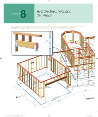
  • 1. Figure 8.1  The La Chapelle floor plan represents real framing to carpenters who read, visualize, and build from a set of plans. Architectural Working Drawings 8 Chapter M08_POWE4171_01_SE_C08_074-093.indd 74 12/4/14 4:03 PM
  • 2. Chapter 8 Architectural Working Drawings     75 Variation on framing for La Chapelle Plan Set Plan M08_POWE4171_01_SE_C08_074-093.indd 75 12/4/14 4:03 PM
  • 3. 76    section Three  Project Planning and Architectural Plans O b j e c t i v e s Architectural Plans and Plan Sheets Contract-related documents include the final building contract, detailed specification sheet(s), and working drawings for con- struction. This set of paperwork becomes part of the legal founda- tion for the project. Each document is vital to the building process. The various plan sheets listed below make up the working draw- ings that builders and subcontractors typically use to develop their estimates. Carpenters will use the same drawings to interpret the design and build the structure. Many people refer to a set of working drawings as plans or blueprints. In fact, working drawings are part of the complete set of architectural plans. Architectural plans include working drawings, schedules, and other sheets shown in the list below. Many architectural plan sheets are horizontal (section) views of the building. The most common plan sheets include floor plans, foundation plans, and roof plans. The order of plan sheets gen- erally follows the order of the building process. Elevation views are usually before building plans to give builders, homeowners, and trade workers a sense of how the entire project will look on completion. Not all architectural plan sets will include each sheet listed below. 1. Title and Legend Sheet(s) 2. Plot Plan (site plan) 3. Elevations 4. Foundation Plan 5. Floor Framing Plans 6. Floor Plans 7. Ceiling Framing Plans 8. Roof Framing Plans 9. Window and Door Schedules 10. Details and Section Views 11. Interior Elevations 12. Trade Plans (Mechanical, Electrical, Plumbing) 13. Specifications The sophistication and detail in a set of construction plans may vary based on building design, owner’s need, and the ar- chitect. In any case, enough detail is required to help minimize mistakes and facilitate coordination within the various trades, subcontractors, and materials suppliers. In drawing construction plans, architects, drafters, or builders will illustrate many details in only one place to eliminate confusion and redundant informa- tion. For instance, specifying the same stud spacing on every wall section is not required for most plans. Title Sheets The title sheet (Figure 8.2) is the cover for a set of architec- tural plans. On new construction, the title sheet typically has a front elevation view of the home. The title sheet normally includes all pertinent information about the primary parties involved with the project. The title sheet will list the architect (designer), owner, builder, and major subcontractors, and it may include a green home certification program’s seal and the green verifier’s information. Other sheets in the plan set will use a title block. The title block organizes some of the same information from the title page for quick reference on each page. Page numbers will be part of a title block to help keep drawings organized. Plan Visualization Visualizing the finished home or addition by reviewing a set of working drawings is a learned skill developed by builders, car- penters, and other craftspeople. It takes practice to develop the spatial skills necessary to visualize a three-dimensional building represented on a two-dimensional sheet of paper. Experienced carpenters can take a virtual tour in their minds of the finished building as they read and interpret information in a set of ar- chitectural plans. As this chapter covers each plan sheet, draw a mental picture to visualize the information and begin developing spatial skills. Figure 8.1 illustrates how the 2-D drawing becomes a real 3-D structure. Orthographic Projection Drafters, engineers, architects, and builders use a system known as orthographic projection to create drawings of three-dimensional buildings on two-dimensional paper. Ortho means “straight line” and this projection provides a graphical representation on a two-dimensional plane. The projection represents objects drawn with a common relationship; that is, they are in scale with each other. Common perspectives and drawing techniques are shown in Figure 8.3. Acommondrawingperspectiveprovidingathree-dimensional view (3D) is the isometric view. Isometric views place all horizontal lines at 30° angles relative to the horizon with vertical lines perpen- dicular to the horizon. With this method, all lines are to scale and remain in proportion. An example is shown in Figure 8.3. n Define and explain the various sheets that make up a set of architectural plans. n Identify the sheets in a set of working drawings and ex- plain the information available from each working drawing. n Define the most common scales used on architectural plans. Explain why scales are important and what informa- tion they make possible on a single plan sheet. n Give examples of electronic plan scaling aids and software available to estimators and builders. Explain how these tools help estimators work faster and more accurately. n Explain why section views and details are important plan sheets. How do carpenters and other trade workers use these views? n Explain how Building Information Modeling software helps build energy-efficient homes. M08_POWE4171_01_SE_C08_074-093.indd 76 12/4/14 4:03 PM
  • 4. Chapter 8 Architectural Working Drawings     77 LICENSED LAND SURVEYOR CODE ENFORCEMENT PLAN REVIEW APPROVAL ONE STORY RANCH W/ DETACHED GARAGE COVER SHEET & SITE PLAN W. KEITH POWELL N 02°00'00" E 105.97' S 05°0 0'00 " W 158 .12' N 7 0 °0 0 '0 0 " W 1 1 1 .0 9 ' S 20°00'00" W 114.52' 12'-0" WIDE ASPHALT TRAVEL LANE (60' PUBLIC RIGHT-OF-WAY) 4'-0" WIDE BIKE LANE 2' WIDE GRAVEL SHOULDER 8' WIDE UTILITY EASEMENT 33.14' 47 .2 8' 17.70' 25' FRONT BUILDING SETBACK LINE 15' SIDE BUIL DING SETB ACK LINE 15' SIDE BUILDING SETBACK LINE 25' REAR BUILDING SETBACK LINE 2' WIDE GRAVEL SHOLDER SAN SAN SAN G W S SL SL G S G S SL W S W S G G G G E E E E E W W W 4'-0" PUBLIC SIDEWALK S 05°00'00" W 156.29' PROPERTY BOUNDARY LINE 10' 88 .5 ' 10' MIN. BENCHMARK “X” ON TOP OF CONCRETE HIGHWAY MONUMENT ELEV. = 100.00 0 20 40 SCALE IN FEET 1” = 120’ SITE PLAN SITE LOCATION MAP SHEET INDEX SAWYER LANE SAWYER LANE M c M U R R Y W A Y 1 STORY WOOD FRAME HOUSE 1,987 S.F . SUB-FLOOR ELEV. = 106.32 10’ WIDE DRIVEWAY W/ TURN-AROUND SEE NOTE 3 FOR OPTIONAL SURFACES D R IV E W A Y DRIVEWAY MAY ALSO BE USED AS CONSTRUCTION STAGING UNTIL CONCRETE IS PLACED AND FINISHED LOT AREA = 26,548 S.F . / 0.61 ACRES PROPERTY BOUNDARY C1 A1 A2 A3 A4 A5 A6 A7 S-1 D-1 D-2 D-3 COVER SHEET, SITE PLAN SOUTH & EAST ELEVATIONS NORTH & WEST ELEVATIONS FOUNDATION PLAN FIRST FLOOR FRAMING PLAN FIRST FLOOR PLAN CEILING FRAMING PLAN ROOF FRAMING PLAN CROSS SECTIONS & INTERIOR ELEVATIONS DETAILS DETAILS DETAILS WINDOW SCHEDULE A B C D E F G H I J K L M N O P Q R MODEL MARK (3) 3056DH/TR 3060DH/TR 2630DH (2) 2030DH/TR (3) 4050DH/TR (2) 2056DH/TR 6010TR (3) 3050DH/TR 2040GL/TR 4010TR 2050DH/TR (2) 3050DH/TR 2630DH/TR 4050DH/TR 28110AW 2650DH CUSTOM SK CUSTOM SK 42.75 14.25 5.62 13.5 17.25 10.5 4.20 40.5 8.25 3.00 9.75 27.0 7.87 17.12 3.73 9.37 8.00 16.00 19.44 6.04 3.50 8.43 8.10 4.55 - 18.22 3.24 - 4.05 12.15 3.5 7.11 3.49 6.75 2.00 NA 9'-0 1/2" × 6'-6 1/2" 3'-0 1/2" × 7'-0 1/2" 2'-6 1/2" × 3'-0 1/2" 4'-0 1/2" × 4'-0 1/2" 4'-0 1/2" × 6'-0 1/2" 2'-0 1/2" × 6'-6 1/2" 6'-0 1/2" × 1'-0 1/2" 9'-0 1/2" × 6'-0 1/2" 32 1/2" × 27" (6.04) M. BDR. 32 1/2" × 27" (6.04) BDR. 2 41 7/8" × 28" (7.63) BDR. 3 2'-0 1/2" × 5'-0 1/2" 4'-0 1/2" × 1'-0 1/2" 6'-0 1/2" × 6'-0 1/2" 6'-0 1/2" × 6'-0 1/2" 2'-6 1/2" × 4'-0 1/2" 4'-0 1/2" × 6'-0 1/2" 2'-8 1/2" × 1'-10 1/2" 2'-6 1/2" × 5'-0 1/2" 2'-0" × 4'-0" Per P .E. 4'-0" × 4'-0" Per P .E. DH = DOUBLE HUNG, TR = TRANSOM, CS = CASEMENT, GL = GLIDER, AW = AWNING, SK = SKYLIGHT SYMBOL COMMERCIAL (RETAIL, RESTAURANTS, COMMUNITY SERVICES) DELLA’S PLACE COMMUNITY PARK SITE INFILL LOT A ROUGH OPENING WIDTH × HEIGHT LIGHT S.F . VENT. S.F . EGRESS W. × H. (S.F .) LEGEND LAND CONSERVATION AREA SEE NOTE 1 DECK RAIN GUTTER DOWNSPOUT LOCATION (3 TYP .) ROOF OVERHANG ROOF OVERHANG X X X X X X X X X 14'-6" 22'-0" 22'-0" 26 '-0 " 26 '-0 " 32'-10" 15'-0" 2' CANTILEVER STEPS STEPS SIDEW AL K 8'-91/ 8" STEPS 10'-8" 30'-0" 18'-0" 17'-0" 8'-0" 32'-0" 33'-0" 10'-0" PORCH CONSTRUCTION STAGING AREA SEE NOTE 2 LAWN AREA SEE NOTE 4 PATIO LIMITS OF CLEARING LIMITS OF CLEARING CONSTRUCTION / SILT FENCE LAWN AREA SEEN NOTE 4 WOODED AREA WOODED AREA WOODED AREA CURB STOP WOODED AREA LAWN AREA SEEN NOTE 4 2 CAR GARAGE SITE PLAN NOTES: 1) AREA RESERVED FOR LAND CONSERVATION: A) THE GENERAL CONTRACTOR SHALL INSTALL AND MAINTAIN A CONSTRUCTION (SILT) FENCE AS SHOWN. FINAL PLACEMENT BY EPA CERTIFIED ENGINEER, POSSIBLE SITE RETENTION POND PER LOCAL REQUIREMENTS. B) SILT FENCES AND/OR HAY BALE DYKES SHALL BE INSTALLED AS PER CIVIL ENGINEER’S INSTRUCTIONS TO PROVIDE SOIL AND SEDIMENT CONTROL. 2) THE CONTRACTOR SHALL CONTAIN STAGING, STOCKPILE, AND DISPOSAL ONLY WITHIN THE DESIGNATED AREA. 3) OPTIONAL SURFACES FOR DRIVEWAY AND SIDEWALKS: PERVIOUS CONCRETE, RECYCLED ASPHALT/RUBBER; GRAVEL; CRUSHED STONE, BRICK, SEA SHELL, OR OTHER REGIONALLY AVAILABLE RE-PURPOSED MATERIALS. PROTECT EXISTING PUBLIC SIDEWALK DURING CONSTRUCTION. 4) ALL LAWN AREAS SHALL RECEIVE FINAL GRADING AND SEEDING AS SOON AS POSSIBLE AFTER CONSTRUCTION IS COMPLETE. LAWN OPTIONS; PLANNED NATURAL AREAS AND XERISCAPING WITH GRASSES AND WILD FLOWERS ACCUSTOMED TO LOCAL CONDITIONS AND YEARLY RAINFALL TO MINIMIZE WATER USE FOR IRRIGATION. SITE STATISTICS: LOT AREA: 26,548 S.F . / 0.61 ACRES DEDICATED GREEN SPACE: 6,674 S.F . / 25% BUILDING SIZE: 1,987 S.F . GARAGE SIZE: 272 S.F . TOTAL IMPERVIOUS AREA: 2,259 S.F . / 9% PERVIOUS CONCRETE AREA: 1,053 S.F . / 4% BUILDING SETBACK LINES UTILITY EASEMENT LAND CONSERVATION BOUNDARY ROOF GUTTER & DOWNSPOUT CONSTRUCTION FENCE GAS MAIN GAS SERVICE G U.G. ELECTRIC E GS W WS 99 SAN SL SANITARY SEWER SANITARY LATERAL WATER MAIN WATER SERVICE ES ELECTRIC SERVICE GROUND ELEVATION CONTOUR LIMITS OF CLEARING ES ES RESIDENTIAL SUBDIVISION INFILL LOTS EARN GREEN CERTIFICATION POINTS 12 10 8 23 25 21 19 GREENWAY AREA, OLD RAILROAD REMOVED R310.1.1 MINIMUM OPENING AREA. ALL EMERGENCY ESCAPE AND RESCUE OPENINGS SHALL HAVE A MINIMUM NET CLEAR OPENING OF 5.7 SQUARE FEET. (EXCEPTION: GRADE FLOOR OPENINGS SHALL HAVE A MINIMUM NET CLEAR OPENING OF 5 SQUARE FEET). R310.1.2 MINIMUM OPENING HEIGHT. THE MINIMUM NET CLEAR OPENING HEIGHT SHALL BE 24 INCHES. R310.1.3 MINIMUM OPENING WIDTH. THE MINIMUM NET CLEAR OPENING WIDTH SHALL BE 20 INCHES. R310.1.4 OPERATIONAL CONSTRAINTS. EMERGENCY ESCAPE AND RESCUE OPENINGS SHALL BE OPERATIONAL FROM THE INSIDE OF THE ROOM WITHOUT THE USE OF KEYS, TOOLS OR SPECIAL KNOWLEDGE. ENERY SPECIFICATIONS Design U-Factor = 0.35 Design SHGC = 0.40 U-VALUE AND SOLAR HEAT GAIN COEFFICIENT (SHGC) MINIMUMS PER CLIMATE ZONE 3A EMERGENCY EGRESS SIZE 2-2×4 2-2×6 2-2×8 2-2×10 2-2×12 3-2×8 3-2×10 3-2×12 4-2×8 4-2×10 4-2×12 GROUND SNOW LOAD (PSF) = 30 BUILDING WIDTH = 36' SOURCE: 2015 IRC TABLE 602.7(1) SPAN 2'-10" 4'-2" 5'-4" 6'-6" 7'-6" 6'-8" 8'-2" 9'-5" 7'-8" 9'-5" 10'-11" NO. JACK STUDS 1 1 2 2 2 1 2 2 1 2 2 FOOTNOTE D, TABLE 602.7(1); “WHERE THE NUMBER OF REQUIRED JACK STUDS EQUALS ONE, THE HEADER IS PERMITTED TO BE SUPPORTED BY AN APPROVED FRAMING ANCHOR . . .” SL. = SLIDER, BF = BI-FOLD DOOR SCHEDULE 1 2 3 4 5 6 7 8 9 10 SIZE MARK 3 1 " " " " " " " " " 0 68 3 4 STL. INS. STL. INS. F .G. INS. H.C. WD. H.C. WD. H.C. WD. H.C. WD. H.C. WD. PC. SL. HG. HG. HG. HG. HG. HG. HG. B.F . H.C. WD. EXT. EXT. EXT. INT. INT. INT. INT. INT. INT. × × 13 4 × 13 4 × 13 8 × 13 8 × 13 8 × 13 8 × 13 8 × 13 8 × 28 70 × 60 70 × " 13 4 × 30 70 × 28 70 × 20 70 × 28 70 × 16 70 × 40 70 × 30 70 × STL = STEEL, INS = INSULATED, S.G. = SAFETY GLASS, FG = FIBERGLASS, HC = HOLLOW CORE, WD = WOOD, HG. = HINGED, PC = POCKET, SYMBOL 1 MAT’L. 1" INS. ENTRY ENTRY ENTRY PRIVACY PRIVACY 1" INS. STL. INS. EXT. ENTRY 1" INS. 1" INS. S.G. GLASS LOCKSET TYPE INTERIOR EXTERIOR NOTE: HOME DESIGN IS TYPICAL FOR INTERNATIONAL ENERGY CONSERVATION CODE AND INTERNATIONAL RESIDENTIAL CODE CLIMATE ZONE 3A. GIRDER & HEADER SPANS FOR EXTERIOR WALLS (supporting Roof and Ceiling) Figure 8.2  Check the title sheet for contact information and other details. Figure 8.3  A full set of building plans will use many drawing types to relate information using 2D and 3D techniques. Front 30° 30° Right side ORTHOGRAPHIC PROJECTION Vanishing point Horizon line Vanishing point PERSPECTIVE ISOMETRIC M08_POWE4171_01_SE_C08_074-093.indd 77 12/4/14 4:03 PM
  • 5. 78    section Three  Project Planning and Architectural Plans Figure 8.4  Manual and electronic aids help estimate plans quickly estimator work quickly and accurately. Sources: (a, b, c) Alvin & Company, Inc.; (d) Scalex Corporation (a) Architect’s flat scale (c) Rolling ruler (d) Scalex PlanWheel (b) Architect’s triangular scale How to Apply the Architect’s Scale  Learning to use the architect’s scale is important to reading and interpreting working drawings. Follow the steps shown below and refer to Figure 8.7 to practice with an architect’s scale and develop accuracy and confi- dence in reading working drawings. The figure in this example is part of plan sheet A-5 the detached garage from the La Chapelle Plan But the technique can be used throughout any scaled set of plans using an architectural ruler. 1. Find the appropriate fraction mark at the end of the scale that corresponds to the scale of plan sheet A-5. In this example shown in Figure 8.7, 1>4″ = 1′ is used. 2. Using the 1/4″ scale, set the architectural ruler on the zero mark and one corner of the garage front. 3. Read across the scale to the other end of the garage and note 22′. 4. On a 1>4″ = 1′ scale, 5½″ is equal to twenty-two 1>4″ seg- ments; i.e., 22′ as shown on plan sheet A-5. Take a basic ruler and you will see the garage’s actual measurement on the plan sheet is 5½″. 5. The area to the right of the zero mark on the architect’s scale is for measuring inches. For example, you can meas- ure 9″ on the scale right of the zero mark by counting nine hash marks. Civil Engineer’s Scale On a building lot or larger land area, surveyors use measuring equipment that divides parts of a foot into a decimal number car- ried to thousandths of a foot for accuracy; for example, 255.469′ may be the length of a property line. Because of the larger scales, decimal formatting, and accuracy, surveyors use this standard to create the property lines on most plot plans. A civil engineer’s Dimensioning Aids for Working with Architectural Plans Reading a set of construction plans requires practice, experi- ence, and spatial skills. To quickly read rough dimensions or for estimating; a wide range of computer controlled, electronic, and manual dimensioning aids are available. Even though these tools usually provide enough accuracy for estimating and general draw- ings, always refer to the architectural plans for exact dimensions and details. Various scaling tools are available to increase accuracy and speed when estimating; see Figure 8.4. Architect’s Scale There are several versions of the architect’s scale; the most com- monly used is triangular with 11 different scales, one being a full-size ruler. Common plan scales are shown in Figure 8.5. The end of each scale has a fraction that designates the par- ticular scale. In residential construction, 1>4″ = 1′ is the most common scale used on working drawings, as shown in Figure 8.6. However, some plan sheets, depending on paper size, build- ing size, and objects represented, may use 1>8″ = 1′ or other scales. Be sure to check each sheet for the appropriate scale be- fore taking measurements. P r o f e s s i o n a l T i p Written plan dimensions always take precedence over scaled and measured dimensions. Variations in printing and paper can decrease the accuracy of measuring and scaling dimen- sions from a physical plan set. M08_POWE4171_01_SE_C08_074-093.indd 78 12/4/14 4:04 PM
  • 6. Chapter 8 Architectural Working Drawings     79 3" = 1' 0 1 2 3 4 5 6 7 8 9 10 11 12 3 16 12" = 1' full scale; (also use 1/16" = 1') Yellow mark = one scaled foot 0 1 2 3 11/2" = 1' 9 2 1 6 3 0 2 1 1 1" = 1' 0 3 6 9 1 2 3/4" = 1' 4 3 0 3 1 2 2 1 1/2" = 1' 0 2 4 3/8" = 1' 0 2 4 6 8 3 32 3 1/8" = 1' 8 1 3/32" = 1' 3/16" = 1' 0 4 8 12 16 20 24 28 32 0 2 4 6 8 10 14 16 16 3 4 1 0 4 8 12 16 20 24 1/4" = 1' 0 2 4 6 8 10 Figure 8.5  Eleven scales are available on a triangular architect’s ruler. The most common used in residential construction is 1/4″ = 1′. scale can be used to read these large-scale drawings easily. The civil engineer’s scale divides into six scales; each scale further mul- tiplies by a factor of 10 for increasingly larger scale drawings. See the engineer’s scale chart and example for reading a civil engineer- ing scale in Figure 8.8. Electronic Scaling Tools Electronic tools are available for scaling plans when estimating. Two popular types, the ScaleMaster II and the Scalex PlanWheel (shown in Figure 8.4), can perform linear, area, and volume measurements for easy and accurate estimating. Some electronic measuring aids are wireless and interface with spreadsheets and estimating software. Some versions have a small calculator built in to help with adding and subtracting measurements. All dimen- sioning aids help with calculations required for estimating. In ad- dition, electronic aids increase accuracy to a higher level and can decrease overall estimating time. Working Drawings Depending on building complexity, roof design, and other vari- ables, a set of working drawings for a residential home may be 5 to 10 sheets. For basic designs, a simple floor plan, a few speci- fications, and possibly a roof plan is all many carpenters need once the building corners are determined with a site plan. The point is that working drawings may be very simple or very com- plex depending on the project and the experience level of the builder and crew members. Using the International Residential Code, experienced carpenters can easily adjust to a particular set of working drawings. The complexity of the drawing is a factor in determining the plan sheet size; standard sizes are shown in Figure 8.9. The working drawings provided to contractors for bidding serve many purposes in the overall construction process. Below are some applications of working drawings other than physical construction. 1. Estimating and Take-offs. The builder and subcontractors use working drawings to calculate all of their materials, labor, and other expenses. 2. Permitting. In residential construction, the requirement for plans in the permitting process varies by jurisdiction. Some architects create a set of plans specifically for permitting; they may have a slightly different look than actual working draw- ings. 3. Permanent Record. A set of working drawings constitutes a permanent record of construction and design, along with all details and specifications. Provide a set to the homeowner for future repairs, additions, or remodeling projects. 4. Legal Record. The working drawings become part of the le- gal record for the building. If legal issues arise during or after construction, courts may use working drawings as a basis for determining important facts. M08_POWE4171_01_SE_C08_074-093.indd 79 12/4/14 4:04 PM
  • 7. 80    section Three  Project Planning and Architectural Plans Using the common 1" = 1" scale, the master bedroom’s physical measurement is 45/8". Using the 1/4" plan scale converts it to the actual size of 18'-5". La Chapelle House Plan Figure 8.6  Scaled drawings help to illustrate an entire building on a single plan sheet. 3 1 2 5 4 Figure 8.7  Using the scales on an architectural ruler, a carpenter, builder, or designer can draw large-scale areas on plan sheets. M08_POWE4171_01_SE_C08_074-093.indd 80 12/4/14 4:04 PM
  • 8. Chapter 8 Architectural Working Drawings     81 Presentation and Elevation Viewing Style Presentation View Plan books, internet sites, architects, or builders may provide a presentation view (Figure 8.10). This is essentially a tool for selling the plans or home and provides little related to actual construc- tion detail. Presentation views, in pencil or color, typically show fully developed landscaping, distinctive features, and even people to present the finished home in a favorable light. Unless the owner specifically requests the added perspective provided by a presenta- tion drawing, it is not included in most construction plans. Whole House Elevation Views Elevation views provide a visual and scaled view of the home’s exte- rior or interior. Most plan sets include views with each side shown and detailed. Elevations include references to many specifications for framing and exterior finishes. Roof slopes, ceiling heights, finished floor heights, and roofing and siding materials are usually identified on elevation sheets, as shown in Figure 8.11 and detailed as follows: Roof slope: Roof slopes may not be the same for all covered sections of the home. For example, dormers, shed roofs, and garages may have different slopes. Ceiling heights: Ceiling heights are provided on most elevation sheets and may be included on specifications or detail sheets. Exterior finishes: Exterior finishes are usually illustrated and noted on elevations. In some cases, the street side of a home will be brick and the other three sides are covered with siding or other materi- als to meet restrictions of the neighborhood or community. Topography: The actual lot grade (topography) helps estimators calculate foundation materials and grading work. Elevations also illustrate the home’s finished look in relation to grade. Interior Elevations Interior finish work such as cabinets, trim work, and built-in bookcases may have a plan sheet (see Figure 8.12) with interior elevations so carpenters know where to set these items. Interior elevations dimension universal design features like lowered counters or fixtures so carpenters can install the features ac- cording to requirements. Universal design heights and details for doors, cabinets, and other features are discussed in other ar- eas of the text. Layout and Framing Plan Views For plan views, a cutting plane is a horizontal line “cutting” the object for a better view. For example, with typical floor plans, the horizontal cutting plane is typically at a height that cuts through doors and windows on exterior walls so they are in the final view. Removing the area above the cutting plane creates a bird’s-eye view looking down into the structure like the example in Figure 8.13. Plot or Site Plan A site plan (Figure 8.14) contains information verified by a sur- veyor, engineer, and others. It illustrates important features such as utility easements, topography, property lines, setbacks, and el- evations. Site plans usually include the building footprint, drive- ways, auxiliary buildings, and other constructed features on site as references. A plot plan, very similar to a site plan, is specifically for recording a piece of land and shows much of the information on the site plan without a house on the lot. Some of the important aspects include the following: Easements: Any property easements must be specifically located and identified. It is advisable to check with code officials and utility companies for restrictions and setbacks related to prop- erty easements. Setbacks: All property setbacks shown on site plans should be verified with local zoning officials before construction begins. A quick phone call can help eliminate serious code problems related to building within a setback area. Benchmark: The benchmark sets the elevation of many con- struction features, including finished floor levels and founda- tion heights. Site plans contain very important information about el- evation. Each site plan has an elevation called the benchmark. The benchmark represents a starting elevation that may be an actual elevation above sea level or, for ease of use, an arbi- trary number like 100.00′. In either case, all points of eleva- tion throughout the site plan reference against the benchmark elevation. Carpenters and masons will use these elevations as starting points to calculate foundations and finished floor heights. Masonry workers will use these elevations to build and check all foundation walls, piers, and other structural compo- nents of the foundation system. Site or plot plans have become more significant in today’s environment of green building. The orientation of the building is important to operating efficiency. Windows and doors can be oriented and sized to maximize any solar advantages based on the home’s location. The site plan can be used to manipulate the scaled building footprint into the best orientation for solar ef- ficiency based on location, building size, and limitations of the building lot. These plan sheets also show protected areas like tree drip zones and natural areas, as well as areas designated for mate- rials storage and heavy equipment. P r o f e s s i o n a l T i p The oldest known plan or drawing dates back to around 2100 BC and is credited to the Chaldean Prince of Lagash, a city-state in ancient Mesopotamia. In his time, the prince was known as an engineer and a builder. M08_POWE4171_01_SE_C08_074-093.indd 81 12/4/14 4:04 PM
  • 9. 82    section Three  Project Planning and Architectural Plans Foundation Plan The information on a foundation plan provides critical dimen- sions for structural support features. The height of the cutting plane should be set to “cut through” any windows, doors, or other openings in basement walls so the builder can define locations, Figure 8.8  Civil engineering scales are designed for working with very large distances. 30 1" = 30' 0 20 10 / 1 to 1 20 / 1 to 2 30 / 1 to 3 40 / 1 to 4 50 / 1 to 5 60 / 1 to 6 1" = 1' 1" = 2' 1" = 3' 1" = 4' 1" = 5' 1" = 6' 1" = 10' 1" = 20' 1" = 30' 1" = 40' 1" = 50' 1" = 60' 1" = 100' 1" = 200' 1" = 300' 1" = 400' 1" = 500' 1" = 600' Scale Division/Ratio Multiply Scale by Factor of 10 for Larger Scale Civil Engineer’s Scale (also commonly used by surveyors) 40 60 8.5" × 11" A B C D E 11" × 17" 17" × 22" 22" × 34" 34" × 44" Figure 8.9  The American National Standards Institute (ANSI) de- veloped a standard for working drawings using a letter designation corresponding to each sheet size. Large size E prints provide the most detail and are easier to read. Figure 8.10  Presentation drawings are used to present the finished home in the best light possible for selling sets of plans or the proposed new home. 1, , , 1, 1, 1, 1, 1 1 1 1 1 1, 1, 1 1 1 1 1 1 1 1 1 1 1 1 1 1 1 1 1 1 1 1 1 1 1 1, 1, 1 1 1 1 1 1, 1 1 1 1, 1 1 1, 1 1, 1 1 1, 1 1 1, 1 1 1 1 1 1 1, 1, 1 1 1 1 1 1 1 1 1 1 1 1 1 1, 1 1 1 1 1 1 1, 1 1 1 1 1 1 1 1 1 1 1 1 1 1 1 1 1, 1 1 1 1 1 1 1 1 1 1 1 1 1 1 1 1 1 1, 1 1 1 1 1, , 1 1 1 1, 1 1 1 1, 1 1 1 1 1 1 1 1 1 1, ,98 98 987 7 7 Sq Sq Sq q. . F Ft Ft. Ranc nc nch h h on on n 0 0 6 .6 .6 .61 1 1 1 Ac Ac Acre re res s s 3 3 3 3 3 3 3 3 3 3 3 3 3 3 3 3 3 3 3 3 3 3 3 3 3 3 3 3 3 3 3 3 3 3 3 3 3 3 3 3 3 3 3 3 3 3 3 3 3 3 3 3 3 3 3 3 3 3 3 3 3 3 3 3 3 3 3 3 3 3 3 3 3 3 3 3 3 3 3 3 3 3 3 3 3 3 3 3 3 3 3 3 3 3 3 3 3 3 3 3 3 3 3 3 3 3 3 3 3 3 3 3 3 3 3 3 3 3 3 3 3 3 3 3 3 3 3 3 3 3 3 3 3 3 3 3 3 3 3 3 3 3 3 3 3 3 3 3 3 3 3 3 3 3 3 3 3 3 3 3 3 3 3 3 3 3 3 3 3 3 3 3 3 3 3 3 3 3 3 3 3 3 3 3 3 3 3 3 3 3 3 3 3 3 3 3 3 3 3 3 3 3 3 3 3 3 3 3 3 Be B Be Be Be Be Be Be Be Be Be Be B B Be Be Be e Be Be B Be Be e e Be Be Be Be Be Be Be e Be Be Be B Be Be Be Be e Be Be Be Be B B B Be B Be B B B B Be e Be e e B Be B B B Be e e e B Be B Be e e B Be e e e B B B Be e Be Be e e e Be Be B B B B B Be e e e e e e Be B Be e e e Be e e e B B Be e e Be e e Be e e B B B Be e e e e e B Be e Be e e Be e e e B B B B B Be Be e e Be e e B Be Be B Be e e Be B Be B B B Be e e B B B Be e e B B Be B Be e e e e e e e e B Be e e e e e B Be e Be e e e e B B Be e e e B B B Be e e B B B Be e e e ed d d dr d d d d d d d d d d d d d d d d d d d d d d d d d d d d d d d d d d d d d d d d d d d d d d d d d d d d d d d d d d d d d d d d d d d d d d d d d d d d d d d d d d d d d d d d d d d d d d d d d d d d d d d d d d d d d d d d d d d d d d d d d d d d d d d d d d d d d d d oo oo om m ms 2 2 2 2 2 2 2 2 2 2 2 2 2 2 2 2 2 2 2 2 2 2 2 2 2 2 2 2 2 2 2 2 2 2 2 2 2 2 2 2 2 2 2 2 2 2 2 2 2 2 2 2 2 2 2 2 2 2 2 Ba B Ba Ba Ba B Ba Ba B Ba Ba B B Ba B Ba B Ba Ba B B Ba Ba B Ba Ba Ba Ba Ba Ba B Ba Ba B B B B B B B B Ba Ba Ba B B Ba Ba Ba Ba B B B B B B Ba Ba Ba Ba Ba Ba B B B B B B Ba B Ba B B B B B B B Ba B Ba Ba Ba B B B Ba a Ba a Ba Ba Ba Ba B Ba Ba B B B B Ba a Ba B B Ba Ba a a Ba a B B Ba Ba a a a a a Ba a B B B B Ba a a Ba a B B B B Ba a Ba Ba a a Ba B B B Ba a a Ba a a a a a a Ba a a a B Ba B B Ba a a a a a B Ba Ba Ba Ba Ba Ba Ba B B Ba a Ba Ba B B B Ba Ba a a B B Ba Ba Ba B Ba Ba a a a B B B B B Ba B B Ba a a a Ba Ba a a Ba a Ba B Ba B Ba a a a a Ba B B B B Bath th th th t th th th th th t t t t t t t th th t t t th t th th th th th th th t th t t t t t t t t t t t t t t th t t t t t th t t t t t th h h h h h h h th h th h h th h h h h h t t t th h th h h h h h h h h t t t th h h h h h h h th h t t t th t th t th h h h h h th t t t t th h h h h h h t th th h h h t t t t t t t t s s s s s s s s s s s s s s s s s s s s s s s s s s s s s s s s s s s s 2 2 2 2 2 2 2 2 2 2 2 2 2 2 2 2 2 2 2 2 2 2 2 2 2 2 2 2 2 2 2 2 C C Ca a a Ca C Ca Ca Ca Ca Ca Ca a C Ca C Ca C Ca C Ca Ca C Ca a Ca Ca C Ca C C Ca Ca Ca Ca Ca C C C C C Ca Ca C Ca Ca a Ca Ca C C C Ca a Ca Ca C Ca a Ca C Ca C Ca Ca Ca Ca Ca Ca a Ca Ca Ca C Ca a a a Ca Ca a a a a a a C C Ca a a a C C Ca C C C Ca C C C Ca C C Ca a a a a a a a a a Ca a a a a a C C C C C C Ca C C C C C r r r r r r r r r r r r r r r r r r r r r r r r r r r r r r r r r r r r r r r r r r r r r r r r r r r r r r r r Ga G G Ga Ga Ga Ga Ga G G Ga Ga Ga Ga Ga G Ga G Ga G Ga G Ga Ga G Ga G G Ga Ga Ga G G G Ga Ga Ga G G G G Ga Ga Ga Ga Ga Ga Ga G G Ga G G Ga G G Ga Ga Ga Ga Ga G G G G G G G Ga G G G Ga a Ga G G G G Ga G G G Ga Ga Ga G Ga Ga G G Ga a a G G Ga G G G G G G G Ga G G Ga Ga G G G G G Ga G G Ga G G G G G Ga G Ga G G Ga G G G Ga G G G G G G Ga G G Ga Ga a a a Ga G G G Ga G G G Ga a a a a a G G G G G Ga G Ga a a a a a a a a G G G G G Ga a a a a a a a a a a a a a G G G G G G Ga a a a a a a a a Ga a Ga Ga a a a Ga a a Ga G G G G G G G G G G G G Ga G G G G G G G G G Ga G G G G Ga G G G Ga a G G G Ga G G Ga a G G Gara r r r r r r r r r r ra r r r r r ra r r r r r r r r r r r r r r r r r r r r r r r r r r r r r r r r r r r r ra r r r ra r r r r ge ge ge ge ge g g So So So So o S So So So So So So So So So S S So So So S So S S S So So S So So So So So S S So So o S So S S S S S S S So So S So So o o S So o o o So o So o o o o So So o o o S S So o S S S S So o So o o o o o o o o o o o o ola la la la la la la la l la la a la a la la la la la a la la a a la a la la l la l la a a a a a a a a ar r r r r r r r r r r r r r r r r r r r r r r r r r r r r r r r r r r r r r r r r r r r r r r r r r r r r r r r r r r r r r r r r r r r r r r r r r r r r r r r r r r r r r r r r r r r r r r r r r r r r r r r r r r r r r r r r r r r r r r r H Ho Ho Ho Ho H Ho H Ho Ho Ho Ho Ho Ho Ho Ho Ho Ho Ho Ho Ho o Ho o o Ho o H H Ho Ho H Ho Ho o Ho Ho H H Ho H Ho Ho o H H H H H H Ho o o Ho Ho Ho H H H H Ho Ho H H H H H H Ho Ho Ho Ho Ho o o H H H H H Ho Ho Ho Ho H Ho o o Ho o H H H Ho Ho H H H Ho Ho o o o o o o H H Ho o Ho Ho o o Ho o Ho o o o Ho o Ho o Ho o o Ho H Ho Ho Ho o Ho Ho o Ho H Ho Ho Ho Ho H Ho o Ho o H Ho o o o Ho H H Ho H Ho o Ho Ho Ho o Ho H Ho H H Ho Ho Ho Ho H H Ho Ho Ho H Ho o Ho Ho H Ho H H H H Ho o H Ho o o o o o o o o o o H Ho o o o o o o ot t t t t t t t t t t t t t t t t t t t t t t t t t t t t t t t t t t t t t t t t t t t t t t t t t t t t t t t t t t t t t t t t t t t t t t t t t t t t t t t t t t t t t t t t t t t t t t t t t t t t t t t t t t t t t t t t t t t t t t t t t t t t t t t t t t t t t t t t t Wa Wa W W W W W W W W W W W W W W W W W W W W W te te te te ter r r r r Ph Ph Ph Ph Ph Ph Ph Ph Ph Ph Ph Ph h Ph h Ph Ph h Ph Ph Ph h h Ph h h h h h P Ph h h Ph h h h h h h h h h h h h h h h h h h Ph Ph h h h h Ph h Ph Ph h P P ot ot ot ot ot t t t t t t ot ot ot t t t t t t ot o ot ot t t t ot t ot ot o ot t t t ot o o ot t ot o ot o ot ot o ot ot t ot t t t t t t t o ot o o otov ov ov ov ov ov ov o o ov ov ov ov ov ov ov ov o o ov ov ov ov ov ov ov o ov ov o o o ov o ov ov o ov o o ov o o o o o o o o o ov ov ov o o o o o o o o o o o o o ol o ol ol ol ol l ol ol ol l o ol l o o ol l ol l l ol l l ol l l o o ol o o ol o ol o o o ol ol o o o o o o o o o o o ol o o ol l ol o o o o o o ol o o ol o o o o o ol ol ol ol ol o o o o ol ol ol o ol o o ol l l ol ol l o ol o o o o o o o o o o o o o o o ol o o o o o o o ol o o o o o ol o ol l l o o o ol l l o o o o ol o o o o o t t t t ta t t t ta ta t t t ta t t t ta t ta t t t t t ta ta ta t ta a ta ta ta ta ta ta ta a a a a t ta ta ta ta a a ta a ta ta ta a a a a ta ta a ta ta a a a a t t t ta t ta t t t ta a a ta a t t t t t t ta ta a a a t t t ta t t ta a a t ta a a a a ta a ta a a a a a a a a a a a aic ic ic ic i S S S S S S S S Sup up p p p p p p p p p p p up p up p up up up up up up up up u u u u u u u u u up up u up up up p p p up up up up p up p p p up u u up p u u u u u u up p p p p p p p p p p p p p p p p p p p p p p p p p p p p ppl pl pl l l pl pl pl pl l l l pl pl pl p pl l l l pl pl pl l l pl pl l p pl pl l l l l pl l l l l l pl pl l l l pl pl pl pl p p pl p p p p pl p p pl l p pl p p p pl p pl p pl l l pl l l l p p p p p pl p p pl p p p pl p pl l pl pl p p p p p p p p pl pl p p p pl pl pl p p p pl p pl pl p p p p p pl pl p p pl p p pl p p pl p p p pl pl p p p p pl p p p pl p p pl p pl l p pl l pl p pl p pl pl pl p p pl l l pl p p pl pl l pl pl l p pl l p pl p p p pl l l p p p p pl l l p p p p p p p p p p p p p p p p p p p p p p p p p p p p p p p p p p p e em em em em em em em em m em em em em em em em em em em e em em m m e em e em m m e e e e em e e em m m m e e e e em m e e e e em e e e e em m em em e e e e e e em e em e e e e em e e em e e e e e e em e e em m e e e em e e em m em m m m m m m m em m m e e e e e e e e e e e e e e e e e en en e en en en en en en en en e en en en en en en en en en en n en en en en en n en e e e en n en n en e en n n en e e e e en e e e en e e e e en e en en e en en n e en n en en n n n en en n n en n e e e en n n n n n e e en en e en n en n n en n n e ta ta ta ta ta ta ta a a a ta ta a ta ta ta a ta ta ta t ta a a a a t t ta ta a t t t ta t t ta ta ta ta t t t t t t ta ta t ta a a a a ta ta ta ta a a a a a a a a a a a a ta ta ta a ta a a a a a a a a ta ta a ta a a ta ta a a ta a ta ta a a a ta a a a ta a ta a a a ta a a ta a t ta a a a a a a ta a a a a a a a a ta a a a a a a a a a a a a a a a a a a a a a a a a a a a a a a ta a a a a a a ta a a a ta t t ta a a a tal l l l l l l l l l l l l l l l l l l l l l l l l l l l l l l l l l l l l l l l l l l l l l l l l l l l l l l l l l l l l l l l l l l l l l l l l l l l l l l l l l l l E E E E E E E El E E E E E E E E E E E E E E E E E E E E E E E E E E E E E E E E E E E E E E E E E E E E E E E E E E E E E E E E E E E E E E E E E E E E E E E E E E E E E E E E E E E El El E E E E E El E E E E E E E E E E E E E El E E E E ec ec ec ectr tr tri ic ic ic 1,987 Sq. Ft. Ranch on 0.61 Acres 3 Bedrooms 2 Baths 2 Car Garage Solar Hot Water Photovoltaic Supplemental Electric M08_POWE4171_01_SE_C08_074-093.indd 82 12/4/14 4:04 PM
  • 10. Chapter 8 Architectural Working Drawings     83 Ma t h T i p The footing projection is the width of the footing beyond the foundation wall, pier, or column. IRC R403.1.1 Minimum Size states, “Footing projections, P, shall be not less than 2 inches and shall not exceed the thickness of the footing.” (2015 IRC, p. 80) For the example in Figure 8.15, what is the total foot- ing width based on the footing projection and basement wall specifications? Answer: Foundation wall is 108″ concrete with an exterior footing projection of 34″ and an interior footing projection of 34″ = 16″ total footing width. type, and other specifics. Take a look at the information below and noted in Figure 8.15 of important specifications provided by foundation plans. Foundation wall type and width: The foundation width as determined by code or design may not be the same for all areas of the building. Window openings: Window type, size, and location may not be the same at all locations. Dimension lines: Carefully note dimension lines and their refer- ence points. They may represent the outside edge, the center- line, or the inside edge of the object referenced. Footings and piers: Dashed lines represent the footing width for foundation walls, piers, and columns. The footing width beyond the foundation wall, column, or pier on either side is the footing projection (see Figure 8.15). Concrete: Some concrete specifications may be listed on foun- dation plans, but refer to specifications sheets for all pertinent details. Local frost lines: The depth of footings below grade must be defined by local code jurisdictions based on local soil and weather conditions. In the International Residential Code, Table R301.2(1), footnote b states, “The jurisdiction shall fill in the frost line depth . . . with the minimum depth of footing below finished grade.” (2015 IRC, p. 29) The floor plan provides the information needed to estimate many materials like studs, drywall, doors, windows, and floor framing. Many plan sets include framing sheets for floors, walls, and ceilings as shown in the following sections. Although not re- quired, framing sheets help estimators work more accurately and help carpenters reduce material waste. Room size and layout: As with any dimension, be sure of the reference point so the actual work will match the floor plan. In rooms with appliances, bathroom fixtures, or other equipment, the point of reference for dimensions is critical to design. For example, the kitchen cabinets are often preordered based on floor plan dimensions. A mistake in reference point here during rough framing means the cabi- nets may not fit in the finished wall space. See Figure 8.17 and the examples of minimum spacing requirements from the International Residential Code Figure R307.1, Mini- mum Fixture Clearances. Always confirm that dimensions meet any local changes to the model code. Piers and columns: The surface contact area of support for framing materials over bearing supports (piers and columns) is regulated by IRC section R502.6.1. It requires floor joists ends over bearing support to lap a minimum of 3″ and requires the boards to be nailed with three 10d face nails. Plumbing fixtures: IRC Section R307, Toilet, Bath and Shower Spaces, specifies minimum spacing requirements for these fixtures. Reading the floor plans correctly while laying out the walls is critical to assure code-compliant spacing in all areas. Electrical and HVAC: Floor plans are used by trades work- ers to position outlets, switches, home integration systems, HVAC supply and return registers, and many other compo- nents of the home design. Exterior features: Floor plans dimensionalize the place- ment of decks, porches, garages, and other attached, exte- rior features. Depending on design, exterior features like decks may have details specified and illustrated on other plan sheets. Floor Plan Floor plans like the example in Figure 8.16 are usually the most information-packed of all plan sheets. Like the foundation plan, the floor plan cutting plane should be at a height that includes all window and door openings. This sheet defines the size and layout of all rooms and may include electrical, HVAC, and plumbing information. If the home design is more complex, however, elec- trical, HVAC, and plumbing may be on separate sheets to simplify the view and help eliminate mistakes and oversights during esti- mating and construction. Ma t h T i p A floor plan measures from edge to edge on the exterior. One exterior kitchen wall shows an outside dimension of 12′-8″. According to the specifications, all exterior walls are framed with 2 × 6 studs, 1>2″ gypsum board on the interior, and 1>2″ OSB sheathing on the exterior. Wall-to-wall, what is the maxi- mum width of the cabinet assembly? Given dimension is 12′-8″. Subtract the 2 × 6 wall thick- ness from both sides (5½″+5½″ = 11″). Subtract the gypsum board and OSB from both sides (1>2″+1>2″ = 1″ × 2 sides = 2″). Final answer: 12′-8″-11″-2″ = 11′-7″ maximum cab- inet assembly width. M08_POWE4171_01_SE_C08_074-093.indd 83 12/4/14 4:04 PM
  • 11. 84    section Three  Project Planning and Architectural Plans La Chapelle House Plan Figure 8.11  Elevation drawings may identify important framing and finish design requirements, such as roof slope. Framing Plans for Ceilings and Roofs Ceiling or roof framing plans provide details for all structural components and the layout spacing and arrangement of the sys- tem. For example, in Figure 8.18, spacing and framing details for all ceiling joists are noted on the ceiling framing plan (sheet A-6). In addition, the size and type of all materials is defined in the framing plan. A ceiling or roof framing plan (Figure 8.18) will show details of framing for green features such as I-joists, raised-heel trusses, engineered lumber, or recycled steel. These green and sustainable design options must be detailed for carpenters to follow the de- sign specifics. Estimators also need this information for bidding. Some of the green features on framing plans may be included on the specifications sheets. Without a framing plan, carpenters will design a ceiling or roofsystembasedontheIRCcoderequirementstoprovideacode- minimum system that meets all standards for safety. However, using the green features noted above will improve on the mini- mum design requirements of the International Residential Code and may reduce materials consumption. Detail and Section Views The detailandsectionviews provide very specific information about a particular construction or design feature. These views provide en- larged drawings to show specific details. To assure compliance with design and efficiency standards for the home, carpenters need de- tail sheets to define materials, techniques, and special applications. Detail and section views are often combined several to a sheet. When a particular area of a plan sheet has a corresponding al- phabetical or numerical indicator, refer to the detail sheets. This indicator directs the carpenter to a particular enlarged view on the detail sheet. For example, note the window flashing details from plan sheet D-1 in Figure 8.19. One of the most common detail views is a wall section. See Figure 8.20 for the wall detail from plan sheet D-1. Common prac- tice is to include one typical wall section and any details unique to the home’s design or special features. A wall section may include green features and framing requirements above code minimums as shown in Figure 8.20. Study detail sheets carefully before con- struction begins to assure compliance with structural, materials, and energy-efficiency requirements. M08_POWE4171_01_SE_C08_074-093.indd 84 12/4/14 4:04 PM
  • 12. Chapter 8 Architectural Working Drawings     85 La Chapelle House Plan Schedules and Specifications With a set of architectural drawings, the most common sched- ule or specification sheet is for windows and doors. Throughout a plan set, windows, doors, and other components have a numerical or alphabetical designator corresponding to an entry on the schedule sheet. Information on the schedule sheet will provide specifications, model numbers, material type, size, rough open- ings, manufacturer, and may include a notation of the product’s efficiency. See the window schedule from plan sheet C-1 in Figure 8.21. Chapter 43, Windows, Skylights, and Tubular Day-Lighting Devices, covers the efficiency standards noted on the C-1 plan sheet. CAD Programs for Design and Energy Efficiency CAD (Computer-Aided Design) software has been available for building design and estimating for years. Options range from simple to very sophisticated software and hardware packages for residential and commercial construction. The most advanced programs provide materials lists and 3D real-world walkthroughs and at the same time calculate the impact of materials and con- struction techniques on building operating efficiency. Stand- alone estimating and accounting programs are available as part of fully integrated modeling software called Building Information Modeling (BIM). BIM is sophisticated software that models many aspects of a building, including air quality, energy consumption, and operational efficiency. P r o f e s s i o n a l T i p CAD (Computer-Aided Design) or CADD (Computer-Aided Design and Drafting) are very similar. Both are available as freestanding programs or as part of a total BIM package. Figure 8.11  (Continued) 3D Design and Estimating Software Today’s estimating and 3D modeling software programs (resi- dential and commercial) range from entry-level programs to highly sophisticated custom programs. A basic example of what M08_POWE4171_01_SE_C08_074-093.indd 85 12/4/14 4:04 PM
  • 13. 86    section Three  Project Planning and Architectural Plans La Chapelle House Plan Figure 8.12  Elevations for interior work help carpenters meet layout and installation requirements. FLOOR PLAN 3D MODEL SHOWING CUTTING PLANE Cutting plane Figure 8.13  Floor plans are horizontal section views and become part of a set of working drawings. M08_POWE4171_01_SE_C08_074-093.indd 86 12/4/14 4:04 PM
  • 14. Chapter 8 Architectural Working Drawings     87 La Chapelle House Plan N 02°00 '00" E 105.9 7' S 05 °0 0' 00 " W 15 8. 12 ' N 7 0 ° 0 0 ' 0 0 " W 1 1 1 . 0 9 ' S 20°00'00" W 114.52' 12'-0" WIDE ASPHALT TRAVEL LANE (60' PUBLIC RIGHT-OF-WAY) 4'-0" WIDE BIKE LANE 2' WIDE GRAVEL SHOULDER 8' WIDE UTILITY EASEMENT 33.14' 4 7 . 2 8 ' 17.70' 25' FRONT BUILDING SETBACK LINE 15 ' SID E BU ILD IN G SE TB AC K LIN E 15' SIDE BUILD ING SETBA CK LINE 25' REAR BUILDING SETBACK LINE 2' WIDE GRAVEL SHOLDER SAN SAN SAN G W S S L S L G S G S S L W S W S G G G G E E E E E W W W 4'-0" PUBLIC SIDEWALK S 05°00'00" W 156.29' PROPERTY BOUNDARY LINE 10' 8 8 .5 ' 10' MIN. BENCHMARK “X” ON TOP OF CONCRETE HIGHWAY MONUMENT ELEV. = 100.00 0 20 40 SCALE IN FEET SITE PLAN SAWYER LANE 1 STORY WOOD FRAME HOUSE 1,987 S.F . SUB-FLOOR ELEV. = 106.32 10’ WIDE DRIVEWAY W/ TURN-AROUND SEE NOTE 3 FOR OPTIONAL SURFACES D R I V E W A Y DRIVEWAY MAY ALSO BE USED AS CONSTRUCTION STAGING UNTIL CONCRETE IS PLACED AND FINISHED LOT AREA = 26,548 S.F . / 0.61 ACRES LAND CONSERVATION AREA SEE NOTE 1 DECK RAIN GUTTER DOWNSPOUT LOCATION (3 TYP .) ROOF OVERHANG ROOF OVERHANG X X X X X X X 14'-6" 22'-0" 22'-0" 2 6 '- 0 " 2 6 '- 0 " 32'-10" 15'-0" 2' CANTILEVER STEPS STEPS SIDEWALK 8'-91/8" STEPS 10'-8" 30'-0" 18'-0" 17'-0" 8'-0" 32'-0" 33'-0" 10'-0" PORCH CONSTRUCTION STAGING AREA SEE NOTE 2 LAWN AREA SEE NOTE 4 PATIO LIMITS OF CLEARING LIMITS OF CLEARING CONSTRUCTION / SILT FENCE LAWN AREA SEEN NOTE 4 WOODED AREA WOODED AREA WOODED AREA CURB STOP WOODED AREA LAWN AREA SEEN NOTE 4 2 CAR GARAGE SITE STATISTICS: LOT AREA: 26,548 S.F . / 0.61 ACRES DEDICATED GREEN SPACE: 6,674 S.F . / 25% BUILDING SIZE: 1,987 S.F . GARAGE SIZE: 272 S.F . TOTAL IMPERVIOUS AREA: 2,259 S.F . / 9% PERVIOUS CONCRETE AREA: 1,053 S.F . / 4% E S E S Figure 8.14  A site plan contains important information for positioning the home on the building lot. When builders have the option, solar orienta- tion of the home can significantly improve a home’s energy efficiency. M08_POWE4171_01_SE_C08_074-093.indd 87 12/4/14 4:04 PM
  • 15. 88    section Three  Project Planning and Architectural Plans La Chapelle House Plan Figure 8.15  Foundation plans detail all footings, piers, foundation walls, and basement walls. these programs can do is shown in Figure 8.22. Most can produce a complete set of working drawings for any residential design. Some engineers, architects, and builders in residential construc- tion use AutoCAD®. However, AutoCAD requires training and is primarily a commercial design product. Programs tailored for residential construction are easy to use and provide many levels of detail. Some 3D design programs can integrate with account- ing programs for detailed cost reports and estimating functions. Modern builders and subcontractors take advantage of tech- nological advances in communications and software that inte- grate design, accounting, and scheduling software. These modern tools save time, reduce errors, and help builders become more effi- cient and profitable. Learning to work with these programs is a pre- requisite to management positions in the construction industry. Building Information Modeling (BIM) An example of BIM software is the REM/Rate™ software used by Energy Star HERS raters. This software package provides energy modeling based on criteria input by the rater, such as blower door and duct blaster testing, insulation quantity and quality of installation, energy-efficient lighting, appliances, and heating and cooling equipment. Using BIM software, a rater can provide a detailed analysis to the builder or home- owner of the operating costs and operating efficiencies of the building. One of the many functions of BIM software is to compare products for efficiency and cost. For example, windows of dif- ferent efficiency levels can be compared to calculate the an- nual energy cost differences. BIM programs make calculations based on building orientation and latitude to determine solar heat gain for windows and doors. The software will calculate these numbers as part of operating efficiency and energy costs on an annual basis. Green remodelers and builders use the reports generated by BIM software programs to help custom- ers see the advantages of green and efficient components and materials. M08_POWE4171_01_SE_C08_074-093.indd 88 12/4/14 4:04 PM
  • 16. Chapter 8 Architectural Working Drawings     89 Figure 8.16  Floor plans contain abundant information for carpenters and other workers. Sometimes HVAC, plumbing, and electrical crafts have their own floor plan sheets to help increase detail and readability. 15 in. Wall Wall 21 in. clearance Wall 21 in. clearance Water closet or bidet 15 in. Wall 21" clearance 21 in. clearance 30 in. Shower 30 in. 24 in. clearance in front of opening Tub Tub Figure 8.17  Reading floor plans to lay out walls is critical to assure code compliance in areas like bathrooms. Many jurisdictions will adapt (change) the model code to meet local requirements and concerns. M08_POWE4171_01_SE_C08_074-093.indd 89 12/4/14 4:04 PM
  • 17. 90    section Three  Project Planning and Architectural Plans Figure 8.19  Plan detail sheets help assure the building envelope construction meets design standards. La Chapelle House Plan Figure 8.18  A framing plan helps eliminate errors in design and makes carpentry more efficient and cost effective. M08_POWE4171_01_SE_C08_074-093.indd 90 12/4/14 4:04 PM
  • 18. Chapter 8 Architectural Working Drawings     91 La Chapelle House Plan HOUSE SECTION VIEW, TYPICAL MATERIALS 1 Figure 8.20  Wall sections provide information about all materials needed to construct the system in a way that meets design and efficiency requirements. M08_POWE4171_01_SE_C08_074-093.indd 91 12/4/14 4:04 PM
  • 19. 92    section Three  Project Planning and Architectural Plans Figure 8.21  The schedule sheet provides details on specific components to assure compliance with certification programs like the ICC 700 National Green Building Standard, Energy Star, or LEED for Homes. La Chapelle House Plan WINDOW SCHEDULE A B C D E F G H I J K L M N O P Q R MODEL MARK (3) 3056DH/TR 3060DH/TR 2630DH (2) 2030DH/TR (3) 4050DH/TR (2) 2056DH/TR 6010TR (3) 3050DH/TR 2040GL/TR 4010TR 2050DH/TR (2) 3050DH/TR 2630DH/TR 4050DH/TR 28110AW 2650DH CUSTOM SK CUSTOM SK 42.75 14.25 5.62 13.5 17.25 10.5 4.20 40.5 8.25 3.00 9.75 27.0 7.87 17.12 3.73 9.37 8.00 16.00 19.44 6.04 3.50 8.43 8.10 4.55 - 18.22 3.24 - 4.05 12.15 3.5 7.11 3.49 6.75 2.00 NA 9'-0 1/2" × 6'-6 1/2" 3'-0 1/2" × 7'-0 1/2" 2'-6 1/2" × 3'-0 1/2" 4'-0 1/2" × 4'-0 1/2" 4'-0 1/2" × 6'-0 1/2" 2'-0 1/2" × 6'-6 1/2" 6'-0 1/2" × 1'-0 1/2" 9'-0 1/2" × 6'-0 1/2" 32 1/2" × 27" (6.04) M. BDR. 32 1/2" × 27" (6.04) BDR. 2 41 7/8" × 28" (7.63) BDR. 3 2'-0 1/2" × 5'-0 1/2" 4'-0 1/2" × 1'-0 1/2" 6'-0 1/2" × 6'-0 1/2" 6'-0 1/2" × 6'-0 1/2" 2'-6 1/2" × 4'-0 1/2" 4'-0 1/2" × 6'-0 1/2" 2'-8 1/2" × 1'-10 1/2" 2'-6 1/2" × 5'-0 1/2" 2'-0" × 4'-0" Per P.E. 4'-0" × 4'-0" Per P.E. DH = DOUBLE HUNG, TR = TRANSOM, CS = CASEMENT, GL = GLIDER, AW = AWNING, SK = SKYLIGHT SYMBOL A ROUGH OPENING WIDTH × HEIGHT LIGHT S.F. VENT. S.F. EGRESS W. × H. (S.F.) R310.1.1 MINIMUM OPENING AREA. ALL EMERGENCY ESCAPE AND RESCUE OPENINGS SHALL HAVE A MINIMUM NET CLEAR OPENING OF 5.7 SQUARE FEET. (EXCEPTION: GRADE FLOOR OPENINGS SHALL HAVE A MINIMUM NET CLEAR OPENING OF 5 SQUARE FEET). R310.1.2 MINIMUM OPENING HEIGHT. THE MINIMUM NET CLEAR OPENING HEIGHT SHALL BE 24 INCHES. R310.1.3 MINIMUM OPENING WIDTH. THE MINIMUM NET CLEAR OPENING WIDTH SHALL BE 20 INCHES. R310.1.4 OPERATIONAL CONSTRAINTS. EMERGENCY ESCAPE AND RESCUE OPENINGS SHALL BE OPERATIONAL FROM THE INSIDE OF THE ROOM WITHOUT THE USE OF KEYS, TOOLS OR SPECIAL KNOWLEDGE. ENERY SPECIFICATIONS Design U-Factor = 0.35 Design SHGC = 0.40 U-VALUE AND SOLAR HEAT GAIN COEFFICIENT (SHGC) MINIMUMS PER CLIMATE ZONE 3A EMERGENCY EGRESS La Chapelle House Plan Figure 8.22  CADD-type programs can generate a wide range of detailed drawings and perspectives. M08_POWE4171_01_SE_C08_074-093.indd 92 12/4/14 4:04 PM
  • 20. Chapter 8 Architectural Working Drawings     93 1. Describe how BIM software is important to building and verifying energy-efficient home construction. 2. What is the purpose of the benchmark on site plans? What important elements of construction reference the benchmark as a starting point? 3. How many scales does a triangular architectural ruler have? What is the most common scale used for residential plan sets? What are the advantages of a scaled drawing? 4. What accessory materials are available for scaling and estimat- ing? What advantages do these accessories offer estimators and builders? 5. Describe and explain at least three advantages available when using design, estimating, and drawing software. 6. Which plan sheet usually has the most building informa- tion? What types of information are available from this plan sheet? 7. What plan sheets provide information about required types of windows and doors and their correct placement? 8. When locating the building on the site, which working draw- ing would verify information on setbacks, easements, orien- tation, and other factors? 9. What is the purpose of section and detail views? 10. Where in the plan set would you find information about the parties involved in the construction process? ReviewQuestions architectural plans title sheet orthographic projection isometric view architect’s scale presentation view elevation view cutting plane bird’s-eye view site plan plot plan benchmark foundation plan floor plan ceiling or roof framing plans detail and section views schedule sheet Building Information Modeling (BIM) KeyTerms M08_POWE4171_01_SE_C08_074-093.indd 93 12/4/14 4:04 PM