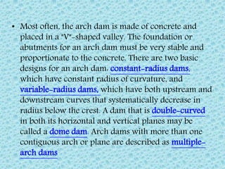
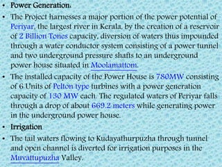
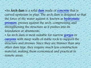
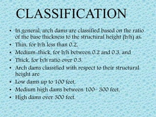
this slide shows different types of dams, their sizes and short information of dams.following dams are explained in this slide which are given below masonry dam, concrete dam, arch dam,earthen dam. this slide also shows types of material required for dam, strength, hight
Reservoir Planning: Introduction; Investigations for reservoir planning; Selection of site for a reservoir; Zones of storage in a reservoir; Storage capacity and yield; Mass inflow curve and demand curve; Calculation of reservoir capacity for a specified yield from the mass inflow curve; Determination of safe yield from a reservoir of a given capacity; Sediment flow in streams; Life of reservoir; Reservoir sediment control; flood routing. Various types of Spillways and design.
DAMS
Types of dams
Selection of dam sites
Geological characters for investigation
Selection of the dam type
Gravity dams
butress dams
embankment dams
arch dams
cupola dams
composite dams
Bhakra Dam
Mir Alam multi-arch dam
Idukki Dam
Tehri Dam
Ujani Dam or bhima dam
DAMS
Types of dams
Selection of dam sites
Geological characters for investigation
Selection of the dam type
Gravity dams
butress dams
embankment dams
arch dams
cupola dams
composite dams
Bhakra Dam
Mir Alam multi-arch dam
Idukki Dam
Tehri Dam
Ujani Dam or bhima dam
Created by Ma. Maiden Continedo from University of Southeastern Philippines taking Bachelor of Science in Secondary Education Major in Biological Science.
The main components of an earth dam are as follows :
1. Impervious core
2. Pervious shell
3. Filter
4. Rock toe
5. U/S slope protection
6. D/S slope protection
7. Cutoff
core shouldnot be less than 3 m and its height should be 1 m more than the maximum water levelin the reservoir.
The upstream pervious zone provides free drainage during sudden drawdown. ,
Usually following types of filters are provided :
(1) Toe filter
(2) Horizontal drainage filter (blanket)
(3) Chimney drains
Such a filter is sometimes known as inverted filter or reverse filter.
Rock toe keeps the phreatic line well within the section and also facilitates drainage.
The following measures are taken to protect the slope.
(1) Rock riprap
(2) Concrete pavement
(3) Steel facing
(4) Bituminous pavement
(5) Precast concrete blocks
Cut off is required to
(1) reduce loss of stored water through foundation and abutments
(2) Prevent sub surface erosion by piping.
Cutoff may be provided in the following ways :
• by providing concrete cutoff wall
• by providing cutoff trench filled with impervious material
• by driving sheet pile
• by curtain grouting
This is a presentation on various hydraulic structures and their uses and cross sections which will help a person to get acquainted with the most important hydraulic structures that are in use in this current world.
It contains detailed information about a Gravity Dam........it also conataims the information in brief & pictures giving a clear view of the Gravity Dams...........It also contains formulas with details of their terms.........
Hydraulic failures .... 40%
Seepage failures…….. 30%
Structural failures .... 30%
(1) Overtopping
(2) Erosion of u/s slope by waves
(3) Erosion of d/s slope by wind and rain
(4) Erosion of d/s toe
(5) Frost action
(1) Overtopping = the design flood is under estimated.
spillway capacity is not adequet
spillway gates are not properly operated
free board is not sufficient
excessive settlement of the foundation and dam
(2) Erosion of u/s slope by waves = The waves developed near the top water surface due to the winds, try to notch out the soil from the upstream face and may even, sometimes, cause the slip of the upstream slope.
Upstream stone pitching or riprap should, therefore, be provided to avoid such failures.
(3) Erosion of d/s slope by wind and rain = The rainwater flowing down the slope; may result in the formation of 'gullies' on the downstream slope thus damaging the dam which may generally lead to partial failure of the dam or in some cases it may cause complete failure of the dam.
Erosion of d/s toe : = Toe erosion may occur due to two reasons :
erosion due to tail water
erosion due to cross currents that may come from spillway buckets.
Frost action : = If the earth dam is located at a place where the temperature falls below the freezing point, frost may form in the pores of the soil in the earth dam.
When there is heaving, the cracks may form in the soil. This may lead to dangerous seepage and consequent failure.
Seepage failures : = Seepage failures may occur due to the following causes :
(1) Piping through the foundation
(2) Piping through the dam
(3) Sloughing of d/s toe
Structural failures :=
Structural failures in earth dams are generally shear failures leading to sliding of the tents or the foundations.
(1) u/s and d/s slope failures due to construction pore pressures
(2) u/s slope failure due to sudden drawdown
(3) D/s slope failure due to steady seepage
(4) Foundation slide due to spontaneous liquefaction
(5) Failure due to earthquake
(6) Failure by spreading
(7) Slope protection failures
(8) Failure due to damage caused by borrowing animals
(9) Failure due to holes caused by leaching of water soluable salts
Criteria for safe Design of Earth Dam :
Section of an Earth Dam :
The design of an earth dam essentially consists of determining such a cross section
the dam which when constructed with the available materials will fulfill its required
tion with adequate safety. Thus there are two aspects of the design of an earth dam.
A dam is a hydraulic structure of fairly impervious material built across a river to create a reservoir on its upstream side for impounding water for various purposes. A detailed ppt on dams,its types,pros and cons.
Using recycled concrete aggregates (RCA) for pavements is crucial to achieving sustainability. Implementing RCA for new pavement can minimize carbon footprint, conserve natural resources, reduce harmful emissions, and lower life cycle costs. Compared to natural aggregate (NA), RCA pavement has fewer comprehensive studies and sustainability assessments.
We have compiled the most important slides from each speaker's presentation. This year’s compilation, available for free, captures the key insights and contributions shared during the DfMAy 2024 conference.
Understanding Inductive Bias in Machine LearningSUTEJAS
This presentation explores the concept of inductive bias in machine learning. It explains how algorithms come with built-in assumptions and preferences that guide the learning process. You'll learn about the different types of inductive bias and how they can impact the performance and generalizability of machine learning models.
The presentation also covers the positive and negative aspects of inductive bias, along with strategies for mitigating potential drawbacks. We'll explore examples of how bias manifests in algorithms like neural networks and decision trees.
By understanding inductive bias, you can gain valuable insights into how machine learning models work and make informed decisions when building and deploying them.
Hybrid optimization of pumped hydro system and solar- Engr. Abdul-Azeez.pdffxintegritypublishin
Advancements in technology unveil a myriad of electrical and electronic breakthroughs geared towards efficiently harnessing limited resources to meet human energy demands. The optimization of hybrid solar PV panels and pumped hydro energy supply systems plays a pivotal role in utilizing natural resources effectively. This initiative not only benefits humanity but also fosters environmental sustainability. The study investigated the design optimization of these hybrid systems, focusing on understanding solar radiation patterns, identifying geographical influences on solar radiation, formulating a mathematical model for system optimization, and determining the optimal configuration of PV panels and pumped hydro storage. Through a comparative analysis approach and eight weeks of data collection, the study addressed key research questions related to solar radiation patterns and optimal system design. The findings highlighted regions with heightened solar radiation levels, showcasing substantial potential for power generation and emphasizing the system's efficiency. Optimizing system design significantly boosted power generation, promoted renewable energy utilization, and enhanced energy storage capacity. The study underscored the benefits of optimizing hybrid solar PV panels and pumped hydro energy supply systems for sustainable energy usage. Optimizing the design of solar PV panels and pumped hydro energy supply systems as examined across diverse climatic conditions in a developing country, not only enhances power generation but also improves the integration of renewable energy sources and boosts energy storage capacities, particularly beneficial for less economically prosperous regions. Additionally, the study provides valuable insights for advancing energy research in economically viable areas. Recommendations included conducting site-specific assessments, utilizing advanced modeling tools, implementing regular maintenance protocols, and enhancing communication among system components.
NUMERICAL SIMULATIONS OF HEAT AND MASS TRANSFER IN CONDENSING HEAT EXCHANGERS...ssuser7dcef0
Power plants release a large amount of water vapor into the
atmosphere through the stack. The flue gas can be a potential
source for obtaining much needed cooling water for a power
plant. If a power plant could recover and reuse a portion of this
moisture, it could reduce its total cooling water intake
requirement. One of the most practical way to recover water
from flue gas is to use a condensing heat exchanger. The power
plant could also recover latent heat due to condensation as well
as sensible heat due to lowering the flue gas exit temperature.
Additionally, harmful acids released from the stack can be
reduced in a condensing heat exchanger by acid condensation. reduced in a condensing heat exchanger by acid condensation.
Condensation of vapors in flue gas is a complicated
phenomenon since heat and mass transfer of water vapor and
various acids simultaneously occur in the presence of noncondensable
gases such as nitrogen and oxygen. Design of a
condenser depends on the knowledge and understanding of the
heat and mass transfer processes. A computer program for
numerical simulations of water (H2O) and sulfuric acid (H2SO4)
condensation in a flue gas condensing heat exchanger was
developed using MATLAB. Governing equations based on
mass and energy balances for the system were derived to
predict variables such as flue gas exit temperature, cooling
water outlet temperature, mole fraction and condensation rates
of water and sulfuric acid vapors. The equations were solved
using an iterative solution technique with calculations of heat
and mass transfer coefficients and physical properties.
Harnessing WebAssembly for Real-time Stateless Streaming PipelinesChristina Lin
Traditionally, dealing with real-time data pipelines has involved significant overhead, even for straightforward tasks like data transformation or masking. However, in this talk, we’ll venture into the dynamic realm of WebAssembly (WASM) and discover how it can revolutionize the creation of stateless streaming pipelines within a Kafka (Redpanda) broker. These pipelines are adept at managing low-latency, high-data-volume scenarios.
Final project report on grocery store management system..pdfKamal Acharya
In today’s fast-changing business environment, it’s extremely important to be able to respond to client needs in the most effective and timely manner. If your customers wish to see your business online and have instant access to your products or services.
Online Grocery Store is an e-commerce website, which retails various grocery products. This project allows viewing various products available enables registered users to purchase desired products instantly using Paytm, UPI payment processor (Instant Pay) and also can place order by using Cash on Delivery (Pay Later) option. This project provides an easy access to Administrators and Managers to view orders placed using Pay Later and Instant Pay options.
In order to develop an e-commerce website, a number of Technologies must be studied and understood. These include multi-tiered architecture, server and client-side scripting techniques, implementation technologies, programming language (such as PHP, HTML, CSS, JavaScript) and MySQL relational databases. This is a project with the objective to develop a basic website where a consumer is provided with a shopping cart website and also to know about the technologies used to develop such a website.
This document will discuss each of the underlying technologies to create and implement an e- commerce website.
Saudi Arabia stands as a titan in the global energy landscape, renowned for its abundant oil and gas resources. It's the largest exporter of petroleum and holds some of the world's most significant reserves. Let's delve into the top 10 oil and gas projects shaping Saudi Arabia's energy future in 2024.
Forklift Classes Overview by Intella PartsIntella Parts
Discover the different forklift classes and their specific applications. Learn how to choose the right forklift for your needs to ensure safety, efficiency, and compliance in your operations.
For more technical information, visit our website https://intellaparts.com
2. •An Arch dam is a solid dam made of concrete that is
curved upstream in plan. The arch dam is designed so that
the force of the water against it, known as hydrostatic
pressure, presses against the arch, compressing and
strengthening the structure as it pushes into its
foundation or abutments.
• An arch dam is most suitable for narrow gorges or
canyons with steep walls of stable rock to support the
structure and stresses. Since they are thinner than any
other dam type, they require much less construction
material, making them economical and practical in
remote areas.
3. • In general, arch dams are classified based on the ratio
of the base thickness to the structural height (b/h) as:
• Thin, for b/h less than 0.2,
• Medium-thick, for b/h between 0.2 and 0.3, and
• Thick, for b/h ratio over 0.3.
• Arch dams classified with respect to their structural
height are
• Low dams up to 100 feet,
• Medium high dams between 100– 300 feet,
• High dams over 300 feet.
CLASSIFICATION
4. The main loads for which an arch dam is designed are
•Dead load
•Hydrostatic load generated by the reservoir and the tail
water
•Temperature load
•Earthquake load
Other miscellaneous loads that affect a dam include: ice
and silt loads, and uplift pressure.[1] [10]
LOADS
5. • Most often, the arch dam is made of concrete and
placed in a "V"-shaped valley. The foundation or
abutments for an arch dam must be very stable and
proportionate to the concrete. There are two basic
designs for an arch dam: constant-radius dams,
which have constant radius of curvature, and
variable-radius dams, which have both upstream and
downstream curves that systematically decrease in
radius below the crest. A dam that is double-curved
in both its horizontal and vertical planes may be
called a dome dam. Arch dams with more than one
contiguous arch or plane are described as multiple-
arch dams
6. The first known arch dam, the Glanum Dam, also
known as the Vallon de Baume Dam, was built by the
Romans in France and it dates back to the 1st century
BC.The dam was about 12m high and 18m in length.
Its radius was about 14m and it consisted of two
masonry walls. The Romans built it to supply nearby
Glanum with water.
The development of arch
dams throughout history
began with the Romans in the
1st century BC and after
several designs and
techniques were developed,
relative uniformity was
achieved in the 20th century.
8. • Location Idukki,Kerala,India
• Purpose: Power Generation, Flood Control
• Type of Dam: Concrete, double curvature parabolic, thin arch.
• Height :168.91 m (554 ft)
• Length :365.85 m (1,200 ft)
• Dam volume: 450,000 m3 (16,000,000 cu ft)
• Spillways: Nil
• Reservoir Total capacity: 1,996×106 m3 (1,618,184 acre·ft)
• Active capacity :1,459×106 m3 (1,182,831 acre·ft)
• Inactive capacity: 536×106 m3 (434,542 acre·ft)
• Catchment Area: 649.3 km2 (251 sq mi)
• Surface area :60 km2 (23 sq mi)
• Normal elevation :732.62 km2 (283 sq mi)
• Installed capacity :780 MW
9. • This dam was constructed along with two
other dams at Cheruthoni and Kulamavu.
Together, the three dams have created an
artificial lake that is 60 km² in area. The
stored water is used to produce electricity
at the Moolamattom Power house, which
is located inside nearby rocky caves. The
Government of Canada aided in the
building of the dam with long term loans
and grants
10. • The idea of constructing a dam for power
generation was first conceived in 1919. As per
history, Shri Kolumban, the head of 'OOrali'
race during 1922, showed the way to the
Malankara Estate Superintendent and his friend
AC Thomas Edattu, who were on hunting spree
in the forest, the spot of present Arch Dam. He
told them of the legend of Kuravan and Kurathi
Hills. Mr. Thomas was impressed by the sight of
water flow between the mountains and it was
his idea that has materialized in the form of
Idukki Arch Dam.
11. • The construction of this Dam commenced on
30 April 1969. Storage of water in Idukki
reservoir commenced in February, 1973. The
inauguration of trial run of the first machine
was celebrated on 4 October 1975.
Commercial operation of the Power Station
was Commissioned on 12 February 1976 by
the then Hon. Prime Minister Smt. Indira
Gandhi
12. • Twice in the past, the shutters had to be opened;
during the northeast monsoon on both occasions.
The first time was in 1981 (when the shutters
were repeatedly opened and shut between
October 29 and November 13) and the second
time was in 1992 (when they were kept open for
12 days from October 12 to 23).
• On both occasions, the water level in the dam
touched the brim only when the storage built up
during the southwest monsoon was augmented
by the inflow received immediately afterwards
following heavy downpour early in the northeast
monsoon
13. • Power Generation:
• The Project harnesses a major portion of the power potential of
Periyar, the largest river in Kerala, by the creation of a reservoir
of 2 Billion Tones capacity, diversion of waters thus impounded
through a water conductor system consisting of a power tunnel
and two underground pressure shafts to an underground
power house situated in Moolamattom.
• The installed capacity of the Power House is 780MW consisting
of 6 Units of Pelton type turbines with a power generation
capacity of 130 MW each. The regulated waters of Periyar falls
through a drop of about 669.2 meters while generating power
in the underground power house.
• Irrigation
• The tail waters flowing to Kudayathurpuzha through tunnel
and open channel is diverted for irrigation purposes in the
Muvattupuzha Valley.