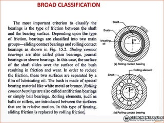
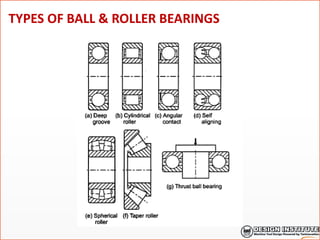
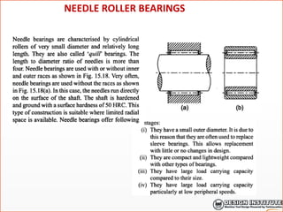
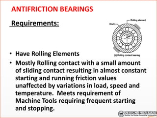
This document discusses anti-friction bearings used in machine tool design. It defines bearings and their purpose of allowing relative motion with minimal friction. It describes the broad classifications and types of ball and roller bearings, including deep groove ball bearings, self-aligning bearings, thrust ball bearings, angular contact ball bearings, cylindrical roller bearings, needle roller bearings, and tapered roller bearings. It discusses bearing requirements, types, dimensions, load capacities, lives, calculations, mounting, lubrication, and failure causes. It also covers spindle bearing arrangements and rigidity calculations.


![ANTIFRICTION BEARINGS
Life of bearing L=[C/P]p or C/P = L1/p
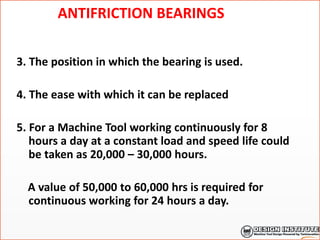
Where,
C = basic dynamic capacity of the bearing in kg,
P = equivalent bearing load in kg,
C/P = loading ratio, p =3 for ball bearings and
p =10/3 for roller bearings,
L = Life in millions of revolutions.](https://image.slidesharecdn.com/antifrictionbearings-240205194025-811aed8c/85/ANTI-FRICTION-BEARINGS-pdf-18-320.jpg)

![ANTIFRICTION BEARINGS
• Thus we can write:
• = 1 + 2 = P [(1/sA) {(a+L)/L}2 + (1/SB) (a/L)2
+ (a2/3E) (L/IL + a/Ia)]
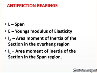
• SA – Radial stiffness of the bearings nearer to
load P
• SB – Radial stiffness of the bearings farther to
load P
• a - overhang](https://image.slidesharecdn.com/antifrictionbearings-240205194025-811aed8c/85/ANTI-FRICTION-BEARINGS-pdf-42-320.jpg)
![ANTIFRICTION BEARINGS
• In the above equation, if the bearings, diameter of
the Spindle and overhang of the Spindle are fixed,
then we note that the stiffness becomes a function
of the bearing span only. The optimum span Lo
based on Static stiffness that provides maximum
stiffness to the system can be derived as
• Lo [6EIL(1/SA+1/SB)+(6EIL/a.SA)Q]1/3
• Where the iterative trial value Q is taken as 4a
initially and the value of Lo is derived.](https://image.slidesharecdn.com/antifrictionbearings-240205194025-811aed8c/85/ANTI-FRICTION-BEARINGS-pdf-44-320.jpg)