BEARING
When there isrelative rotating motion between
two machine parts. One of which supports the
other, the supporting member is called
BEARING. Bearing is very importent element in
any machine.
FUNCTIONS OF BEARING
1. It bears load.
2. It locates rotating part in correct position.
3. It provides free motion to the rotating
part by
reducing friction.
3.
Bearing bears theload in machinery. The term 'load'
refers to the force of weight that is placed on the
bearing. A bearing must be able to support a load placed
on it. Locating the rotating parts in correct position
means hold the rotating part in predetermined place.
Bearings are required to resist motion in one or more
directions while allowing motion to occur in other
directions. Bearings must be able to reduce friction to
provide free motion to a rotating part. Friction is the
resistance to motion that exists between two surfaces
that are in contact with each other. Too much friction can
prevent movement of machine parts, and equipment
may be damaged.
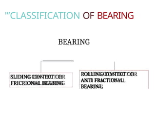
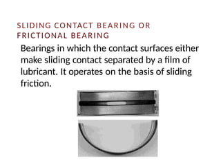
SLIDING CONTACT BEARINGOR
FRICTIONAL BEARING
Bearings in which the contact surfaces either
make sliding contact separated by a film of
lubricant. It operates on the basis of sliding
friction.
6.
Advantages of Slidingcontact bearing:
1. Easy to manufacture,
2. Cost manufacture is low,
3. Quieter in operation particularly
after a
suitable running- in period,
4. It has unlimited life,
5. High load carrying capacity.
6. Less sensitive to injury,
7. Less radial space required,
7.
Disadvantages of SlidingContact Bearing:
1. There required higher starting
torque,
2. Continuous or more lubricant is
needed for lubrication,
3. Loss of lubricant is more,
4. More power is needed for driving,
5. More axial space is required.
8.
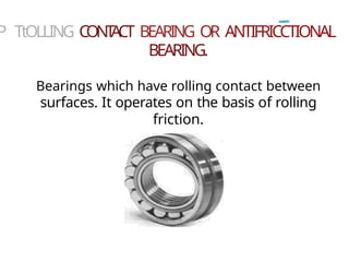
P TtOLLING CONT
ACTBEARING OR ANTIFRICCTIONAL
BEARING.
Bearings which have rolling contact between
surfaces. It operates on the basis of rolling
friction.
9.
Advantages of R.C.bearings:
1. Lower axial space required,
2. Operates on minimum friction,
3. Lower Power consumption,
4. Low starting torque,
5. Less lubricant is needed for
lubrications,
6. Easy maintenance,
7. More axial rigidity in this case.
10.
Disadvantages of R.C.bearings:
1) Manufacturing Process is complex in
nature,
2) Cost of manufacturing is higher,
3) It has limited life in term s of
millions
of revolutions,
4) More sensitive to foreign bodies &
11.
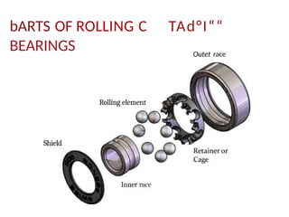
bARTS OF ROLLINGC
BEARINGS
TAd°I““
Outet race
Shield
Rolling element
Inner race
12.
Rolling contact Bearingconsists of
the following main parts.
1. Outer ring OR outer race.
2. Inner ring OR Inner race
3. Retainer or Cage
4. Rolling elements.
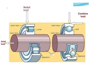
13.
Bearings can beclassified according to
type of load carried by the bearing.
1. Bearings for radial load (Radial bearings).
2. Bearings for axial load (Thrust bearings).
3. Bearings for combined load (It takes both
radial and axial load).
BEARINGS FOR RADIALLOAD
Different types of R. C. bearings which can be
used for radial loads are,
1. Single or double row deep groove ball
bearings.
2. Double row self-aligning ball bearing.
3. Cylindrical roller bearings.
4. Single or double row self-aligning ball
bearings.
16.
BEARINGS FOR COMBINEDLOAD
The following bearings are suitable when loads are
made up of one component perpendicular to the
axis of the rotation and other parallel to the axis of
rotation.
1. Angular contact ball bearings either of the
single row type (to be fitted in opposite pairs) or
of the double row type.
2. Spherical roller thrust bearings.
3. Taper roller bearings single or paired (for axial
load in either one or both directions
respectively.)
17.
BEARINGS FOR THRUSTLOAD
Different types of R. C. bearings which can
be used for thrust loads are :
1. Single or double thrust ball bearings
(for thrust load in either one or
both direction5 respectively).
Cylindrical roller thrust bearings
18.
Bearings can bec/assif/er/ accordfr›p
fo
fype of rolling e/ement used. They are:
•BalI Bearing.
•RolIer Bearing
Difference between Ball and Roller
bearings.
1. Can carry lighter load. 1. Can generally
carry heavier load.
2. Can run at higher speed. 2. Can run at
lower speed
3. Maximum friction that may occur is
0.0015.
19.
BA L LBEARINGS
•SingIe row deep groove ball bearings.
This is the most common type of ball bearings in
general engineering. This type has the following
advantages.
1. It can withstand considerable amount of thrust load
in
addition to radial load
2. It can function successfully at very high speed.
3. As there is no flexibility is provided in this type,
alignment of the shaft and housing should be as
correct as possible. Bearings of this type are available
with side shields, seals and snap rings.
20.
—. _ _-. z -
.
*
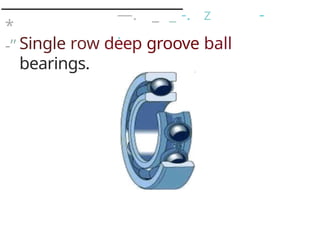
-” Single row deep groove ball
bearings.
21.
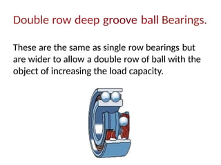
Double row deepgroove ball Bearings.
These are the same as single row bearings but
are wider to allow a double row of ball with the
object of increasing the load capacity.
22.
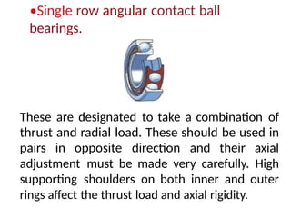
•SingIe row angularcontact ball
bearings.
These are designated to take a combination of
thrust and radial load. These should be used in
pairs in opposite direction and their axial
adjustment must be made very carefully. High
supporting shoulders on both inner and outer
rings affect the thrust load and axial rigidity.
23.
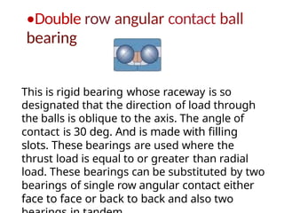
•DoubIe row angularcontact ball
bearing
This is rigid bearing whose raceway is so
designated that the direction of load through
the balls is oblique to the axis. The angle of
contact is 30 deg. And is made with filling
slots. These bearings are used where the
thrust load is equal to or greater than radial
load. These bearings can be substituted by two
bearings of single row angular contact either
face to face or back to back and also two
24.
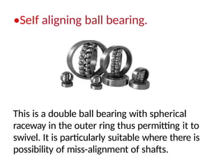
•SeIf aligning ballbearing.
This is a double ball bearing with spherical
raceway in the outer ring thus permitting it to
swivel. It is particularly suitable where there is
possibility of miss-alignment of shafts.
25.
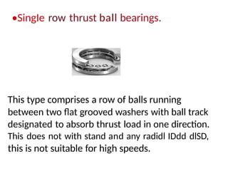
•SingIe row thrustball bearings.
This type comprises a row of balls running
between two flat grooved washers with ball track
designated to absorb thrust load in one direction.
This does not with stand and any radidl IDdd dlSD,
this is not suitable for high speeds.
26.
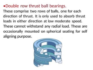
•Double row thrustball bearings.
These comprise two rows of balls, one for each
direction of thrust. It is only used to absorb thrust
loads in either direction at low moderate speed.
These cannot withstand any radial load. These are
occasionally mounted on spherical seating for self
aligning purpose.
27.
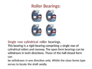
Roller Bearings:
Single rowcylindrical roller bearings.
This bearing is a rigid bearing comprising a single row of
cylindrical rollers and raceway. The open form bearings can be
withdrawn in both directions. Those of the half-closed form
can
be withdrawn in one direction only. Whilst the close forms type
serves to locate the shaft axially.
28.
Double row cylindricalroller bearings.
These are twice as wide as the single row type.
These are also called Duplex bearings and can
sustain extremely heavy loads. These are a
available in either separable in either separable
inner or outer races.
29.
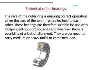
Spherical roller bearings.
Therace of the outer ring is ensuring correct operation
when the axes of the two rings are inclined to each
other. These bearings are therefore suitable for use with
independent support housings and wherever there is
possibility of a lack of alignment. They are designed to
carry medium or heavy radial or combined load.
30.
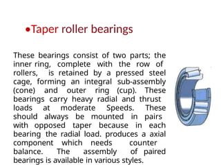
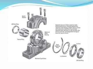
•Taper roller bearings
Thesebearings consist of two parts; the
inner ring, complete with the row of
rollers, is retained by a pressed steel
cage, forming an integral sub-assembly
(cone) and outer ring (cup). These
bearings carry heavy radial and thrust
loads at moderate Speeds. These
should always be mounted in pairs
with opposed taper because in each
bearing the radial load. produces a axial
component which needs counter
balance. The assembly of paired
bearings is available in various styles.
31.
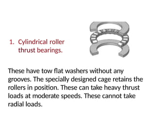
1. Cylindrical roller
thrustbearings.
These have tow flat washers without any
grooves. The specially designed cage retains the
rollers in position. These can take heavy thrust
loads at moderate speeds. These cannot take
radial loads.
32.
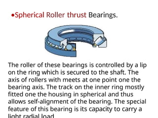
•Spherical Roller thrustBearings.
The roller of these bearings is controlled by a lip
on the ring which is secured to the shaft. The
axis of rollers with meets at one point one the
bearing axis. The track on the inner ring mostly
fitted one the housing in spherical and thus
allows self-alignment of the bearing. The special
feature of this bearing is its capacity to carry a
33.
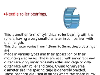
•NeedIe roller bearings.
Thisis another form of cylindrical roller bearing with the
rollers, having a very small diameter in comparison with
their length.
This diameter varies from 1.5mm to Smm. these bearings
are
made in various types and their application or their
mounting also varies. These are used with inner race and
outer race, only inner race with roller and cage or only
outer race with roller and cage. Owing to very small
diameter size the spacing cage is generally omitted.
34.
BEARING COMPONENTS ANDMATERIALS
1. The rings and rolling elements of rolling
bearings are generally made form
through hardened high grade carbon
chromium steel having a high degree of
cleanliness. Or special applications case
hardened or even stainless steel may be
used.
2. Each individual bearing receives optimum
heat treatment, resulting in hardness normally
between 59 and 65 HRC. Pressed steel, or
brass cages are normally used for small and
35.
3
:
- Injection moldedplastic cages are,
however, used more and more as Standard
or small and medium size bearings.
4. Large bearings generally have
machined cages which are usually made of
brass, but even steel; spherical graphite cast
iron and light alloys are used for machined
cages.
Shields are made of steel sheet only and
form a narrow gap with the inner ring. Seals
protect bearings better than shields do, but
the heat resulting from the friction between
seal lip and the inner ring will Reduce the
36.
INTERNAL CLEARANCE
The bearinginternal clearance is defined as the total
distance through with one bearing ring can be made
relative to the other under zero measuring loads.
1. Movement in the radial direction called radial internal
clearance;
2. Movement in the Axial direction called Axial internal
clearance;
The internal clearance will vary from bearing type to
bearing type. The most common clearance is
NORMAL (with no suffix). Internal clearance smaller
than normal are designated by suffixes C1 and C2
while internal clearances larger than normal are
designated by C3, C4 and C5.
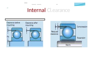
Reasons for providinginternal clearance:
1.In order to fit a bearing tightly on a shaft, it is
necessary that the shaft is slightly Larger than the bore
of inner ring. When the bearing is mounted, the inner
ring will expand and consequently the space available for
the rolling elements will be reduced. (Sometimes the
housing seating's are made slightly smaller than the
outside diameter of the outer ring resulting in
compression of the outer ring and hence further
reduction of available space for rolling elements.)
The reduction in space available for rolling elements
when the bearing mounted is accommodated by the
internal clearance.
2. Steel will expand with increased temperature. In
Dperation
the temperature of the various parts of a bearing will
39.
LUORTCATION OF BEAItINGS
Thepurpose of lubrication
is.
1. To reduce friction between the rolling
members.
2. To protect bearing from corrosion.
3. To prevent the intrusion of drift into the
bearing.
4. To reduce the running noise.
5. To dissipate heat.
40.
1. Before beingpacked,- the bearings
are costed with preservative
grease which prevent corrosion.
Bearings,therefore, should be left in
their original packing until just before
they are fitted.
2. Never wasn out bearings which are available
in
the suppliers packing.
3. If due to any reason the bearings
become dirty, they
should be cleaned in fresh petrol and re
lubricated immediately.
4. Avoid using compressed air for
cleaning bearings as
41.
E
Oil Lubrication iscon ned to certain ca
s:
1-. Bearing running at very high temperatures. Oil
should be fed through them continuously for
cooling purposes. (The oil should be sucked
through the bearing and never forced thfOU9h.)
2.Bearings fitted on the vertical shafts where it is
difficult to seal in the grease, so that drip-lubrication with
oil is preferable.
3.Bearing installed in machines which are
already lubricated with oil and in which it is
difficult to separate the lubrication of
bearings that of the other components of the
machine.
4. Self-aligning thrust roller bearings which are
almost
43.
ROLLING BEARING—DAMAGE ANDITS CAUSED
The life of ball or roller bearing depends upon the
total number of stress cycles and loads incurred by
rolling elements and raceways.
Normal fatigue manifests itself by flaking or
Spalling of the rolling surfaces. If the bearing
continues in service an increased localized stress may
result in catastrophic ring fracture.
If the bearing fails earlier than predicted by the
fatigue life, it should be checked for overloading.
With this failure cause excluded,
thought should be given to the possibility of poor
installation or maintenance or to operational wear.
44.
Why does abearing fail?
An usual pattei'n of the running track suggest intei'na1 nipping
which may be caused by exceedingly tight fits, excessive
axial adjustment, malformation of the bearing seats of
the shaft or the housing, misalignment, or when the axial
freedom of the floating bearing is lost.
Localized damage to the i'aceway such as nicks, score
marks, or indentations suggest faulty mounting.
This type of damage occurs if, for instance, the inner ring of a
cylindrical roller bearing is pushed into the outer ring in a tilted
position or if the mounting pressure is transmitted thi'ough the
rolling elements.
45.
Fat Its iiiDesign
Rolling bearing ring should be fully supported on the
shaft and in the housing. A groove in the seating
area will cause localizedstress
concentrations and subsequent raceway destruction.
Similar damage occurs when a set screw is used to
clamp the ring or when grooves or bores are ground
into the bearing after its completion in manufacture.
Corrosion is caused by inadequate sealing against
moisture, Acid fumes, lubricant containing acids,
condensation, unsuitable storage.
46.
Ei4tl’alice of Dirt
Entrance of dirt may be
due to uncleanparts,
sand in housing
(castings), inadequate seals,
contaminated lubricants, Metallic
abrasion from gears
brought into the bearing by the lubricant.
Bi inelling
Brinelling is caused by static overloading, shock
and vibration on stationary bearing (e.g. during
transportation), passage of electric current
through the bearing.