Download to read offline

![Signal & Image Processing : An International Journal (SIPIJ) Vol.5, No.6, December 2014
57
intensity-based algorithms through novel modifications to the algorithm and by the way of analog
signal processing.
2.1. Normalized Cross Correlation (NCC)
2.1.1. Review of Related Work
There has been a lot of research done on stereo image registration techniques as it relates to
multiple fields like computer vision, medical imaging, photography etc. A variety of algorithms,
both feature based and intensity based have been developed. In [1], the author provides a survey
of different image registration techniques used in various fields.
In this study we are mainly concerned with the implementation of an intensity based image
alignment algorithm in hardware. There has been some work done in this regard but most of them
are improvements to the old algorithms and some are digital hardware implementations of these
algorithms.
In [2] Lewis proposes a fast normalized cross correlation algorithm, which reduces the
computational complexity of the normalized cross correlation algorithm through the use of sum
table methods to pre-compute the normalizing denominator coefficients. In [3] the authors take
the fast normalized cross correlation algorithm one step further by using rectangular basis
functions to approximate the template image. The number of computations in the numerator will
then be directly proportional to the number of basis functions used to represent the template
image. Using a smaller number of basis functions to represent the template image will certainly
reduce the computation but it may give a bad approximation of the template image, which would
result in poor image alignment. In [4] the author uses a pipelined FPGA architecture to perform
the Normalized Cross Correlation operation. This increases the computation speed significantly.
There have been various other improvements and implementations of the NCC algorithm in
literature however none of the implementations, to our knowledge, try to tackle the computational
intensity problem of the normalized cross correlation algorithm from an analog signal processing
perspective.
2.1.2 Reasons for Choosing Normalized Cross Correlation
There are a lot of intensity based stereo correspondence algorithms. We chose Normalized Cross
Correlation (NCC) as the algorithm that we would implement because of the following reasons:
1. The images being aligned in the patch based approach have translation in the X and Y
direction but no rotation or shear. NCC algorithm performs well for such images.
2. NCC is less sensitive to variation in the intensity values of two images being aligned.
3. The NCC algorithm is computationally intensive. Hence it would be challenging to come
up with methods to reduce the computation and make it implementable in real time or
near real time and we believe analog signal processing would have a lot of value in such
situations.
2.1.3 The General Algorithm
Template matching is one of the simplest methods used for image alignment. There are two
images to be aligned. One image is called the template and the other image is called the reference.
The template image is generally divided into blocks of smaller images. There is always a tradeoff
between the depth accuracy that can be achieved and computation that can be handled in a NCC
algorithm. Increasing the number of blocks by reducing the block size increases the accuracy to](https://image.slidesharecdn.com/analogsignalprocessingapproachforcoarseandfinedepthestimation-150102222112-conversion-gate01/85/Analog-signal-processing-approach-for-coarse-and-fine-depth-estimation-3-320.jpg)
![Signal & Image Processing : An International Journal (SIPIJ) Vol.5, No.6, December 2014
58
which depth can be estimated but it also increases the number of times the computations have to
be performed. There is also a limit to which the block size can be reduced. If the block size is
made too small then it might not have enough information to align with a matching block.
Therefore choosing an optimum template block size is important.
Each template block is shifted on top of the reference image and at each point a correlation
coefficient is calculated. This correlation coefficient will act as a similarity metric to identify the
closest matching blocks.
The disadvantage of using cross correlation as a similarity measure is that it is an absolute value.
Its value depends on the size of the template block. Also the cross correlation value of two exactly
matching blocks may be less than the cross correlation value of a template block and a bright
spot. The way around this problem is to normalize the cross correlation equation.
Equation (1) shows how the NCC algorithm is implemented [2].
(1)
In the above equation represents the mean of the template image block and is the mean
value of the reference image present under the template image block. The two summation terms
in the denominator of the above equation represent the variances of the zero-mean reference
image and template image respectively. Due to this normalization, the correlation coefficient is
independent of changes to image brightness and contrast.
The denominator of the NCC equation can be calculated efficiently through the use of sum tables
as suggested in [2]. However the numerator of the NCC is still computationally intensive. A
direct implementation of the numerator of NCC algorithm on a template image of size (Tx x Ty)
and a reference image of size (Rx x Ry) would require (Tx*Ty) multiplications and additions for
each shift (u,v). Reducing the template image size would reduce the number of computations per
block but it will also increase the total number of blocks on which the NCC has to be performed.
2.2. Modification to the NCC Algorithm
In a general normalized cross correlation algorithm the template image is divided into blocks and
each block is shifted on top of the reference image. At each shift a normalized correlation
coefficient is calculated. All the pixels in the block are used to perform this calculation as shown
in equation (1). Once this is done for all shifts, a best matching block is picked and all the pixels
in the template block are assigned the same shift/disparity value.
In the worst case scenario where there is no information available about the camera system or the
scene, a brute force approach has to be used where the template image blocks have to be shifted
all over the reference image. The computational complexity in this case would be very high.
When some information is available about the camera system the maximum disparity that will be
observed can be calculated and hence the number of shifts can be restricted. However this does
not address the fact that the number of computations that have to be performed per block for each
shift is still high.
A pre-processing step that is generally used in most stereo correspondence algorithms is image
rectification. Image rectification projects stereo images onto a common reference plane so that the](https://image.slidesharecdn.com/analogsignalprocessingapproachforcoarseandfinedepthestimation-150102222112-conversion-gate01/85/Analog-signal-processing-approach-for-coarse-and-fine-depth-estimation-4-320.jpg)
![Signal & Image Processing : An International Journal (SIPIJ) Vol.5, No.6, December 2014
66
analog summer, multiplier and integrator. We have performed initial circuit simulations for these
components. Table 1 shown below gives approximate values of the power consumption for these
components calculated for a dynamic range of 40dB based on these simulations. Here we assume
that we have 64 analog channels in the architecture shown in Figure 2 and the number of
components required are calculated based on that. The actual power consumptions can only be
obtained once the components are realized and integrated.
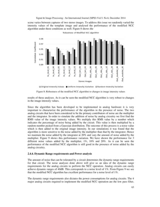
Figure 9: Performance of the modified NCC algorithm in the presence of Noise
Table 1: Approximate power consumption values for the analog circuits
Component Quantity Power Consumption
LPF 64 2.8mW/LPF*64 = 179.2mW
Summer 64 0.549mW/sum*64=35.13mW
Multiplier 32 1.83µW/mul*32 = 0.058mW
Integrators 32 0.024mW/int*32 = 0.768mW
The total power consumption by the analog circuitry is 215.15mW. Based on some of the digital
implementations such as [11] and [12], we see that the power consumption for an analog
implementation will be very low compared to that of a digital implementation. This shows that
we have significant power savings as well.
2.4.5. A Note on Computation Time
The modifications proposed to the NCC algorithm contribute to a significant reduction in the
computation of the algorithm. Simulation results show a 50% reduction in computation time for
the modified NCC algorithm over the original algorithm. The other factors which add to the
reduction of computation time are the novel imaging architecture and analog processing. In the
new imaging architecture the analog processor works in parallel with the digital acquisition
system and hence it does not have to wait for the entire image to be acquired before the
processing starts. By the time the acquisition is done the analog processor would have finished its
computation. So the image acquisition time can also be added towards the reduction in
computation time. The implementation of the NCC algorithm is being done in analog hardware.
The analog processor is not limited by the data converters (ADCs) or logic delays. The settling](https://image.slidesharecdn.com/analogsignalprocessingapproachforcoarseandfinedepthestimation-150102222112-conversion-gate01/85/Analog-signal-processing-approach-for-coarse-and-fine-depth-estimation-12-320.jpg)
![Signal & Image Processing : An International Journal (SIPIJ) Vol.5, No.6, December 2014
67
times of well-designed analog circuits are very small. Hence an analog implementation of the
NCC algorithm would be faster than a digital implementation and would contribute towards a
further reduction in computation time.
3. PER-PIXEL STEREO CORRESPONDENCE ALGORITHM
The patch based stereo correspondence algorithm discussed in the previous section produces very
coarse depth maps. This approach is suitable for applications where speed is more important than
accuracy. However in some of the other applications, a more accurate or a finer depth map is
required. In these cases, a per-pixel approach of finding depth is preferred to a patch based
approach. In this section we discuss a per-pixel stereo correspondence algorithm. The similarity
measure used here is Sum Absolute Difference (SAD). We show that using a slightly lesser
overlap between blocks can give a similar performance while significantly reducing the
computational load. A hardware architecture is proposed which can further speed up computation.
3.1. Review of Related Work
There are some major challenges associated with recovering an accurate depth map like the
presence of occluded pixels, noise in images and depth discontinuities. A multitude of stereo
correspondence algorithms have been developed which address some or all of these challenges. In
[14] the authors provide a thorough analysis and overview of the different stereo correspondence
algorithms. Klaus et al. [15] use a segment-based stereo correspondence algorithm which uses
belief propagation and a self-adapting dissimilarity measure.
3.2. Disparity Estimation Using Overlapping Blocks
Most of these per-pixel stereo correspondence algorithms calculate a coarse depth estimate of the
scene using local window based approaches as the first step. One of the major problems
associated with using the patch based approach for calculating the coarse depth estimates is that
the algorithm does not perform well when there are depth discontinuities in a block. Also
depending on the application the estimated depth may be too coarse.
In order to obtain a finer depth estimate and reduce the effect of depth discontinuities overlapping
blocks can be used. The higher the overlap, lesser is the effect of depth discontinuities and a finer
depth map is produced. If the blocks are completely overlapping (except for one pixel) then this
method can be thought of as per-pixel depth estimation. The drawback of using such an approach
is that computation increases with the amount of overlap. The computational intensity of such an
algorithm is orders of magnitude higher than the patch based approach and the digital system will
be bogged down by the high computational load. In order to get around this problem we can use
analog signal processing and a hybrid architecture very similar to the one shown in Figure 1, the
change being the similarity measure used.
The similarity measure being used here is Sum Absolute Differences (SAD) as shown in the
equation below.
(2)
In equation (2), R is the reference image block and T is the template image block. The parallel
analog correlator in the architecture of Figure 1 will be replaced by an analog processor that can
perform the above SAD operation.](https://image.slidesharecdn.com/analogsignalprocessingapproachforcoarseandfinedepthestimation-150102222112-conversion-gate01/85/Analog-signal-processing-approach-for-coarse-and-fine-depth-estimation-13-320.jpg)
![Signal & Image Processing : An International Journal (SIPIJ) Vol.5, No.6, December 2014
68
Most of the stereo correspondence algorithms in the digital domain operate on rectified images. In
the new architecture we have access to raw analog data directly from the sensor and not the
rectified images. Hence in this implementation we check for disparity in both the x and y
directions.
3.3. Hardware Architecture
Figure 10 below shows the implementation of the SAD algorithm in the new hardware
architecture. As before we have N analog channels of which the odd numbered channels are
reading the reference image data and the even numbered channels are reading the template image
data. In order to have a faster computation the entire rows or columns of the reference and
template image data are read at once and their difference is calculated. This data is then passed
through an absolute value circuit and then through the integrator. The output of the integrator is
sampled at a particular rate depending on the size of the window/block. The integrator
accomplishes a 1D summation. These values are then fed into a DSP where the second
dimensional summation is performed along with any further processing and decision making that
is required. As before the image acquisition is independent of processing and they are happening
in parallel. This leads to a significant reduction in computation time.
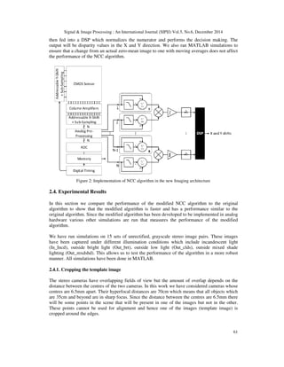
CMOS Sensor
AddressableY-Shift
+Sub-Sampling
Column Amplifiers
Digital Timing
ADC
Addressable X-Shift
+ Sub-Sampling
Memory
DSP
N
N-1
1
2
X and Y shifts
ʃ∑
R
-
ʃ
R
N
N
Analog Pre-
Processing
ABS
∑ ABS
-
Figure 10: Implementation of the SAD algorithm in the new imaging architecture
Another feature that can obtained from this new architecture is the varying overlap of blocks. The
amount of overlap determines the accuracy to which the depth or disparity can be obtained.
3.4. Experimental Results
In this section we test the performance of the SAD algorithm by performing various simulations
in Matlab. Since the SAD algorithm will be implemented in analog hardware we have considered
the performance of the algorithm in the presence of added noise by the analog circuitry. We have
run simulations on two stereo images from the standard Middlebury dataset [16].](https://image.slidesharecdn.com/analogsignalprocessingapproachforcoarseandfinedepthestimation-150102222112-conversion-gate01/85/Analog-signal-processing-approach-for-coarse-and-fine-depth-estimation-14-320.jpg)
![Signal & Image Processing : An International Journal (SIPIJ) Vol.5, No.6, December 2014
69
The performance of the image alignment algorithms can be evaluated in a variety of different
ways. Here the performance measures used are correlation coefficient and RMS disparity error.
Once the final disparity values for all the template blocks or pixels are obtained, each template
block or pixel is shifted by the disparity values obtained. At the end of this process the two stereo
images have been aligned. The correlation coefficient is calculated between the two aligned
images and it is used as an indicator of the performance of the algorithm. The Middlebury dataset
also has a ground truth disparity map available. This is used to compute the RMS disparity error
between the ground truth disparity map and the computed disparity map which can also be used
as a performance measure as suggested in [14].
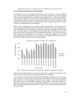
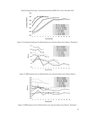
Figures 11 and 12 shows the correlation coefficients obtained for the Middlebury dataset ‘Baby1’
and ‘Bowling1’ respectively. We have measured the correlation coefficient for 4 different block
sizes 5x5, 7x7, 11x11 and 15x15 pixels. The overlap between the blocks is varied for each block
size, from 0 pixels which represents a patch based approach to n-1 pixels which represents the
per-pixel approach, where n is the size of the block. The x-axis in figures 11 and 12 represents the
pixel overlaps. For each block size and overlap we compare the performance of the SAD
algorithm with and without noise being added by the analog circuitry. The amount of noise added
by the analog circuits is fixed at 5% of the RMS signal level. The procedure for adding noise is
the same as explained in section 2.4.3. As can be seen from the figures the performance of the
algorithm is good even in the presence of noise.
Figures 13 and 14 shows the comparison of the RMS disparity error between the ground truth
disparity map and the computed disparity map for the Middlebury dataset ‘Baby1’ and
‘Bowling1’ respectively for 4 different block sizes. The overlap between blocks is also varied as
before which is represented by the x-axis of figures 13 and 14. We compare the performance of
the SAD algorithm both with and without the noise added by the analog circuitry. The amount of
noise added is 5% of the RMS signal level. As can be seen from the figures the performance of
the algorithm after the addition of noise is very close to the ideal case.
Figure 11: Correlation Coefficient for different block sizes with and without noise (Dataset: ‘Baby1’)](https://image.slidesharecdn.com/analogsignalprocessingapproachforcoarseandfinedepthestimation-150102222112-conversion-gate01/85/Analog-signal-processing-approach-for-coarse-and-fine-depth-estimation-15-320.jpg)
![Signal & Image Processing : An International Journal (SIPIJ) Vol.5, No.6, December 2014
71
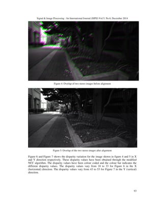
Figures 15 shows the overlap of two stereo image pairs before alignment (left image) and after
alignment (right image). Before alignment the correlation coefficient is 0.5189 and after
alignment the correlation coefficient is 0.9906.
Figure 15: Overlap of stereo images before alignment (left) and after alignment (right)
(Dataset: ‘Bowling1’)
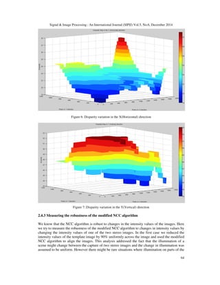
Figure 16 shows the x disparity map obtained for the ‘Bowling1’ dataset for a window size of 5x5
pixels for different overlaps. The first row has 3 disparity maps with 0, 1 and 2 pixel overlap
between blocks. The second row has 2 disparity maps with 3 and 4 pixel overlap between blocks.
The disparity map has been generated after considering a 5% noise added by the analog circuitry
during processing. As can be seen from the disparity map, as the overlap increases the disparity
map generated gets finer but it hits a saturation level at a certain point after which we do not see a
lot of improvement. This is also evident from the correlation coefficient curves in figures 11 and
12. This shows that we have to select an overlap factor which gives a good performance while not
introducing unnecessary computation. We believe an overlap factor of 60% to 70% would be a
good trade-off between computation and accuracy of the disparity map. By reducing the overlap
the amount of computation is also reduced significantly. Due to this modification an average
speed up of 4x was observed in Matlab run time.
Figure 16: X disparity map for with different overlaps for a window size of 5x5 pixels (Dataset: Bowlign1)
The figure below shows the disparity map in the y direction for the ‘Bowling1’ dataset for a
window size of 5x5 pixels and 3 different overlap settings of 2, 3 and 4 pixels. The images in the
Middlebury dataset are rectified but figure 17 shows that there are some variations in the y
direction which were not accounted for in the rectification process. This may be due to pixel
occlusions [17]. The advantage of performing a coarse alignment in the analog domain is that the
operation is being performed on raw image data i.e. unrectified images. Hence we calculate
disparities in both x and y directions. This gives us extra information about the pixel disparities
which cannot be obtained by performing stereo correspondence on rectified stereo images.](https://image.slidesharecdn.com/analogsignalprocessingapproachforcoarseandfinedepthestimation-150102222112-conversion-gate01/85/Analog-signal-processing-approach-for-coarse-and-fine-depth-estimation-17-320.jpg)
![Signal & Image Processing : An International Journal (SIPIJ) Vol.5, No.6, December 2014
72
Figure 17: Y disparity map for with different overlaps for a window size of 5x5 pixels
(Dataset: ‘Bowling1’)
4. CONCLUSIONS
In this work we propose analog signal processing as a solution for handling the high
computational load of some of the image processing algorithms while simultaneously meeting the
reduced SWaP requirements. The analog processor will be used to augment the digital processor
and work in parallel with it to perform key computations, making the system faster and more
efficient. We implement two highly computational stereo correspondence algorithms to align
stereo image pairs. Novel modifications were proposed to both the NCC algorithm and SAD
algorithm which reduced the computation and made the algorithm efficiently implementable in
analog hardware. The modified NCC algorithm has a 50% reduction in Matlab computation time
over the original algorithm and the modified SAD algorithm has a speed up of more than 4x in
Matlab computation time over the original algorithm. An approximate power consumption of
215.15mW was obtained for the analog correlation block. The SAD algorithm produced a finer
depth map. The actual analog hardware implementation of the algorithm and the new imaging
architecture will contribute to a further reduction in computation time as compared to a digital
implementation. Various other simulations were also run to check the robustness and performance
of the algorithm. The experimental results obtained are very promising and we believe analog
processing will be a viable solution to these problems. As a part of the future work and as a proof-
of-concept the analog image correlator circuit will be built from commercially available off the
shelf components. A test plan will be setup for this circuit. Once the required results are obtained,
the next step will be to build the architecture in silicon.
REFERENCES
[1] Brown, L, (1992) “A survey of image registration techniques”, ACM Journal (CSUR), Vol. 24, Issue
4, pp325-376.
[2] Lewis, J.P, (1995) “Fast Normalized Cross Correlation”, Industrial Light & Magic.
[3] Briechle, Kai, & Uwe D. Hanebeck, (2001) "Template matching using fast normalized cross
correlation", Aerospace/Defense Sensing, Simulation, and Controls. International Society for Optics
and Photonics.
[4] Radhamani & R, Keshaveni, (2012) “FPGA implementation of efficient and High speed template
matching module”, IJRTE, Vol. 2, Issue- 2.
[5] Khaleghi, B et al. (2008) “A new Miniaturized Embedded Stereo-Vision System (MESVS-I)”, CRV,
pp26-33.
[6] Gupta, N, (2007) “A VLSI architecture for Image Registration in Real Time”, IEEE Transactions on
VLSI systems, Vol. 15, Issue 9, pp981-989.
[7] Roma, N et al. (2002) “A comparative analysis of cross-correlation matching algorithms using a
pyramidal resolution approach”, INESC Portugal.
[8] Adhikari, G. et al. (2012) “Fast normalized cross correlation with early elimination condition”, IEEE
Transaction, ICRTIT 2012, pp136-140.
[9] Tsai, Du-Ming & Chien-Ta Lin, (2003) “Fast normalized cross correlation for defect detection”,
Pattern Recognition Letters 24.15, pp2625-2631.
[10] Szeliski, R, (2004) “Image Alignment and Stitching: A tutorial”, Technical Report, Microsoft
Research, Microsoft Corporation, MSR-TR-2004-92.](https://image.slidesharecdn.com/analogsignalprocessingapproachforcoarseandfinedepthestimation-150102222112-conversion-gate01/85/Analog-signal-processing-approach-for-coarse-and-fine-depth-estimation-18-320.jpg)
![Signal & Image Processing : An International Journal (SIPIJ) Vol.5, No.6, December 2014
73
[11] Ttofis, C., & Theocharides, T. (2012) “Towards accurate hardware stereo correspondence: A real-
time FPGA implementation of a segmentation-based adaptive support weight algorithm”, In
Proceedings of the Conference on Design, Automation and Test in Europe, pp703-708.
[12] Xiaotao Wang & Xingbo Wang, (2009) "FPGA Based Parallel Architectures for Normalized Cross-
Correlation”, 1st International Conference Information Science and Engineering (ICISE), pp225-229.
[13] San Yong, Y., & Hon, H. W. (2008) “Disparity estimation for objects of interest”, World Academy of
Science, Engineering and Technology, 43.
[14] Scharstein, D. & Szeliski, R. (2002) “A taxonomy and evaluation of dense two-frame stereo
correspondence algorithms”. International Journal of Computer Vision, pp7-42.
[15] Klaus, A., Sormann, M. & Karner, K. (2006) “Segment-Based Stereo Matching Using Belief
Propagation and a Self-Adapting Dissimilarity Measure”, ICPR
[16] Hirschmüller, H. & Scharstein, D., (2007) “Evaluation of cost functions for stereo matching”, IEEE
Computer Society Conference on Computer Vision and Pattern Recognition (CVPR).
[17] Rzeszutek, R., Dong Tian & Vetro, A. (2013) “Disparity estimation of misaligned images in a
scanline optimization framework”, ICASSP.
AUTHORS
Nihar Athreyas received his B.E. degree in Electronics and Communication
Engineering from VTU Belgaum, India and M.S. degree in Electrical and Computer
Engineering from University of Massachusetts, Amherst, MA, in 2010 and 2013
respectively. He is currently pursuing his doctoral degree under the supervision of Dr.
Dev Gupta at University of Massachusetts, Amherst, MA. He joined Newlans, Inc.,
Acton, MA in June of 2014 as an Intern. His current research interests include
communications, CMOS analog design and applications of analog signal processing.
Zhiguo Lai received the B.S. degree in mechanical engineering from Tsinghua
University, Beijing, China, the M.S. degree in electrical and computer engineering
from University of Alaska, Fairbanks, AK, and the Ph.D. degree in electrical
engineering from University of Massachusetts, Amherst, MA, in 1999, 2002, and
2007, respectively. From summer of 2007 to summer of 2009, he was a postdoctoral
fellow at University of Massachusetts, Amherst, MA, working on narrowband
interference mitigation for UWB systems. Since 2009, he has been with Newlans, Inc.,
Acton, MA. His research interests include design of programmable CMOS filters,
wideband analog signal processing, and quantum computation. He is currently working on analog
computation using deep-submicron CMOS technology.
Dev V. Gupta received his Ph.D. in 1977 from the University of Massachusetts,
Amherst. He held various engineering positions at the Bell Laboratories in Andover,
MA, from 1977 to 1985. He was the General Manager at Integrated Network
Corporation, a manufacturer of DSL access products, from 1985 to 1995. Dr. Gupta
founded two companies, Dagaz Technologies and Maxcomm, which were acquired by
Cisco Systems in 1997 and 1999 respectively. These companies developed and
manufactured telephone exchange and voice and data equipment for DSL. He was
Cisco’s VP of Architecture in the access business unit between founding Dagaz
Technologies and Maxcomm. In 2000, he founded Narad Networks which
manufactured Gigabit Ethernet networking equipment for the cable industry. Narad Networks (renamed
PhyFlex) was acquired by Cienna in 2007. Newlans was founded in 2003. He is a Charter Member of the
Atlantic chapter of the Indus Entrepreneurs (TIE), an organization which promotes entrepreneurship. The
World Economic Forum named him a ‘Tech Pioneer’ for the years 2001 and 2002. He is a Trustee of the
University of Massachusetts, Amherst and a board member of the UMass Foundation. He is an Adjunct
Professor at the University of Massachusetts where he created the Gupta Chair in the Department of
Electrical and Computer Engineering. He has over thirty patents in communications, networking, circuit
design, and signal processing. Dr. Gupta is the President and CEO of Newlans and he provides technical
vision for the Company.](https://image.slidesharecdn.com/analogsignalprocessingapproachforcoarseandfinedepthestimation-150102222112-conversion-gate01/85/Analog-signal-processing-approach-for-coarse-and-fine-depth-estimation-19-320.jpg)

This document discusses an analog signal processing approach for coarse and fine depth estimation using stereo image pairs. It proposes modifications to existing normalized cross correlation (NCC) and sum absolute differences (SAD) stereo correspondence algorithms to reduce computation time. For the NCC algorithm, it suggests using only the diagonal elements of image blocks to compute correlation, reducing computations from 2D to 1D. For hardware implementation, it presents a new imaging architecture with parallel analog and digital systems, where the analog system performs the computationally intensive NCC algorithm on sensor data in real-time to reduce overall processing time compared to digital-only systems. Experimental results show the modified algorithms can achieve faster computation speeds without compromising performance.