Download to read offline
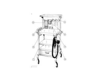
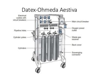
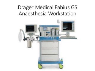
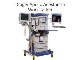
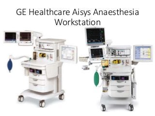
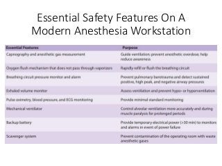
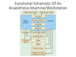


The document provides a comprehensive overview of anaesthesia machines, detailing their history, functions, types, components, and essential safety features. It explains the evolution of these machines from simple devices to modern anaesthesia workstations with sophisticated safety systems and monitoring capabilities. Additionally, it outlines the guidelines for machine obsolescence and the standards that govern their design and safety requirements.


![ANESTHESIA_MACHINE-_PRESSURE_REDUCING_VALVES,_FLOWMETER_AND[1].pptx](https://cdn.slidesharecdn.com/ss_thumbnails/anesthesiamachine-pressurereducingvalvesflowmeterand1-250127121142-c2585726-thumbnail.jpg?width=640&height=640&fit=bounds)


![CTEV [ clubfoot] DR ARUN LAL ,DR MOHAMED ASHRAF travancore medical college k...](https://cdn.slidesharecdn.com/ss_thumbnails/ctevclubfootdrarunlaldrmohamedashraftravancoremedicalcollegekollamkeralaindia-260208063247-18fc466c-thumbnail.jpg?width=640&height=640&fit=bounds)


