Download to read offline


![Page 55
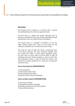
Figure 2-3 Housing topologies given to students
a)Shibam - 16th century Yemen
b) Bruno Taut - Carl Legien Estate [1928] Berlin
c) Patrick Hodgkinson - Brunswick Centre [1972]
d) Microrayon - Soviet Union (Siberia) [20th Century]
e) Fes el Bali - Fes,Morocco
a b
c d
e f
g h
i j
f) Manhattan Commissioners’ Plan - 1811
g) Ildefons Cerda - Example [1859] Barcelona, Spain
h) Kowloon Walled City - Hak Nam - 1898 Hong Kong
i) Hutong courtyard houses - Beijing [15th century]
i) Le Corbusier - Ville Contemporaire [1922] Utopian Planning](https://image.slidesharecdn.com/algorithmicthinking-aparametricapproachtoproblemsolving-230805221304-9c749268/85/ALGORITHMIC-THINKING-A-PARAMETRIC-APPROACH-TO-PROBLEM-SOLVING-55-320.jpg)


![Page 109
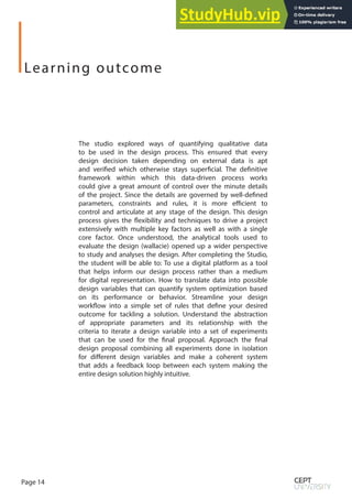
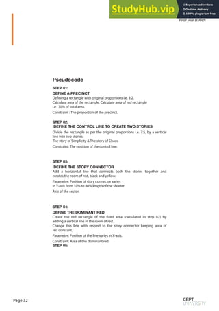
System Logic
Pseudo Code
Parameters
Analysis
Design
Drivers
Evolutionary
Computation
Desired
Solutions
Mutation
Constrains
Iterations
Limitation
Evaluation
Solutions
Emergence
[Fittest Solutions]](https://image.slidesharecdn.com/algorithmicthinking-aparametricapproachtoproblemsolving-230805221304-9c749268/85/ALGORITHMIC-THINKING-A-PARAMETRIC-APPROACH-TO-PROBLEM-SOLVING-109-320.jpg)


This document summarizes an exercise for introducing students to algorithmic thinking and parametric design. The exercise includes: 1) Explaining parametric logic and constraints-based modeling using Grasshopper. 2) Exercises in digitally morphing spatial configurations and decoding Piet Mondrian paintings through iterative rule-based systems. 3) Student works applying these concepts such as deriving shell geometry from cross-referenced points and decoding paintings. The goal is to familiarize students with parametric design techniques, data exchange between physical and digital models, and documenting design experiments.


