Downloaded 258 times

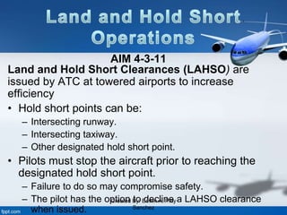
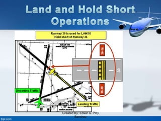
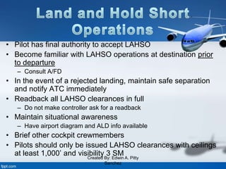
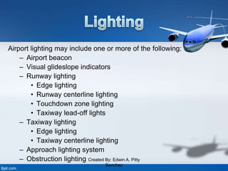
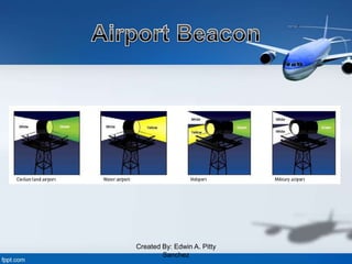
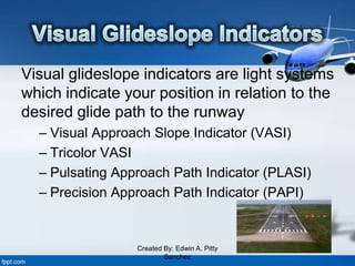
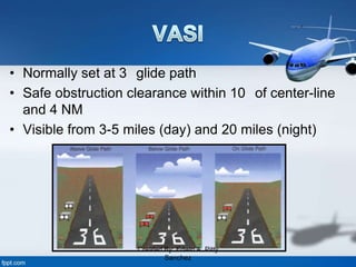
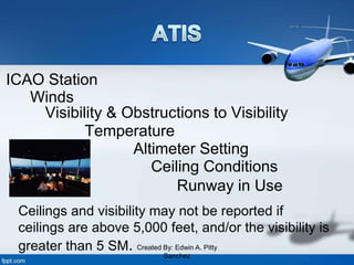


This document discusses several aviation topics including land and hold short operations (LAHSO), airport lighting, visual glideslope indicators, automated terminal information service (ATIS) broadcasts, and runway entrance lights. LAHSO clearances allow aircraft to land and then hold short of an intersecting runway or taxiway to increase airport efficiency. The document outlines pilot responsibilities and safety considerations for LAHSO. It also provides details on common types of airport lighting including approach lighting systems, runway lighting, and visual glideslope indicators to help pilots visualize the glidepath. Lastly, it lists the elements often contained in ATIS broadcasts such as weather, altimeter settings, and runway in use information.


