The document provides guidance on safe practices for operating cryogenic air separation plants. It discusses typical features of air separation units including air compression, contaminant removal, heat exchange, distillation, and expansion. It covers health hazards, plant design considerations, intake air quality, equipment such as compressors, expanders, pumps, coldboxes, control systems, product handling, piping, shutdown procedures, maintenance, and operations. The document aims to inform safe operation of these plants.

![AIGA 056/08
______________________________________________________________________
1
1 Introduction
As a part of a programme of harmonization of industry standards, Asia Industrial Gases Association (AIGA) has
adopted the original Compressed Gas Association (CGA) standard P-8.
This standard is intended as an international harmonized standard for the worldwide use and application by all
members of AIGA, CGA, EIGA and JIMGA. The AIGA edition has the same technical contents as the CGA
edition, however, there are editorial changes primarily in formatting, units used and spelling.
This publication provides guidance on the safe operation of cryogenic air separation plants. It is based on the
experience of the associations ‘member companies that operate cryogenic air separation units (ASUs).
Industrial cryogenic air separation has some potential hazards that must be recognized and addressed. The
hazards include electricity, gases under pressure, very low temperatures, the ability of oxygen to accelerate
combustion, and the asphyxiant properties of nitrogen, argon, and the rare gases [1].1
Cryogenic air separation technology is not static; it has been progressing for many years and will continue to do
so because of engineering development efforts by many associated with the business. Consequently, plant
process cycles, equipment, and operating conditions can be and are of varying kinds. Therefore, this
publication must include some generalized statements and recommendations on matters on which there may
be diversity of opinion or practice. Users of this guide should recognize that it is presented with the
understanding that it cannot take the place of sound engineering judgment, training, and experience. It does
not constitute, and should not be construed to be, a code of rules or regulations.
2 Scope
This guide serves the interest of all who may be associated or concerned with air separation plant operations. It
also serves to acquaint persons not versed in air separation technology with those factors considered important
to safety.
This guide applies to safety in the design, location, construction, installation, operation, and maintenance of
cryogenic air separation plants. Emphasis is placed on equipment and operational and maintenance features
that are peculiar to cryogenic air separation processes. Limited coverage is given to plant equipment such as
air compressors, which are used in other industrial applications and for which safe practices in design,
installation, and use have already been established elsewhere. Further, as this publication is not intended as a
universal safe practices manual for specific design and safety features, it is also important to refer to the
operating manuals of the equipment suppliers.
Cylinder filling facilities, which are an adjunct to some air separation plants, are not covered nor are coverage
extended to facilities involved in rare gas recovery and purification or product transmission piping outside the
plant boundaries.
3 Typical ASU features
All cryogenic ASUs have these features:
– air compression;
– air contaminant removal;
– heat exchanger;
– distillation; and
– expansion (or other refrigeration sources).
1
References are shown by bracketed numbers and are listed in order of appearance in the reference section.](https://image.slidesharecdn.com/aiga05608safepracticesguideforcryogenicairseparationplants-160603134600/85/Aiga-safe-practices-guide-for-cryogenic-air-separation-plants-7-320.jpg)
![AIGA 056/08
______________________________________________________________________
2
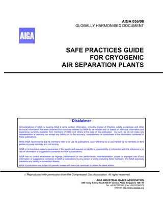
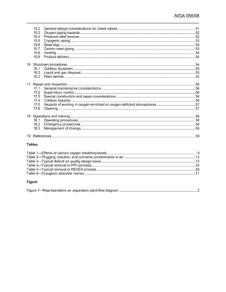
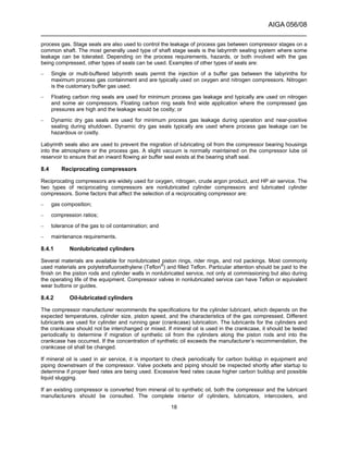
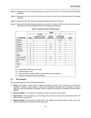
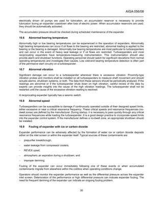
Figure 1 is a typical flow diagram for separating air by cryogenic distillation producing oxygen, nitrogen, and
argon products. Air is compressed in the main air compressor (MAC) to between 4 atm and 10 atm. It is then
cooled to ambient temperature. Trace contaminants such as water, carbon dioxide, and heavy hydrocarbons
are typically removed either in the prepurification unit (PPU) or the reversing heat exchanger (REVEX). The
main heat exchanger cools the air to near its liquefaction temperature before entering the high pressure (HP)
distillation column. Some of the air is reduced in pressure in the expander to produce refrigeration, overcoming
heat leak and process inefficiencies. Gaseous nitrogen from the top of the HP column is condensed by the
reboiler and the liquid used to reflux both columns. Condensing nitrogen releases heat to vaporize liquid
oxygen (LOX) in the low pressure (LP) column sump, which is then taken as product or sent as stripping gas to
the LP column.
Adsorbers
Air
inlet
Direct
contact
after-
coolers
Adsorbers
Waste
Adsorbers
Liquid
oxygen
storage
Liquid
product
Liquid
nitrogen
storage
Liquid
product
Nitrogen product
Oxygen product
Nitrogen
compressor
Oxygen
compressor
Gas storage
Gas storage
Adsorbers Pumps
Pumps
Reflux
valves
Subcooler
Crude
argon
product
Main
air
compressor
Chiller
Waste
chill
tower
Waste
vent
Waste
vent
Low
Expander
High
pressure
column
Liquid
oxygen (alt)
Gaseous
oxygen (alt)
Product liquid
oxygen pump
Nitrogen
liquefier unit
Prepurification
unit
pressure
column
Figure 1—Representative air separation plant flow diagram
Oxygen has the highest boiling point of the three main components and is taken from the bottom of the LP
column. Nitrogen is taken from the top of the LP or HP columns. An argon-rich stream can be withdrawn from
the middle of the LP column and refined to a pure product in other distillation columns. The product streams are
warmed to ambient temperature against incoming air in the main heat exchanger to recover the refrigeration. It
is also possible to remove the products from the distillation system as liquid if sufficient refrigeration is
available. Producing large quantities of liquid products requires extra refrigeration, often supplied by a nitrogen
liquefier unit. Liquid may be stored for pipeline back-up or merchant sales.
There are two typical ASU configurations for producing pressurized oxygen. In the gas plant configuration (also
called gaseous oxygen [GOX] process or classic gas process), oxygen is taken as a vapour from the bottom of
the LP column and warmed by incoming air in the main heat exchanger. If an HP oxygen product is needed, it
is compressed to the required pressure. An LOX purge stream is taken from the sump of the LP column to
prevent the trace contaminants from concentrating above allowable safety limits. In the pumped LOX process
(also known as the internal compression process), oxygen is taken as a liquid from the LP column sump,
pumped to the required pressure, and vaporized in the main exchanger against HP air from the booster air
compressor. The pumped oxygen stream removes trace contaminants from the LP column sump, so a
separate LOX purge stream from the LP column sump may be eliminated.](https://image.slidesharecdn.com/aiga05608safepracticesguideforcryogenicairseparationplants-160603134600/85/Aiga-safe-practices-guide-for-cryogenic-air-separation-plants-8-320.jpg)
![AIGA 056/08
______________________________________________________________________
3
There are many other configurations of the ASU process that are specifically tailored for different products
mixes and customer needs. A detailed discussion of these is beyond the scope of this document.
4 Definitions
4.1 Acid gas
Air contaminants such as chlorine, NOx, and SOx that can form acid when combined with water.
NOTE—Acid gases can create corrosive conditions in brazed aluminium heat exchangers (BAHXs) and other equipment.
4.2 Adsorption
Purification process in which one or more components from a gas or liquid is preferentially adsorbed onto a
solid desiccant or other adsorbent.
NOTE—Typical adsorbents include:
– Molecular sieve—granular adsorbent (typically 13X) used in air PPUs for water, carbon dioxide, and hydrocarbon
removal;
– Alumina—granular adsorbent typically used in air PPUs or dryers for water removal; and
– Silica gel—granular adsorbent typically used in cryogenic adsorbers for carbon dioxide and hydrocarbon removal.
4.3 Asphyxiation
To become unconscious or die from lack of oxygen.
4.4 Blowout
Maintenance or commissioning procedure in which a fluid is blown through piping and equipment to eliminate
dirt, moisture, or other impurities.
4.5 Brazed aluminium heat exchanger (BAHX)
An aluminium plate and fin heat exchanger consisting of corrugated sheets separated by parting sheets and an
outer frame consisting of bars with openings for the inlets and outlets of fluids, equipped with headers and
nozzles to connect to external piping.
NOTE—The approximate thickness of the corrugated sheets is 0.2 mm to 0.5 mm, while the parting sheets have
thicknesses between 1.0 mm and 2.4 mm. More information is provided in AIGA057/08 Safe Use of Brazed Aluminium Heat
Exchangers for Producing Pressurized Oxygen [2].
4.6 Casing
Outside walls of a coldbox or cryogenic piping duct. The cross section can be circular or rectangular.
4.7 Catalyst
Material that helps promote a reaction but is not changed itself.
4.8 Cavitation
Undesirable vapour bubble formation and subsequent bubble collapse of a saturated or slightly subcooled
liquid in a pump that can cause loss of prime and damage the pump.
4.9 Centrifugal
Dynamic compressor or pump that works by accelerating a fluid in a rotating impeller with subsequent
conversion of this energy into pressure.
4.10 Cleanup
Removing trace contaminants from a stream or from process equipment.
4.11 Coldbox
Structure that contains cryogenic distillation columns, other process equipment, piping, and insulation; can also
refer to the cryogenic portion of an ASU.](https://image.slidesharecdn.com/aiga05608safepracticesguideforcryogenicairseparationplants-160603134600/85/Aiga-safe-practices-guide-for-cryogenic-air-separation-plants-9-320.jpg)
![AIGA 056/08
______________________________________________________________________
6
4.33 Instrumented system
System typically composed of sensors (for example, pressure, flow, temperature transmitters), logic solvers or
control systems (for example, programmable controllers, distributed control systems), and final elements (for
example, control valves) designed to perform a specific function.
NOTE—For more information, see IEC 61511, Functional Safety–Safety Instrumented Systems for the Process Industry
Sector—Part 1: Framework, Definitions, System, Hardware and Software Requirements [3].
4.34 Joule–Thompson (JT) expansion
Process by which a fluid is expanded adiabatically (no work removed) from high pressure to lower pressure,
usually through a valve.
NOTE—For gas applications in air separation plants, this results in a temperature drop.
4.35 Labyrinth
Type of gas seal that uses a series of teeth to minimize leakage of the process fluid.
4.36 Lockout
Condition where a device cannot be operated without a wilful, conscious action to do so to ensure safety by
positively isolating energy sources (pressure, electrical, temperature, and chemical).
NOTE— An example is when electricity is turned off and cannot be regained without removing a protective device such as a
padlock from the actuating device. Another example is a valve where the handle is removed and stored securely until it is
safe to operate the valve. A locked-out device shall be immediately tagged out.
4.37 Lower explosive limit (LEL)
Lowest concentration of a flammable gas in an oxidant that will propagate when ignited.
NOTE—LEL is sometimes referred to as lower flammability limit (LFL).
4.38 Material safety data sheets (MSDSs)
Documents describing a material and its associated hazards mandated by the government and made available
by the material supplier.
4.39 Net positive suction head (NPSH)
Margin of difference (measured in height) between the actual pressure of a liquid flowing into a pump and the
vapour pressure of the liquid.
4.40 Nitrogen NF
Nitrogen that meets United States Pharmacopeia and National Formulary (USP–NF) requirements [4].
NOTE—See CGA G-10.1, Commodity Specification for Nitrogen, for additional information [5].
4.41 Nozzle
Pipe connected to any vessel.
4.42 Oxygen-deficient atmosphere/nitrogen-enriched atmosphere
Atmosphere in which the oxygen concentration by volume is less than 19.5%.
4.43 Oxygen-enriched atmosphere
Atmosphere in which the oxygen concentration exceeds 23.5%.
4.44 Oxygen USP
Oxygen that meets USP–NF requirements [4].
NOTE—See CGA G-4.3, Commodity Specification for Oxygen, for additional information [6].
4.45 Pot boiling
See 4.15.](https://image.slidesharecdn.com/aiga05608safepracticesguideforcryogenicairseparationplants-160603134600/85/Aiga-safe-practices-guide-for-cryogenic-air-separation-plants-12-320.jpg)
![AIGA 056/08
______________________________________________________________________
7
4.46 Pool boiling
See 4.15.
4.47 Precipitate
Formation of a solid from a liquid or vapour solution when the solubility limit for a component is exceeded.
4.48 Pressure relief device (PRD)
Self-contained device designed to protect a vessel or piping from achieving pressures higher or lower (vacuum)
than its design to avoid failure of the piping or vessel; includes safety relief valves and rupture disks.
4.49 Purge
Elimination of an undesirable contaminant by displacement with another fluid.
NOTE—A nitrogen purge of process equipment prevents the contact of moisture with cryogenic equipment. LOX containing
hydrocarbons is purged from the reboiler sump with clean LOX.
4.50 Reciprocating
Positive displacement-type compressor, expander, or pump that uses pistons.
4.51 Regeneration
Reactivation of a spent or loaded adsorbent vessel using a hot and/or LP gas.
4.52 Safe area
Location where exhaust gases can be discharged safely causing no harm to personnel or property.
NOTE—A safe area is also a place where surrounding materials are compatible with the exhaust gas.
4.53 Safety instrumented system (SIS)
System used to implement one or more functions necessary to prevent a hazard from arising and/or to mitigate
its consequences.
NOTE—An SIS is composed of any combination of sensors (for example, pressure, flow, temperature transmitters), logic
solvers or control systems (for example, programmable controllers, distributed control systems), and final elements (for
example, control valves). Use of the term SIS implies IEC 61511 has been used to design, operate, and maintain the safety
system [3].
4.54 Safety permits
Procedural documents highlighting special safety considerations that are issued to allow work to commence in
a specific location.
4.55 Solubility
Amount of a component that can remain dissolved in a liquid or vapour without precipitating out as a solid.
4.56 Structured packing
Sheets of corrugated metal arranged in a distillation column to promote intimate contact between vapour
flowing upward with liquid flowing downward.
4.57 Sump
Bottom of a distillation column or other vessel that can contain a liquid inventory, hold-up, or reserve level.
4.58 Tagout
Written notification that a piece of equipment is out of service and cannot be operated without clearance from
authorized personnel.
NOTE—Equipment that has been tagged out typically has a paper tag attached directly to it indicating that the item is out of
service.
4.59 Upper explosive limit (UEL)
Highest concentration of a flammable gas in an oxidant that will propagate when ignited.](https://image.slidesharecdn.com/aiga05608safepracticesguideforcryogenicairseparationplants-160603134600/85/Aiga-safe-practices-guide-for-cryogenic-air-separation-plants-13-320.jpg)
![AIGA 056/08
______________________________________________________________________
8
NOTE—UEL is sometimes referred to as upper flammability limit (UFL).
5 Health hazards
Some health hazards are directly associated with the compressed gas industry. Properties of certain gas
products subject personnel to extreme cold temperatures, oxygen-deficient (asphyxiating) atmospheres, or
oxygen-enriched (increased fire risk) atmospheres. Proper precautions, a basic knowledge of the behaviour of
these materials, and wearing proper protective equipment can minimize exposure to these hazards. Refer to
the producer's material safety data sheets (MSDSs) for specific information on materials handled in air
separation plants.
5.1 Cryogenic liquids
The products of a cryogenic air separation plant have associated hazards such as:
– Cryogenic injuries or burns resulting from skin contact with very cold vapour, liquid, or surfaces. Effects are
similar to those of a heat burn. Severity varies with the temperature and time of exposure. Exposed or
insufficiently protected parts of the body can stick to cold surfaces due to the rapid freezing of available
moisture, and skin and flesh can be torn on removal;
– Risk of frostbite or hypothermia (general body and brain cooling) in a cold environment. There can be
warning, in the case of frostbite, while the body sections freeze. As the body temperature drops, the first
indications of hypothermia are bizarre or unusual behaviour followed, often rapidly, by loss of
consciousness;
– Respiratory problems caused by the inhalation of cold gas. Short-term exposure generally causes
discomfort; however, prolonged inhalation can result in effects leading to serious illness such as pulmonary
edema or pneumonia; and
– Hazardous concentrations and/or reduced visibility can also occur at considerable distances from the point
of discharge, depending on topography and weather conditions. Cold gases are heavier than air, tend to
settle and flow to low levels, and can create a dense water vapour fog.
See CGA P-12, Safe Handling of Cryogenic Liquids, for additional details [7].
5.2 Gas products
Nitrogen and argon are simple asphyxiants and if present in sufficient quantity can reduce the oxygen in the
local atmosphere below that required to support life. If there are any appreciable quantities of hydrocarbon
contaminants, there can be some nausea, narcosis, or dizziness. Removal from exposure generally results in
return to normal body and behavioural functions. Oxygen-enriched atmospheres increase susceptibility to
ignition and combustibility rates can be many times that of normal atmospheres.
5.3 Asphyxiation
The normal oxygen concentration in air is approximately 21% by volume. In the US gas containing less than
19.5% oxygen constitutes a hazardous working environment as defined by Title 29 of the U.S. Code of Federal
Regulations (29 CFR) Part 1910.146 [8]. The depletion of the quantity of oxygen in a given volume of air by
displacement with an inert gas is a potential hazard to personnel (see AIGA 008/04 Hazards of Inert Gases
{10]. Also see the EIGA documents concerning the campaign against asphyxiation [82,83] and other
sources.[9, 11,12,13]
When the oxygen content of air is reduced to approximately 15% or 16%, the rate of burning of combustible
materials significantly decreases. The flame of ordinary combustible materials including those commonly used
as fuel for heat or light is extinguished. This can be the first indication of an oxygen-deficient hazard. Somewhat
less than this concentration an individual breathing the atmosphere is mentally incapable of diagnosing the
situation. The symptoms of sleepiness, fatigue, lassitude, loss of coordination, errors in judgment, and
confusion are masked by a state of euphoria giving the victim a false sense of security and well being. See
Table 1 for other typical symptoms of oxygen-deficient atmospheres [9].](https://image.slidesharecdn.com/aiga05608safepracticesguideforcryogenicairseparationplants-160603134600/85/Aiga-safe-practices-guide-for-cryogenic-air-separation-plants-14-320.jpg)
![AIGA 056/08
______________________________________________________________________
9
Human exposure to atmospheres containing 12% or less oxygen brings about unconsciousness without
warning and so quickly that individuals cannot help or protect themselves. This is true if the condition is
reached either by immediate change of environment or by gradual depletion of oxygen. The individual's
condition and degree of activity has an appreciable effect on signs and symptoms at various oxygen levels. In
some cases, prolonged reduction of oxygen can cause brain damage even if the individual survives.
Table 1—Effects at various oxygen breathing levels
Oxygen percent at sea level
(atmospheric pressure = 760 mmHg) Effects
20.9 Normal
19.0
Some adverse physiological effects occur, but they are
unnoticeable.
16.0
Increased pulse and breathing rate. Impaired thinking and
attention. Reduced coordination.
14.0
Abnormal fatigue upon exertion. Emotional upset. Faulty
coordination. Poor judgment.
12.5
Very poor judgment and coordination. Impaired respiration that
may cause permanent heart damage. Nausea and vomiting.
<10
Inability to perform various movements. Loss of consciousness.
Convulsions. Death.
NOTES
1 Adapted from ANSI Z88.2, Respiratory Protection [14].
2 These indications are for a healthy average person at rest. Factors such as individual health (such as being a
smoker), degree of physical exertion, and high altitudes can affect these symptoms and the oxygen levels at which
they occur.
Areas where it is possible to have low oxygen content shall be well ventilated. Inert gas vents should be piped
outside of buildings or to a safe area. Where an oxygen-deficient atmosphere is possible, special precautions
such as installation of oxygen analyzers with alarms, ensuring a minimum number of air changes per hour,
implementing special entry procedures, or a combination of these procedures shall be taken. Warning signs
shall be posted at all entrances to alert personnel to the potential hazard of an oxygen-deficient atmosphere.
Oxygen analyzer sensors should be located in positions most likely to experience an oxygen-deficient
atmosphere and the alarm should be clearly visible, audible, or both at the point of personnel entry.
When there is any doubt of maintaining safe breathing atmosphere, self-contained breathing apparatus or
approved air lines and masks should be used, particularly when personnel enter enclosed areas or vessels.
Breathing air should come from a qualified independent source; a plant instrument air system shall not be used
as a source of breathing air.
Personnel working in or around oxygen-deficient atmospheres shall use proper procedures including confined
space entry.
DANGER: Entering an area with an oxygen-deficient atmosphere without following proper procedures will
result in serious injury or death.
5.4 Oxygen hazards
Oxygen concentrations higher than 23.5% create fire hazards but not asphyxiation hazards. Oxygen is not
combustible, but it promotes very rapid combustion of flammable materials and some materials that are
normally regarded as being relatively nonflammable. Although a source of ignition energy is always necessary
in combination with flammable materials and oxygen, control or elimination of flammables is a precautionary
step. Lubricating oils and other hydrocarbon materials can react violently with pure oxygen and the combination
shall be avoided.](https://image.slidesharecdn.com/aiga05608safepracticesguideforcryogenicairseparationplants-160603134600/85/Aiga-safe-practices-guide-for-cryogenic-air-separation-plants-15-320.jpg)
![AIGA 056/08
______________________________________________________________________
10
Personnel should not be exposed to oxygen-enriched atmospheres because of increased risks of fire. As
concentrations increase above 23.5% oxygen, ease of ignition of clothing increases dramatically. Once ignited
by even a relatively weak ignition source such as a spark or cigarette, clothing can burst into flame and burn
rapidly. Above 60% oxygen, the nap on clothing and even body hair and oil are subject to flash fire that spreads
rapidly over the entire exposed surface.
Areas where it is possible to have high oxygen content shall be well ventilated. Gas vents shall be piped
outside of buildings or to a safe area. Where an oxygen-enriched atmosphere is possible, special precautions
such as installation of oxygen analyzers with alarms, ensuring a minimum number of air changes per hour,
implementing special entry procedures, or a combination of these procedures shall be taken. Warning signs
shall be posted at all entrances to alert personnel to the potential hazard of an oxygen enriched atmosphere.
For additional information on oxygen hazards see AIGA 005/04 Fire Hazards of Oxygen & Oxygen Enriched
Atmospheres [15].
5.5 Protective clothing
Proper clothing and special equipment can serve to reduce fire hazards when working with oxygen or burns
when working with cryogenic liquids or gases, but prevention of the hazard should be the primary objective.
Insulated or leather gloves (untanned and oil-free for oxygen service) should be worn when handling anything
that is or might have been cooled with cryogenic liquids or when participating in liquid loading and unloading
activities. Gloves shall fit loosely so they can be removed easily if liquid splashes on or in them.
A face shield or chemical splash goggles shall be worn at all times when handling cryogenic liquids.
Clothing should have minimum nap. There are a number of flame retardant materials available such as
Nomex®
for work clothing, but they can burn in high-oxygen atmospheres. There is some advantage in these
materials as most of them would be self-extinguishing when removed to normal air atmospheres. All clothing
should be clean and oil-free. No means of ignition should be carried. Footwear should not have nails or
exposed metallic protectors that could cause sparking.
If individuals inadvertently enter or are exposed to an oxygen-enriched atmosphere, they shall leave as quickly
as possible. Avoid sources of ignition. Do not smoke for at least one-half hour. Opening the clothing and
slapping it helps disperse trapped vapours.
6 General plant considerations
6.1 Site selection
Air separation plant safety should begin with a safety evaluation of the proposed plant site. Generally, air
separation plants are located in or near industrial areas as an adjunct to other industrial or chemical plants. A
plant installation should conform to the applicable industry consensus standards as well as all applicable
national regulations.
The plant operation should be reviewed for compatibility with the surrounding area. The potential hazard of the
cooling tower or cryogenic fog to nearby plants or vehicular traffic should be recognized. Adequate space
should be provided for cryogenic liquid disposal.
6.2 Safety factors in plant layouts
The use of valve pits, trenches, or both for cryogenic gas or liquid piping systems is not recommended because
oxygen-enriched or oxygen-deficient atmospheres can occur very easily with such installations. If gas and
liquid piping systems are installed in enclosed spaces, precautionary measures such as forced ventilation and
alarm systems are recommended. Appropriate warning signs shall be posted.
Oxygen-rich liquid drain lines should not be installed in a trench. Over time, trenches can accumulate oil,
grease, and trash or other debris. If a leak in the line develops, a fire could result.
Caution should be taken to prevent liquid spills from entering floor drains or sewer systems.](https://image.slidesharecdn.com/aiga05608safepracticesguideforcryogenicairseparationplants-160603134600/85/Aiga-safe-practices-guide-for-cryogenic-air-separation-plants-16-320.jpg)
![AIGA 056/08
______________________________________________________________________
11
6.3 Materials of construction
The materials used in an air separation plant are exposed to a wide range of temperatures, pressures, and
purities during operation. Materials shall be selected that are compatible with the expected conditions including
normal operation, startup, shutdown, and process upsets.
For an oxygen system to operate safely, all parts of the system should be reviewed for compatibility with
oxygen under all conditions they encounter [16, 17]. The system shall be designed to prevent oxygen
combustion by:
– selecting proper material;
– operating within the designed pressure, temperature, and flow limits; and
– obtaining/maintaining proper cleanliness.
Substitution of materials should not be made without first consulting a qualified engineering source. The vendor
supplying the material can also be contacted for pertinent information.
6.3.1 Metals
While common construction materials such as carbon steel, aluminium, and copper are used extensively in
fabricating air separation plant components, it is important to remember that the use of these materials is
selective and must be compatible with the operating conditions [17]. For example, common carbon steel is not
used at temperatures less than −20 °F (−29 °C) because at these temperatures it loses ductility, becomes
brittle, and is subject to failure under impact conditions. Some metals that can be used safely in temperatures
less than –20 °F (–29 °C) are austenitic stainless steel, aluminium, copper, Monel, brass, silicon-copper, and
9% nickel (ASTM A-353 steel). Reference information on the use of metals includes stainless steel, aluminium,
copper, Monel, and brass [18 - 25].
Because of cost, carbon steel is generally used in temperatures greater than –20 °F (–29 °C) and at ambient
temperature conditions for interconnecting process piping, storage vessels, and pipelines for either oxygen, air,
or any of the inert gases such as argon or nitrogen [26, 27]. In special cases such as when moisture is present,
stainless steel or some other equally suitable metal should be considered to prevent corrosion.
6.3.2 Nonmetals
Nonmetallic materials such as gaskets, valve packing, insulation, and lubricants shall be carefully checked to
determine if they can be used for a particular application [28]. All factors associated with their use such as
temperature, pressure, etc., shall be considered in deciding if a material can be used without decreasing the
design safety integrity of an oxygen system. In an oxygen system the quantity of nonmetallic materials should
be kept to a minimum and, where possible, should be kept out of the direct flow of the gas stream.
6.4 Insulation—other than coldbox
Interconnecting process lines between components of an air separation plant operating at low temperatures
require insulation to reduce process heat leak to an acceptable minimum and to prevent exposure of personnel
to extremely low temperatures. The temperature and service of the line determine the type of insulation used.
Insulation for LOX lines or other lines that might come in contact with LOX should be noncombustible to protect
against a possible reaction in the event of a liquid leak. Other process lines operating at temperatures warmer
than the liquefaction point of air, approximately –313 °F (–192 °C), may be insulated with any commercially
acceptable insulation that meets design requirements. Insulation that is noncombustible in air should be given
preference. Oxygen-compatible binders, sealing compounds, and vapour barriers should be used on lines
carrying oxygen or oxygen-enriched gases or liquids.
Process lines operating at temperatures colder than the liquefaction point of air should be insulated with
material compatible with oxygen. If the insulation cracks or deteriorates at these temperatures, air is diffused](https://image.slidesharecdn.com/aiga05608safepracticesguideforcryogenicairseparationplants-160603134600/85/Aiga-safe-practices-guide-for-cryogenic-air-separation-plants-17-320.jpg)
![AIGA 056/08
______________________________________________________________________
12
into the insulation, condenses against the surface of the pipe, and exposes the insulation material to oxygen-
enriched liquid.
Personnel should be protected from hot lines (greater than 140 °F [60 °C]) by either insulating the line or
preventing access while the line is hot.
6.5 Cleaning
All materials for use in or interconnected with oxygen systems should be suitably cleaned before the system is
put into service. Mill scale, rust, dirt, weld slag, oils, greases, and other organic material shall be removed. An
improperly cleaned line in oxygen service can be hazardous because particulates, greases, oils, and other
organic materials can ignite a fire. Fabrication and repair procedures should be controlled to minimize the
presence of such contaminants and thereby simplify final cleaning procedures. See AIGA 012/04, Cleaning of
Equipment for Oxygen Service, CGA G-4.1, Cleaning Equipment for Oxygen Service and ASTM G93, Standard
Practice for Cleaning Methods and Cleanliness Levels for Material and Equipment Used in Oxygen-Enriched
Environments [29, 30, 31].
Cryogenic process equipment and piping that handle inert fluids should be cleaned for oxygen service. This
prevents foreign material from reaching other parts of the ASU.
6.6 Electrical requirements
Applicable codes shall be followed. In the US, air separation plants are not considered hazardous locations for
electrical equipment as defined by Article 500 of NFPA 70, National Electrical Code®
[32]. Europe is in the
same situation Therefore, general purpose or weatherproof types of electrical wiring and equipment are
acceptable depending on whether the location is indoors or outdoors.
In areas where high oxygen concentrations could be expected, electrical equipment with open or unprotected
make-and-break contacts should be avoided. The simple expedient of locating electrical equipment away from
areas where high oxygen concentrations can occur eliminates potential hazards in these situations.
Some plants might have specific areas or equipment such as a refrigeration system using a hydrocarbon or
ammonia refrigerant or one including an argon purification unit involving the use and handling of hydrogen that
necessitate special consideration. In these cases, the design considerations specified in the appropriate
industry codes should be followed.
6.7 Noise
The noise produced by compressors and their drives; by expansion turbines; by high gas velocities through
piping and valves; and by pressure relief valves, vents, or bypasses shall be considered from the standpoint of
potential hazard of hearing damage to employees. To assess the hazard, noise surveys should be performed
after initial inspection or when modifications are made that could change the noise emitted [33 - 37]. Noise
abatement and use of personnel ear protection shall follow national government guidelines available (In US, 29
CFR Part 1910.95 is followed [8]).
New equipment and varying operating conditions require a continuing program of noise level surveillance.
Periodic audiometric checks of personnel might be necessary depending on exposure times and noise levels.
7 Intake air quality
Air quality can have an impact on the air separation plant site selection and should be carefully evaluated. The
air separation plant typically is located in an industrial area and thus some degree of contamination released
from industrial and/or chemical plant operations can be expected to be present in the air. Trace contaminants in
the atmospheric air, particularly hydrocarbons, have a direct bearing on the safe operation of an air separation
plant. It is important to identify these contaminants and their levels of concentration in the atmospheric air.
Short-term air quality analysis might not be representative of long-term air contaminant levels. Changing site
conditions can have an impact on air quality and should be evaluated periodically or when the surrounding
industries change.](https://image.slidesharecdn.com/aiga05608safepracticesguideforcryogenicairseparationplants-160603134600/85/Aiga-safe-practices-guide-for-cryogenic-air-separation-plants-18-320.jpg)
![AIGA 056/08
______________________________________________________________________
13
7.1 Contaminants
Trace contaminants can be put into three main categories based on the potential problems they cause in the
ASU (plugging, reactive, or corrosive) as shown in Table 2. See 9.1, which describes in detail how each of the
contaminants in Table 2 is dealt with within the ASU process.
Table 2—Plugging, reactive, and corrosive contaminants in air
Plugging Reactive Corrosive
Chemical name Symbol Chemical name Symbol Chemical name Symbol
Water H2O Methane CH4 Sulphur dioxide SO2
Carbon dioxide CO2 Acetylene C2H2 Sulphur trioxide SO3
Nitrous oxide N2O Ethylene C2H4 Hydrogen sulphide H2S
Ethane C2H6 Chlorine Cl2
Propylene C3H6 Hydrochloric acid HCl
Propane C3H8 Ammonia NH3
Other hydrocarbons Other sulphur compounds
Oxides of nitrogen NOx Other chlorides
Ozone O3
NOTE⎯This table was originally developed for AIGA 035/06, Safe Operation of Reboilers/Condensers in Air Separation Units
[38].
Plugging contaminants concentrate, precipitate out as a solid, or both in the ASU process. While plugging is an
operating problem, it can also lead to dry boiling or pool boiling, which can in turn concentrate the reactive
contaminants to form flammable mixtures. The plugging contaminants of most concern are water, carbon
dioxide, and nitrous oxide.
Reactive contaminants can concentrate within the ASU and form flammable mixtures with oxygen or enriched
air. The most important reactive contaminants in air are methane, ethane, ethylene, acetylene, propane, and
propylene. The other higher boiling hydrocarbons are typically treated together. Hydrocarbon aerosols from
smoke and haze are a special type of reactive contaminant and are discussed in 7.5. NOx and ozone are also
reactive, but are not a major concern in properly operated ASUs.
The previously discussed contaminants concentrate in oxygen. Hydrogen and carbon monoxide concentrate in
nitrogen, waste nitrogen product, or both and are generally not safety hazards.
Corrosive contaminants (acid gases and ammonia) can react with equipment and piping causing operating
problems and reduced plant life. Since this document is primarily dealing with safety, these are not discussed in
as much detail as the plugging and reactive components.
Table 3 is a typical default air quality design basis that in the absence of other data can be used as the
maximum simultaneous concentrations in the air intake to an ASU. Changes to the designs of various ASU
components might be required if these concentrations are exceeded. Actual data for the locality should be
provided to the ASU supplier whenever such information is available.
Table 3⎯Typical default air quality design basis
Contaminants Design air quality (ppm/v)
Acetylene 0.3
Carbon dioxide 400
C4 + hydrocarbons 1
Ethane 0.1
Ethylene 0.1](https://image.slidesharecdn.com/aiga05608safepracticesguideforcryogenicairseparationplants-160603134600/85/Aiga-safe-practices-guide-for-cryogenic-air-separation-plants-19-320.jpg)
![AIGA 056/08
______________________________________________________________________
14
Methane 5
NOx (nitric oxide and nitrogen dioxide) 0.1
Nitrous oxide 0.35
Propane 0.05
Propylene 0.2
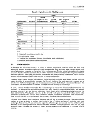
7.2 Reactive contaminants that concentrate in oxygen
Hydrocarbons and most other reactive contaminants have boiling temperatures higher than that of oxygen.
They concentrate in the oxygen-enriched liquids found in the sumps of columns and reboilers. The primary
hazard is that the hydrocarbons concentrate in LOX. If these contaminants concentrate to the lower LEL, a
reaction with oxygen can occur. The LEL of hydrocarbons in GOX is between 5% and 10% when expressed as
methane equivalent, and the LEL in LOX is slightly higher [39].
The specific hazards of each hydrocarbon are listed in the following paragraphs:
– Methane is slightly less volatile than oxygen and is completely soluble in LOX. It is somewhat difficult to
concentrate methane to unsafe levels in most ASU processes;
– Ethane’s volatility and solubility in LOX, while less than methane, poses no significant potential to
concentrate to unsafe levels or form a second liquid phase provided that an adequate liquid purge is
maintained on the reboiler sump;
– Ethylene presents a special hazard because it can precipitate as a solid under some ASU operating
conditions, primarily when boiling LOX below 44 psia (3 bara) (see AIGA 057/08) [2]. If an ethylene source
is nearby, consideration should be given to plant design to ensure that ethylene remains within safe limits
either by changing the process, adding analytical instrumentation, or increasing the liquid purge on the
reboiler sump;
– Acetylene is a very hazardous reactive contaminant. Because acetylene has a low solubility in LOX, if it
enters the coldbox it concentrates in LOX and precipitates out as a solid at concentrations as low as
4 ppm to 6 ppm (depending on the LOX pressure). The solid is relatively unstable and requires little energy
to ignite. ASUs equipped with PPUs remove all of the acetylene from the air so none enters the coldbox.
Plants equipped with REVEX do not remove acetylene from the incoming air and shall deal with it in the
coldbox, typically by using cryogenic adsorbers;
– Propane is a relatively hazardous hydrocarbon because of its low volatility relative to oxygen and its ability
to form a second liquid phase if its concentration is high enough. At low pressures, the second liquid phase
forms before its concentration in LOX reaches the LEL. This second liquid phase of relatively pure propane
could then react with the oxygen-rich phase, if ignited. Propane is not removed by the REVEX and is only
partially removed by the PPU; the remainder shall be removed by liquid purge;
– Propylene is similar to propane in that it forms a second liquid phase in LOX if its concentration is high
enough. This second liquid phase is reactive. Propylene, however, is removed relatively easily either by
PPUs or cryogenic adsorption;
– Other hydrocarbons are the higher boiling hydrocarbons (C4+). As the molecular weight increases, the
solubility in LOX decreases. However, these are dealt with relatively easily by all trace contaminant-
removal systems provided that these systems are operated properly;
– NOx can react with oxygen, but is removed either by the PPU or cryogenic adsorption. NOx compounds are
primarily nitric oxide and nitrogen dioxide in atmospheric air and are the by-products of incomplete
combustion. If they enter the coldbox, nitric oxide and nitrogen dioxide form increasingly higher molecular
weight NOx compounds (nitrogen trioxide, di-nitrogen tetraoxide, and di-nitrogen pentoxide), which can
then precipitate and plug equipment. At cold temperatures, NOx compounds can react with any
unsaturated dienes found in REVEXs to form explosive gums [40, 41, 42]; and
NOTE—NOx (nitric oxide and nitrogen dioxide) are different compounds than nitrous oxide.](https://image.slidesharecdn.com/aiga05608safepracticesguideforcryogenicairseparationplants-160603134600/85/Aiga-safe-practices-guide-for-cryogenic-air-separation-plants-20-320.jpg)
![AIGA 056/08
______________________________________________________________________
15
– Ozone is unstable and decomposes to oxygen-releasing heat, which is a potential hazard. Ozone is
removed either by PPU or cryogenic adsorption.
7.3 Reactive contaminants that concentrate in nitrogen
Hydrogen and carbon monoxide have boiling points lower than oxygen and thus concentrate in nitrogen. The
concentration factor is typically only 2 times to 10 times, so they remain at low ppm concentration. Hydrogen
and carbon monoxide are a purity issue when ultra high purity nitrogen is produced. Carbon monoxide is also
an issue when nitrogen NF is produced. They shall be removed by other means such as front-end catalytic
oxidation or nitrogen purification.
7.4 Plugging components
Characteristics of the specific plugging components are as follows:
– Water is very insoluble in cryogenic fluids and shall be completely removed before reaching the distillation
columns. Water is completely removed in the REVEX or PPU;
– Carbon dioxide is relatively insoluble in LOX and is removed by the PPU, REVEX, or cryogenic
adsorption. Reboiler liquid purge flows can assist in maintaining carbon dioxide concentrations below the
safe limit in the reboiler sump (see AIGA 035/06) [38]; and
– Nitrous oxide is relatively insoluble in LOX; however, it is more soluble than carbon dioxide. Therefore, for
most applications, no nitrous oxide removal is required. It is partially removed by standard PPUs but
special designs of the PPU can increase the removal efficiency. It is also removed by cryogenic adsorption.
Reboiler liquid purge flows can assist in maintaining nitrous oxide concentrations below the safe limit in the
reboiler sump [38, 43].
NOTE—NOx (nitric oxide and nitrogen dioxide) are different compounds than nitrous oxide.
The solubility limits of mixtures of nitrous oxide and carbon dioxide in liquid cryogens are lower than their single
component limits when both are present because they form a solid solution (see 12.10).
7.5 Haze and smoke from fires
Haze and smoke from forest fires, burning farmland, or other biomass combustion can create significant
hazards for ASUs. Analysis of one area shows that the emissions from a forest fire consist of vapour
components of n-alkanes, aromatics, and some oxygen-containing compounds, of C3 to C21 hydrocarbons and
aerosols composed of droplets of 0.1 µ to 2 µ in diameter, mainly C8 to C36 hydrocarbons [44].
Only the vapour compounds are adsorbed by a PPU; however, the aerosols are typically too small to be
retained by inlet air or PPU dust filters, which typically capture particles 2 µ to 5 µ and larger. The aerosols
accumulate in the reboiler sump and over time can become a significant hazard.
Running an ASU in a haze/smoke environment for many days or weeks can present a significant hazard. In
most cases, the probability of such an event is low and no extra design precautions need to be taken. However,
if such conditions are possible, high-efficiency filtration might be needed to prevent aerosols from entering the
coldbox. The location of the filters can be on the MAC suction or immediately prior to the ASU.
If an ASU operates in a haze/smoke environment and is not designed to handle a high level of aerosols, the
liquid purge rate should be increased as much as is practical. The ASU should be monitored very carefully for
any sign of potential accumulation such as increased pressure drops, plugged screens, increased reboiler
temperature difference, and higher reboiler sump hydrocarbon concentration. Depending on the duration and
severity of the haze condition, consideration should be given to shutting down the ASU, performing a derime, or
both.
NOTE—Meilinger reports that derime is not effective in removing aerosols [45].](https://image.slidesharecdn.com/aiga05608safepracticesguideforcryogenicairseparationplants-160603134600/85/Aiga-safe-practices-guide-for-cryogenic-air-separation-plants-21-320.jpg)
![AIGA 056/08
______________________________________________________________________
17
and centrifugal compressors, and positive displacement machines, which include reciprocating, diaphragm,
rotary, and screw types.
8.1 Axial compressors
Axial compressors are commonly used for the MAC on large ASUs. When axial compressors are used,
consideration should be given to the dynamic performance characteristics of the compressor with particular
emphasis on surge conditions. A rigorous torsional and lateral critical review of the entire compressor-gear-
drive system is required. The use of one or more rows of variable stator blades for controlling compressor
capacity is common. Consideration should be given to the design of the stator blade actuating mechanism with
emphasis on the prevention of rusting and dirt deposits on it, which can cause binding in operation. Special
consideration should also be given to the first three rows of rotating blades where moisture can cause rusting
and imbalance. The compressor casing should be designed for the maximum possible pressure that can be
reached under any condition of operation including surge. Safety standards for compressors are covered in
ASME B19.1, Safety Standard for Air Compressor Systems, and ASME B19.3, Safety Standard for
Compressors for Process Industries [46, 47].
8.2 Centrifugal compressors
Centrifugal compressors are widely used for MAC duty as well as oxygen product, nitrogen product, and
nitrogen recycle service. As with the axial machine, careful consideration should be given to the performance
characteristics compared to the expected plant operating requirements. A review of the torsional and lateral
criticals with the gear and driver included should be performed for each installation. Compressor casings
should be designed for the maximum possible pressure that can be reached under any condition of operation
including surge. Capacity control is typically accomplished by variable inlet guide vanes on at least the first
stage.
8.3 Other dynamic compressor considerations
8.3.1 Antisurge control
All axial and centrifugal compressors shall be equipped with an automatic antisurge control system with either a
suitable bypass or blow-off valve. The response time of the antisurge system should be consistent with the
dynamics of the process system.
8.3.2 Check valve
A check valve shall be installed in the discharge line immediately after the vent or recirculation bypass
connection of all dynamic compressors to prevent surge and reverse rotation. In wet gas service, moving parts
should be made of nonrusting material to ensure proper operation of the valve.
8.3.3 Monitoring devices
The manufacturer’s recommendations shall be followed for monitoring operating parameters, alarms, and
shutdowns.
Proximity-type vibration probes and monitors shall be installed on all axial or centrifugal compressor
installations to measure shaft movement and actuate alarm and shutdown systems. The data from these
sensors should be periodically analyzed. If the readings are abnormal or if the compressor shuts down on high
vibration, careful review of the data by experts can provide insights into the cause of the high vibration
readings. The compressor shall not be restarted until the cause of the excessive vibration reading is resolved.
Motors driving dynamic compressors can be overloaded under certain winter or abnormal operating conditions.
Consideration can be given to amperage limit controllers overriding the capacity control of the machine.
8.3.4 Stage seals
All dynamic or turbo machinery compressors use some type of shaft stage seals to minimize or eliminate the
outward leakage of the pressurized process gas to the atmosphere and to prevent oil contamination of the](https://image.slidesharecdn.com/aiga05608safepracticesguideforcryogenicairseparationplants-160603134600/85/Aiga-safe-practices-guide-for-cryogenic-air-separation-plants-23-320.jpg)
![AIGA 056/08
______________________________________________________________________
21
8.9.1 Pumps
As a minimum, the lubrication system should be equipped with a main oil pump and a standby oil source. The
main pump can be shaft drive, motor drive, steam drive, or pneumatic drive. The standby source can be a
motor drive, steam drive, or pneumatic drive pump or a pressurized oil accumulator system. If two pumps are
used, they should not be dependent on the same source of power. Each pump should have a strainer installed
at its inlet and a check valve at its discharge. When an accumulator reservoir system is used, it should be
automatically activated to supply oil for compressor bearings during coastdown should the main pump fail.
The accumulator pressure should be checked during scheduled maintenance of the compressor.
Provisions should be made to allow for adequate lubrication of dynamic compressors during loss of the main
lubrication pump. These alternatives include:
− reverse rotation protection on the main oil pump;
− bladder-type oil accumulators sized to supply a sufficient amount of oil for coastdown; and
− overhead oil tanks adequately sized to supply a sufficient amount of oil for coastdown.
8.9.2 Filters
Oil filtration should remove particles larger than 10 µ. Filters should be replaced whenever the manufacturer’s
maximum allowable differential pressure is reached. Dual oil filters can be used. These units should be piped in
parallel using continuous flow transfer valves on the suction and discharge. Provisions should be made to allow
replacement of the filter elements during normal operation. Vent and fill valves should be included in each filter
housing to allow for the controlled addition of oil to a newly replaced unit, and drain valves should be provided
to facilitate filter removal.
8.9.3 Coolers
The heat exchangers should be designed to TEMA, ASME, or other industry or national codes as required
[48, 49]. The lube oil pressure should be higher than the cooling medium to prevent water leakage into the oil
during operation.
8.9.4 Reservoir
The volume of the reservoir should be sufficient to contain all of the oil in the lubrication system because on
shutdown the oil drains back into the reservoir. Sufficient extra volume shall be built into the reservoir in cases
where overhead tanks or accumulators are used for emergency coastdown. This container shall be sealed to
prevent the entry of dirt and moisture into the oil.
8.9.5 Control and instrumentation
On large compressors, dual lube oil pressure sensors should be provided in the lube oil pressure system. This
instrumentation should start up the auxiliary oil pump, shut down the compressor, and provide a permissive
start signal.
Instrumentation should be included to detect the following conditions:
– low oil pressure (alarm and shutdown);
– high oil temperature (alarm);
– low sump lube oil level (alarm and lube oil heater shutdown);
– high oil filter differential pressure (alarm);
– low lube oil temperature (permissive start only); and
– standby pump operation (alarm).](https://image.slidesharecdn.com/aiga05608safepracticesguideforcryogenicairseparationplants-160603134600/85/Aiga-safe-practices-guide-for-cryogenic-air-separation-plants-27-320.jpg)
![AIGA 056/08
______________________________________________________________________
22
A pressure relief valve should be included after each positive displacement pump, and a pressure-regulating
valve should be used to control system pressure. Pressure sensing for the regulating valve should be in the oil
supply to the equipment.
An oil temperature control valve should be included around the oil cooler to maintain the desired supply
temperature.
8.9.6 Lubricants for running gear, gearcase, and crankcase
This section describes lubricants to be used for running gear, gearcases, and crankcases for all types of
compressors. Lubricants for reciprocating compressor cylinders are described in 8.4.2.
Generally a good grade of lubricating oil should be used consistent with the manufacturer's recommendations.
These oils can be either a mineral oil or a synthetic blend.
Testing of lube oil should be performed on a regular schedule. Minimum tests to be conducted should include:
– spectro chemical analysis—chemical content;
– physical properties analysis—particulate count, percent weight, and volume;
– viscosity;
– neutralization number testing—acid content; and
– water content.
8.10 Coolers and separators
Coolers should be designed to TEMA, ASME, or other national or industry codes as required [48, 49]. Special
consideration should be given to chemical impurities in the atmosphere that can cause acidic conditions in air
compressor intercoolers and aftercoolers, resulting in stress corrosion of the cooler tubes. An adequate supply
of clean, treated cooling water is essential.
8.11 Suction filters or screens
Every compressor shall have a suction filter or screen to prevent foreign particles from entering the
compressor. The filter or screen shall be in accordance with the manufacturer’s recommendations.
8.11.1 Air inlet filters
Two-stage filtration shall be required. In severely dirty environments, additional filtration should be considered.
Insect screens and rain hoods shall be provided when necessary.
On large air separation plants, a differential pressure alarm is recommended. Large filter houses should be
protected against excessive differential pressures that could cause collapse as a result of filter blockage.
8.11.2 Other suction screens
Mesh size should be in accordance with the compressor manufacturer's recommendation. The screen should
be designed to withstand full operating pressure across it at that point of the system. A differential pressure
gauge can be put across this filter to determine the need for cleaning.
8.11.3 Filter considerations for reciprocating compressors
The selection and design of suction filters for reciprocating compressors shall consider the effect of pulsating
gas flow.](https://image.slidesharecdn.com/aiga05608safepracticesguideforcryogenicairseparationplants-160603134600/85/Aiga-safe-practices-guide-for-cryogenic-air-separation-plants-28-320.jpg)
![AIGA 056/08
______________________________________________________________________
23
8.12 Special considerations for oxygen service
There are special hazards and considerations when compressing and handling oxygen, and special materials
and operating conditions shall be adhered to for safely operating an oxygen compressor. In particular, the
discharge temperatures for each stage shall be maintained at or below manufacturer’s specifications. Details of
these are given in CGA G-4.1; AIGA 021/05, (CGA G-4.4) Oxygen Pipeline Systems; CGA G-4.6, Oxygen
Compressor Installation and Operation Guide; EIGA Doc. 27/01, Centrifugal compressors for oxygen service;
and AIGA 048/08, Reciprocating compressors for oxygen service [29, 50, 51, 52, 53].
Each oxygen compressor should have isolation valves in the inlet and discharge piping. For maximum safety,
the valves should be remotely operated with manual and automatic control. A vent valve should be installed
between the isolating valves and the discharge flange of the compressor.
For nonlubricated reciprocating oxygen compressors, rod packing can be water cooled. Clearance pockets,
valve lifters, and valve unloaders shall not be used in reciprocating oxygen compressors.
8.13 Operating and maintenance procedures
Written procedures shall be used to start, operate, and shut down each compressor unit. The key operating
parameters shall be monitored periodically. Abnormal conditions and trends shall be investigated and resolved.
In particular, product compressors should be shut down on low suction pressure to prevent product
contamination, pulling a vacuum, or both on cryogenic equipment.
A preventive maintenance schedule should be prepared for each compressor unit. Frequencies should be
based initially on vendor recommendations and eventually on historical data.
9 Air contaminant removal
9.1 Removal methods
There are various methods for removing trace components [54]:
– PPUs consist of two or more vessels filled with adsorbent. One vessel is online removing the contaminants
from the air while the other vessel is offline being regenerated. There can be one, two, or more layers of
adsorbents tailored to remove specific components. Typical adsorbents used are alumina for water
removal and 13X molecular sieve for water, carbon dioxide, and hydrocarbon removal. PPUs remove all of
the water contained in the air, over 99.9% of the carbon dioxide, and many hydrocarbons. A few of the light
hydrocarbons are not removed, and must be dealt with in the coldbox with a combination of liquid purge
and cryogenic adsorbers;
– REVEXs consist of one or more BAHXs. Air with all of the contained contaminants is sent into the BAHXs.
Water, 99+% of the carbon dioxide, and the higher boiling hydrocarbons are frozen out and removed in the
REVEX. After a period of time (2 min to 15 min) the air passage is depressurized and waste gas from the
process is sent through the same passage countercurrently to the air. The impurities are removed by the
LP waste gas stream and the passages are cleaned. Two sets of alternating passages are periodically
switched to keep a constant flow of purified air to the distillation columns. Some of the contaminants are
not removed in the REVEX, primarily trace amounts of carbon dioxide and low boiling hydrocarbons
including acetylene. Cryogenic adsorbers and a liquid purge prevent those compounds from concentrating
to unsafe levels in the downstream equipment;
– Regenerators are similar to the REVEX except that instead of BAHXs, vessels filled with quartzite pebbles
are used and act as a heat sink. As the air is cooled by the refrigeration stored in the pebbles, the
contaminants are frozen on the pebbles and removed from the air stream. After a period of time
(2 min to 15 min), the vessels are switched and the waste gas removes the frozen contaminants and cools
the pebbles to the operating temperature. Two sets of alternating regenerators are periodically switched to
keep a constant flow of purified air to the distillation columns. Tubes containing product oxygen or nitrogen
are sometimes routed through the bed of pebbles, warming the gases to ambient temperature. Also, a
portion of the air can bypass the regenerators and is cleaned up by HP driers, REVEX, caustic scrubbers,
or any combination of these. Some of the contaminants are not removed in the regenerators, primarily](https://image.slidesharecdn.com/aiga05608safepracticesguideforcryogenicairseparationplants-160603134600/85/Aiga-safe-practices-guide-for-cryogenic-air-separation-plants-29-320.jpg)
![AIGA 056/08
______________________________________________________________________
31
Some trace contaminants get through the main REVEX because of their relatively low boiling temperature. Of
most concern is acetylene, which does not freeze out in the REVEX. Acetylene is only slightly soluble in liquid
cryogens and any solid crystals that form can explosively decompose. Carbon dioxide also leaves the main
exchanger in low ppm quantities and can precipitate in downstream equipment creating locations where dry
boiling can occur. These two components are removed by cryogenic adsorption (see 12.8) and purge from the
sump of the LP column. A minimum purge rate is specified in AIGA 035/06 [38].
Because the feed to the REVEX contains plugging impurities, the startup takes a great deal of care. The
manufacturer gives specific instructions. However, the typical basic procedure is as follows:
a) Send a portion of the air to a heater and then send this warm air (110 °F to 150 °F [43 °C to 66 °C])
throughout the cryogenic equipment to evaporate any liquid water in the plant;
b) Isolate the distillation column(s);
c) Send air through the main exchanger, let down the pressure, and return the air to the waste passages.
Switch the exchangers on a relatively short time cycle. Send a portion of the air to the expander to provide
refrigeration to cool down the exchangers. The expander exhaust should be sent to the waste circuit to
maximize the cleanup flow;
d) Cool down the main exchangers evenly to prevent carbon dioxide accumulation and blockage;
e) When the cold end of the main exchanger is approximately −100 °F (–73°C), the air is essentially water-
free. This dry air is then used to blow out the cryogenic portion of the plant to ensure there is no vapour
water in the system; and
f) After blowing out the cryogenic system, cool to liquid air temperatures and then establish normal flows.
Some higher boiling components do not completely clean up in the REVEX, even when the midpoint
temperatures are properly maintained. These components shall be removed by periodic deriming. When this
derime occurs, all of these components are released over a few hours. In particular, NOx components can be
released in relatively high concentrations. Personnel should take care to keep their exposure to within safe
limits during these periods. When the atmosphere contains NOx and conjugated dienes, these components can
react to form a gum that remains in the REVEX. This gum shall be removed by periodic deriming. If allowed to
accumulate to sufficient levels, it can spontaneously explode [40, 41, 42].
When a REVEX is shut down, proper procedures shall be used to ensure that the restart is trouble-free and
safe. The exchanger should be completely blocked in to prevent cold gas from flowing through it.
If the warm end of the exchanger is too cold, water freezes and damages the exchanger. The exchanger’s
warm-end temperature shall be above the manufacturer’s minimum for restart. Procedures should be
established to warm the exchangers before placing them in switching service if the warm-end temperatures are
below the manufacturer’s minimums.
9.5 Supplemental mechanical chillers
Sometimes a mechanical chiller is used to condense moisture from the compressed air to reduce water loading
on the PPU or REVEX, improve the PPU adsorbent capacity, and improve process operating efficiency.
Cooling is obtained by the evaporation of a refrigerant in a chiller. Chillers should have low temperature
controls to prevent freezing water in the process stream handled by the chiller.
The possibility of leakage of the refrigerant system shall be considered. Depending on the pressures, air can
leak into the refrigerant system, potentially creating an explosive mixture. Alternatively, the refrigerant can leak
into the process, again creating an explosive mixture. The refrigerant can then also pass into the downstream
equipment, and its effect on the process and equipment shall be considered.
The possibility and hazards of leaks shall consider scenarios of normal operation, startup, and shutdown.
When maintenance or repair of this equipment involves opening the system or possible exposure to the
refrigerant, consideration shall be given to the toxic or flammable properties of the refrigerant used. The](https://image.slidesharecdn.com/aiga05608safepracticesguideforcryogenicairseparationplants-160603134600/85/Aiga-safe-practices-guide-for-cryogenic-air-separation-plants-37-320.jpg)
![AIGA 056/08
______________________________________________________________________
32
Montreal Protocol on Substances that Deplete the Ozone Layer and government regulations restrict the use of
many fluorocarbons and prohibit their release to the atmosphere [55]. Special equipment and procedures are
necessary to contain these refrigerants during maintenance. Any refrigerant leaks to the atmosphere should be
promptly repaired.
9.6 Caustic scrubbers
Caustic scrubbers are occasionally used to remove carbon dioxide from the air. The most significant hazard
associated with these scrubbers is handling of caustic soda solution. Serious burns can be caused by exposure
to the caustic solution. The manufacturer’s recommendations on safe handling of the caustic solution shall be
followed. Protective rubber clothing and face guards shall be worn any time work is performed around the
caustic system.
Guards shall be installed around couplings and shafts adjacent to pump seals to prevent the slinging of leaking
caustic solution into surrounding areas and onto personnel.
In many applications, caustic scrubbers are followed by driers to remove the remaining water from air. It should
be noted that driers are not designed to provide removal of carbon dioxide and other impurities but to remove
water only. Any systems designed to prevent caustic entrainment into the drier shall be maintained in
accordance with the manufacturer’s instructions.
10 Expanders
Expanders are used to provide refrigeration to the process. There are two types of expanders, turbo and
reciprocating.
Expanders extract energy from the process stream by loading electrical, mechanical, or hydraulic devices
attached to the expander. Turboexpanders are usually loaded by generators, blowers, booster compressors, or
oil dynamometers. Reciprocating expansion engines are usually loaded by being directly coupled to
compressors or belt loaded by electric generators.
When operating expanders, the following should be taken into consideration:
– loss of loading and overspeed;
– oil contamination of the process;
– abnormally low temperatures;
– solids in the gas stream;
– loss of lubrication;
– abnormal bearing temperature;
– abnormal vibration;
– abnormal speed;
– fouling of the expander with ice or carbon dioxide; and
– startup and shutdown.
Maintenance schedules can be arranged on an operating hours or calendar basis as most suitable for the
specific equipment.
10.1 Loss of loading and overspeed
If for any reason the loading device fails to continue to apply load to the expander shaft, the work created by
the expanding gas causes the expander to rapidly increase its speed to a point where mechanical damage can
occur.](https://image.slidesharecdn.com/aiga05608safepracticesguideforcryogenicairseparationplants-160603134600/85/Aiga-safe-practices-guide-for-cryogenic-air-separation-plants-38-320.jpg)
![AIGA 056/08
______________________________________________________________________
37
11.2.2 Reciprocating
A reciprocating pump is a low volume flow/high head generating device. The inlet piping and cylinder jacket are
typically vacuum insulated to minimize heat leak and prevent inlet liquid vaporization. Pulsation dampeners
may be included in the design to minimize fluid hammer effects caused by the high reciprocating speed of the
piston.
A reciprocating pump may be used continuously within the ASU to remove a liquid product, typically oxygen,
and pump it to a very high pressure before it is vaporized in the main heat exchanger. A reciprocating pump
may also be used intermittently to remove a liquid product from storage and pump it to a very high pressure
before it is vaporized in a heat exchanger. The vaporized product can be used to fill HP gas cylinders or gas
receivers.
Due to the inherent ability of reciprocating pumps to generate very high discharge pressures:
– Adequate PRDs shall be provided to protect personnel and equipment from overpressure and dead-ended
flow conditions;
– The pump instrumentation and electrical controls shall include an automatic HP and a low motor electrical
load shutdown; and
– HP discharge gauges should be equipped with snubbers, plastic lenses, and blowout ports.
11.3 Materials of construction
All cryogenic pumps shall be constructed with materials suitable for the intended process conditions to ensure
safe and reliable service. The oxygen content of the fluid handled can vary in purity from very high to
insignificant depending on process conditions. The fluid purities over the entire operating range including
normal operation, startup, shutdown, and process upsets should be considered when determining whether a
pump should be designed for oxygen service. More stringent design rules govern the selection of materials of
construction for oxygen pumps. See AIGA 055/08, Installation Guide for Stationary, Electric-Motor-Driven,
Centrifugal Liquid Oxygen Pumps, for guidance on centrifugal oxygen pumps [56]. Manufacturers can provide
specific recommendations for reciprocating oxygen pumps.
11.4 General pump system design
When designing and installing a cryogenic pump, care shall be taken to ensure that piping stresses due to pipe
cooldown shrinkage, liquid weight, ice formation, and pump operating dynamic forces are isolated from the
pump housing to prevent damage. This can be accomplished by designing flexibility into the pump’s suction
and discharge piping system and by providing proper support for these lines. The preferred design method of
isolation is to use flexible connections such as braided flexible hoses at pump tie-in points to the piping system.
A pump inlet screen shall be installed in the suction line to prevent particles from damaging the pump. The
recommended inlet screen mesh size shall be determined by the pump manufacturer (see AIGA 055/08) [56]. It
is preferable to install the inlet screen between the pump and the flexible connection.
The piping system for cryogenic pumps shall be designed to be leak free by minimizing the use of threaded and
flanged connections. Leaking cryogenic fluids can crack carbon steel enclosures, mounting frames, and motor
housings and can also freeze motor bearings.
CAUTION: Oxygen leaks around pump drive motors can cause an extremely hazardous condition resulting in a
fire or explosion.
The use of stainless steel plate, structural members, or shields may be advisable to protect personnel and
equipment if liquid leaks occur. The piping layout and pump location should be such that if a leak develops the
liquid from the leak drains away from any equipment, the pump foundation, or any other area that is
endangered by the cold fluid or by a high oxygen-content atmosphere.](https://image.slidesharecdn.com/aiga05608safepracticesguideforcryogenicairseparationplants-160603134600/85/Aiga-safe-practices-guide-for-cryogenic-air-separation-plants-43-320.jpg)
![AIGA 056/08
______________________________________________________________________
38
A PRD shall be installed on the pump suction line to protect the pump housing and seal from overpressure in
the event of a trapped liquid condition. The set pressure of this relief device shall be below the maximum
allowable working pressure of the pump housing and seal.
Care should be taken in the location and arrangement of the pump and its piping so the pump cooldown and
priming can be accomplished with minimal difficulty and loss of product. The pump suction piping from the
liquid reservoir should be as short as possible with a minimum of bends and fittings. Adequate net positive
suction head (NPSH) should be available at all liquid reservoir levels to avoid pump cavitation. A pump
cooldown and recirculation line, equipped with an appropriate control valve, should return cold gas and excess
pumped liquid back to the liquid reservoir when the pump is cooling down or operating. The recirculation
function can be automated with pressure control instrumentation. Any vented liquid should be discharged to a
safe location (see 16.2). Valves should be provided to isolate the pump from the liquid supply when not in use
or in the event of an emergency. A discharge check valve should also be provided.
A pump mechanical shaft seal area shall be purged with an inert dry gas to limit ice formation around the seal.
Proper insulation of a cryogenic pump suction pipe is essential to minimize heat leak into the suction liquid,
ensuring ease of pump priming and good pump operation. The suction piping heat leak shall be included in the
pump NPSH calculation. The insulation system used may include a metal piping duct and pump box or
individual piping component insulation (either closed-cell insulation or vacuum jacketed) and should be sealed
against moisture infiltration. If the metal duct and pump box insulation design is used, it shall be purged with an
inert gas. Typically, if the pump box design is used, all required suction and discharge isolation valves, inlet
strainers, flexible connections, and check valves are located within the pump box.
Depending on process design requirements, the discharge piping from a pump including the pump cooldown
and recirculation line might not be insulated.
11.5 Special considerations for oxygen service
Particular care is necessary in the design, manufacture, installation, and operation of LOX pumps [56].
11.6 Pump motor
The pump motor should be properly sized to handle any anticipated loads required of the pump. It is possible
for a centrifugal pump to exceed the motor’s rated power output under low discharge pressure conditions and it
should be provided with motor overload protection. Vertical and horizontal centrifugal pumps driven by direct-
coupled extension of the motor shaft shall have positive means to fix the axial position of the motor shaft. This
is usually accomplished by a thrust bearing.
There should be an adequate thermal barrier, by means of either a distance piece or insulating material,
between the pump and the motor drive end bearing housing to protect the bearing from extreme low
temperatures. Where the motor shaft is directly connected to the pump and the pump is shut down at cryogenic
temperatures for extended periods, a motor drive end bearing electrical heater may be provided. Such a motor
may also be equipped with a motor space heater.
Motors should be of the totally enclosed, fan-cooled type.
Motor bearing lubrication for liquid nitrogen or liquid argon pump motors may be low temperature-rated, mineral
oil-based greases and oils, if the motor design isolates the lubricated components from the pump. Special care
should be taken to ensure that no motor bearing lubricant could enter the process piping.
11.7 Pump operation
Avoid starting a pump until it has reached the intended operating temperature to ensure that pump prime is
maintained and to prevent equipment damage. Loss of pump prime can be caused by insufficient liquid
subcooling, insufficient liquid reservoir level, or high inlet screen pressure drop. A centrifugal pump can also
lose prime if the discharge pressure becomes too high or too low.](https://image.slidesharecdn.com/aiga05608safepracticesguideforcryogenicairseparationplants-160603134600/85/Aiga-safe-practices-guide-for-cryogenic-air-separation-plants-44-320.jpg)
![AIGA 056/08
______________________________________________________________________
39
The following items are good operating practices for cryogenic pumps:
– Liquid pumps shall be shut down immediately if there is any evidence of malfunctioning such as excessive
seal leakage, internal rubbing, or unusual noise;
– An oxygen pump in cold standby should be periodically drained and purged with fresh liquid to prevent the
accumulation of hydrocarbons in the pump liquid over time;
– A pump equipped with external bearings should not remain shutdown and flooded with liquid unless means
have been provided to prevent excessive cooling of pump external bearings; and
– A manually operated pump shall be monitored locally at all times while it is running so that corrective action
can be taken as required.
Tanker loading pumps can be automatic or manual. See CGA P-31, Liquid Oxygen, Nitrogen, and Argon
Cryogenic Tanker Loading System Guide, for additional information [57].
Protection against pump loss of flow or cavitation may be provided by monitoring for low motor electrical load,
low pump discharge pressure, low differential pressure across the pump, or low NPSH. An NPSH device also
may be provided to prevent starting of a pump without sufficient pump cooldown or required inlet head.
11.8 Operating and maintenance procedures
Written procedures shall be used to start, operate, and shut down each pump unit. The key operating
parameters shall be monitored periodically. Abnormal conditions and trends shall be investigated and resolved.
A preventive maintenance schedule should be prepared for each pump unit. Frequencies should be based
initially on vendor recommendations and eventually on historical data.
Free pump shaft rotation should be ascertained after pump maintenance.
12 Coldbox
This section briefly reviews a number of design factors that affect the safe operation and maintenance of the
coldbox and the process equipment that it contains.
Additional information on the design and operation of specific coldbox equipment can be found in AIGA 057/08;
AIGA 035/06; and CGA G-4.8, Safe Use of Aluminium-Structured Packing for Oxygen Distillation
(EIGA Doc. 701/04) [2, 38, 58].
12.1 Foundations
Monolithic foundations should be used for all coldboxes and be consistent with local codes including seismic
and wind loading requirements.
Provisions for initial or future heating of foundations (forced or ambient heating) should be included in the initial
design to prevent frost heaving caused by cold from cryogenic equipment. Thermocouples installed in
foundations can be helpful to detect abnormal temperature conditions.
12.2 Casings
Overpressure protection and underpressure detection devices should be provided on the coldbox casing. The
number and kinds of devices and set pressures should be based on the configuration of the box, pressure and
flow of the process stream, the purge gas pressure, and also whether mineral wool, vermiculite, or perlite is
used. These devices should be located to avoid venting on personnel or equipment.
Casings shall be kept sealed. Routine inspection of valve seal boots, access panel seals, etc., shall be made
and repaired as necessary. The casing, particularly the roof sections, shall be kept painted and watertight.](https://image.slidesharecdn.com/aiga05608safepracticesguideforcryogenicairseparationplants-160603134600/85/Aiga-safe-practices-guide-for-cryogenic-air-separation-plants-45-320.jpg)
![AIGA 056/08
______________________________________________________________________
40
Moisture accumulation inside the coldbox can cause ice blocks to form, which degrades the insulation, limits
the piping movement, and potentially causes pipe damage. Pipe damage generally occurs during derime and
cooldown periods when the piping is subjected to extreme temperature variations. In perlite coldboxes, there is
an additional hazard to both personnel and process equipment due to ice blocks forming and falling through the
coldbox.
12.3 Insulation
Insulation should be oxygen compatible. Perlite is the most common insulation material used in coldboxes (see
AIGA 032/08, Perlite Management) [59]. Vermiculite and mineral wool are also acceptable insulation materials.
Caution is needed when handling vermiculite because it can contain asbestos. Oil is used as a dust control
medium in the manufacture of mineral wool insulation, but it should not be permitted to exceed 0.175% by
weight (1.6 kg/ton). Low chloride mineral wool should be specified to prevent stress corrosion cracking of
stainless steel in the event that the insulation becomes wet.
12.4 Internal supports
Materials suitable for exposure to oxygen and low temperatures shall be used. Checks should be made to
ensure all shipping supports are removed before installing insulation.
12.5 Coldbox and duct purging
To exclude moisture and air, coldboxes and ducts should be purged with dry nitrogen gas and a slight positive
pressure maintained at all times. The nitrogen gas may contain no more than 5% oxygen, which:
– Prevents the liquefaction of air in contact with cold process equipment. Liquefied air can create pools of
oxygen-rich liquid in the coldbox. These pools can rapidly vaporize if the insulation is disturbed or if the
coldbox is warmed. This rapid vaporization can fluidize the perlite or overpressurize the coldbox;
– Prevents the ingress of moisture, which maintains the properties of the insulation. Moisture ingress causes
problems as described in 12.2; and
– Keeps the oxygen content to a minimum. Any increase in the oxygen concentration indicates a process
leak or air ingress.
The purity and pressure within the coldbox should be periodically monitored. Pressure indicators on the
coldbox casing can also be useful for detecting leaks in the coldbox. The nitrogen purge system should be
designed to prevent subatmospheric pressure within any part of the coldbox.
12.6 Process leaks
Liquid and cold gas leaks should be repaired as soon as practical because of possible foundation freezing and
heaving, perlite erosion of process equipment, overpressurizing of the coldbox, and cracking of carbon steel
structural members and panelling. The consequences of liquid leaks are generally more severe and can require
more immediate attention.
Any leak within a powder-insulated coldbox should be investigated and repaired as soon as practical. With
powdered insulation, a small leak can set up a circulation of powder enlarging the hole and possibly eroding
adjoining piping or equipment quite rapidly. This can introduce insulation into the process stream.
Frost spots and changes in coldbox casing purge gas purity and pressure are the first indications of process
leaks.
Mechanical joints such as flanges or threaded connections are potential sources of leakage. Wherever
possible, these mechanical joints should be avoided inside the coldbox. When perlite insulation is used, flanged
valves may be isolated from the rest of the coldbox by nonflammable partitions filled with mineral wool or other
suitable insulation so the valves and flanges can be accessed for maintenance without emptying the entire
volume of perlite.](https://image.slidesharecdn.com/aiga05608safepracticesguideforcryogenicairseparationplants-160603134600/85/Aiga-safe-practices-guide-for-cryogenic-air-separation-plants-46-320.jpg)
![AIGA 056/08
______________________________________________________________________
41
12.7 Removing particulate material
Mechanical filtering devices can be required to prevent the migration of materials through the process system.
They are usually located at the source of the possible migrating material and at the inlet of equipment that
would be sensitive to its presence. Examples are:
– Inlet and outlet screens—should be provided to retain the absorbent in the vessels;
– Screens—should be provided at pump or expander and compressor suctions; and
– Screens—may be provided when boiling oxygen to dryness (see AIGA 057/08) [2].
Because of their specific purpose to retain or to accumulate possible migrating material, these devices should
be inspected and cleaned on a periodic basis.
Significant incidents have occurred when particulates (for example, perlite, silica gel) have entered the LP
column sump and blocked reboiler passages. This can lead to pool boiling and a dangerous accumulation of
hydrocarbons. If evidence indicates that particulates have entered the LP column sump, the plant shall be shut
down and the particulates removed.
12.8 Cryogenic adsorbers
Cryogenic adsorbers may be placed at various points in the process to remove hydrocarbons and carbon
dioxide.
In REVEX-equipped plants, cryogenic adsorbers shall be provided to remove hydrocarbons and traces of
carbon dioxide from the air that pass through the REVEX and enter the cryogenic distillation columns.
Cryogenic adsorbers may be provided on PPU-equipped plants to remove contaminants that can break through
the PPU.
Although cryogenic adsorbers are not typically designed to adsorb nitrous oxide, industry experience indicates
that most are effective in removing nitrous oxide from liquid streams.
Cryogenic adsorbers should be operated in accordance with the manufacturer’s recommendations to prevent
adsorbed contaminants from breaking through. Cryogenic adsorbers should be regenerated using dry, oil-free
nitrogen gas. Under adverse process conditions or if adsorber breakthrough occurs, the adsorber should be
regenerated more frequently.
When the manufacturer has provided minimum cryogenic adsorber flow requirements, they shall be strictly
followed to ensure contaminant removal. This flow can be indicated by flow measurement or pressure
differential. For cryogenic adsorbers that remove contaminants from the vapour phase, a significant increase in
stream temperature can cause sudden desorption of the contaminants, releasing them into downstream
equipment. This can be a significant safety hazard.
The actual location of the adsorbers in the process system depends on the specific process design. Some
examples are shown in Table 6.
Table 6—Cryogenic adsorber names
Location Common names
Air feed to HP column Cold end gel trap, hydrocarbon adsorber
Air stream feeding LP column Side bleed gel trap
Liquid stream out of HP column sump Hydrocarbon adsorber, rich liquid adsorber, kettle liquid gel trap
LP column sump Guard adsorber, LOX filter, recirculation gel trap
Discharge of LOX pumps Guard adsorber, LOX filter, recirculation gel trap](https://image.slidesharecdn.com/aiga05608safepracticesguideforcryogenicairseparationplants-160603134600/85/Aiga-safe-practices-guide-for-cryogenic-air-separation-plants-47-320.jpg)
![AIGA 056/08
______________________________________________________________________
42
If single adsorbers of different types are provided, they should be regenerated one at a time to minimize
exposure from contaminant break through at all times. This precaution is not applicable if dual adsorbers of the
same type are furnished.
A generally used adsorbent material is silica gel.
Precautions to be taken when regenerating and cooling down a cryogenic adsorber include:
– Follow the manufacturer’s recommended regeneration flows to avoid fluidization and breakdown of the
silica gel;
– Follow the manufacturer’s recommended temperatures and step times to ensure complete removal of
adsorbed contaminants;
– Avoid rapid temperature change (either heating or cooling) to prevent breakdown of the silica gel;
– When cooling down, slowly introduce cryogenic liquids to prevent fluidization and breakdown of the silica
gel; and
– Avoid introducing liquid water, which will break down the silica gel.
When silica gel breaks down into small particles and dust, it can create significant safety problems and should
be replaced as soon as practical. Symptoms of this breakdown can include poor cryogenic adsorber
performance, reduced silica gel level in the adsorber, dust or silica gel particles in the regeneration gas vent, or
higher pressure drop in the cryogenic adsorber circuit. If any of these symptoms are seen they shall be
investigated immediately and the cause eliminated. Silica gel migration can plug downstream heat exchangers,
which can lead to dry boiling and increase the risk of an energy release.
All cryogenic adsorber bed levels should be measured during scheduled plant maintenance shutdowns.
Further operating guidance is given in AIGA 035/06, Safe Operation of Reboilers/Condensers in Air Separation
Units [60].
12.9 Liquid levels
12.9.1 HP column
During normal operation, a sufficient liquid level is required in the HP column sump to provide a liquid seal to
prevent vapour bypassing and to ensure liquid flow to the cryogenic adsorbers, if present. The HP column
liquid level shall be maintained at or below the manufacturer’s maximum value. This prevents hydrostatic
damage (water-hammer) to internal column components. Prior to startup, the HP column sump level shall be
reduced to below the manufacturer’s maximum value.
12.9.2 LP column
For thermosyphon reboilers, the LP column sump liquid level shall be kept within the manufacturer’s
recommended level range to ensure proper liquid recirculation through the reboiler. This prevents contaminants
from concentrating to a dangerous level in the LOX. For further details, see AIGA 035/06 [38].
For plants equipped with downflow reboilers or for columns that do not contain a reboiler, the LP column sump
liquid level shall be kept within the manufacturer’s recommended level range to ensure sufficient hydrostatic
head for any connected process pumps.
Various plant upsets or shutdowns that suddenly cut off air to the distillation columns can cause the liquid in the
LP column and crude argon column to drain into the sump of the LP column. This sump level rises, possibly
covering the GOX off-take nozzle. Differential pressure between the column and the GOX circuit and/or the
liquid head in the sump can push liquid from the sump through the main exchangers and into the warm piping
of the GOX circuit. The design should include an upward loop in the cold gaseous oxygen piping, ample
volume in the sump of the LP column, or other appropriate measures to prevent this hazard from occurring.
When the plant shuts down, the warm-end oxygen valve should be closed to prevent liquid carryover.](https://image.slidesharecdn.com/aiga05608safepracticesguideforcryogenicairseparationplants-160603134600/85/Aiga-safe-practices-guide-for-cryogenic-air-separation-plants-48-320.jpg)
![AIGA 056/08
______________________________________________________________________
43
Before restarting a cold plant, drain the LP column sump to the level recommended by the manufacturer. This
ensures that there is no liquid level high enough in the LP column sump that could lead to equipment damage
or carryover of liquid to the warm end of the plant.
12.10 Monitoring contaminants
Contaminant monitoring assumes typical ambient air quality (see 7.1). The recommended analysis and
contaminant limits in the LP column sump liquid are described in AIGA 035/06 [38].
The frequency of analysis depends on plant cycles, location of the plant, weather conditions, and any abnormal
conditions. For REVEX- and/or regenerator-equipped plants, an acetylene analysis shall be routinely performed
in accordance with manufacturer’s recommendations. Total hydrocarbons and specific hydrocarbons should be
checked periodically in accordance with manufacturer’s recommendations in all plants. Any divergence from
normal levels should be investigated and the cause of the change determined.
Monitoring of the LP column sump liquid for carbon dioxide is a valuable operating parameter or shutdown
guide. In plants that use cryogenic adsorbers, an increasing concentration of carbon dioxide in the LP column
sump liquid other than from a temporary upset or bypassing of the cryogenic adsorber can be an indicator of
cryogenic adsorbers breakthrough. If left uncorrected, this would be followed by the breakthrough of acetylene.
For PPU plants, monitoring for carbon dioxide is typically done on the outlet of the prepurifier. It is considered
good operating practice to also periodically analyze for carbon dioxide in the LP column sump liquid. Further
guidance is given in AIGA 035/06 [38].
A level of carbon dioxide beyond its solubility limit is an indication of a potential problem. Solid carbon dioxide
can plug passages in the reboiler. Dry boiling can then result in localized and dangerous levels of hydrocarbon
concentrations beyond the LEL. Monitoring carbon dioxide by infrared analysis can help avoid a carbon dioxide
plugging problem. Alternatively, carbon dioxide in the LP column sump can be monitored by taking a liquid
sample in a clear glass narrow neck vacuum dewar flask and observing the clarity of the liquid. Carbon dioxide
levels above 5 ppm cause a milky appearance and ultimately flakes of solid carbon dioxide become evident.
CAUTION: All cryogenic liquids are extremely cold. Cryogenic liquids and their cold boil off vapours can rapidly
freeze human tissue. Proper personal protective equipment shall be worn when taking cryogenic liquid
samples. See CGA P-12 [7].
Nitrous oxide can concentrate and potentially precipitate in the LP column sump liquid [38]. Solid nitrous oxide
can plug passages in the reboiler. Dry boiling can then result in localized and dangerous levels of hydrocarbon
concentrations beyond the LEL. Operating plants in accordance with the manufacturer’s instructions usually
prevents nitrous oxide from concentrating above safe operating limits. Periodic monitoring such as a batch test
or clarity test may be considered to detect the presence of nitrous oxide. If elevated nitrous oxide levels are
indicated, it can be useful to monitor more frequently the LP sump liquid for nitrous oxide.
The solubility limit of carbon dioxide in LOX is approximately 5 ppm at atmospheric pressure. The solubility limit
of nitrous oxide in LOX is approximately 140 ppm to 160 ppm at atmospheric pressure (see AIGA 035/06 [38]).
These limits are higher at higher pressures. Carbon dioxide and nitrous oxide form a solid solution when both
are present. The practical importance of a solid solution is that the solubility limit of each component is lower
when both are present [61, 62]. To identify the composition of an observed precipitate, it is necessary to do a
more detailed analysis.
12.11 Argon separation and purification
12.11.1 Process description
Argon separation and purification in the ASU coldbox begins with the concentration of argon to approximately
8% to 20% in the middle of the LP column. It is then fed to a side distillation column that further concentrates
the argon to 96% to 99.9% or more. In some plants with packed columns, the side column’s overhead product
needs no further oxygen removal. In most other plants, the crude argon contains 0.1% to 4% oxygen and
needs further treatment in a crude argon purification system. The most common technology removes oxygen to](https://image.slidesharecdn.com/aiga05608safepracticesguideforcryogenicairseparationplants-160603134600/85/Aiga-safe-practices-guide-for-cryogenic-air-separation-plants-49-320.jpg)
![AIGA 056/08
______________________________________________________________________
44
trace quantities by a catalytically promoted exothermic reaction with hydrogen (deoxidation or deoxo). A less
frequently used technology uses oxygen getters regenerated with hydrogen.
After oxygen removal, hydrogen and trace nitrogen can be removed from the argon using a final distillation
step.
12.11.2 Hazards
The following hazards are associated with hydrogen use in the crude argon purification system:
– Any gas containing more than 4% oxygen in the presence of more than 4% hydrogen is a potentially
explosive mixture. Special precautions shall be taken to ensure that both the hydrogen and oxygen
concentrations do not exceed 4% at the same time. In most deoxo units, the hydrogen concentration is
almost always more than 4%, so it is critical to limit the crude argon’s maximum oxygen content;
– The catalytic reactor can overheat beyond its design temperature if the crude argon contains too much
oxygen, since the reaction produces heat. It may be necessary to recycle oxygen-free argon from the outlet
of the deoxo to reduce the oxygen content to a safe limit. The reactor should be shut down whenever the
oxygen concentration exceeds the maximum allowable specified by the equipment manufacturer. In the
absence of a manufacturer’s specification, 2% is a typical maximum safe oxygen concentration. During
startup of the argon purification system, it is imperative that the oxygen content of the crude argon be
below the oxygen threshold limit before introducing hydrogen;
– The exothermic reaction can produce temperatures exceeding 1000 °F (538 °C). A high temperature
shutdown should be installed to protect the vessel and piping. The reactor is not normally insulated to
dissipate heat. Suitable personnel protection barriers shall be placed around the reactor vessel and hot
piping;
– The hydrogen concentration exiting the reactor should be monitored. If it goes above the manufacturer’s
recommended limit appropriate actions should be taken to reduce the hydrogen concentration to safe
levels. The hydrogen supply system to the crude argon purification system shall be provided with an
automatic double block and bleed system that isolates the hydrogen during a system shutdown;
– It is imperative to prevent hydrogen migration into sections of the plant that contain oxygen. Proper
isolation systems shall be used (for example, check valves and automatic block valves). Use separate
purge and disposal headers for the argon purification systems to prevent these headers from providing a
route for hydrogen to enter the ASU drains;
– In ASUs with getters, it is important to limit the oxygen concentration of the crude argon and the hydrogen
concentration of the regeneration gas to avoid overheating. Overheating can irreversibly damage the getter
material;
– Hydrogen is a flammable gas that burns with an invisible flame and requires special handling precautions.
Refer to CGA G-5, Hydrogen; CGA G-5.4, Standard for Hydrogen Piping Systems at Consumer Locations;
CGA G-5.5, Hydrogen Vent Systems; and CGA P-28, Risk Management Plan Guidance Document for Bulk
Liquid Hydrogen Systems [63, 64, 65, 66];
– Hydrogen for argon purification can come from many sources: pure gas or liquid, dissociated ammonia,
methanol, electrolytic cells, or refinery or chemical plant off-gas. The hydrogen purity shall be within
acceptable limits. Trace contaminants can affect material selection, product purity, and/or poison the
reactor catalyst or getter material; and
– The drier system shall work properly to prevent moisture carryover that could freeze downstream cryogenic
equipment.
12.12 Noncondensable purge
Low boiling point trace contaminants in the air such as hydrogen, helium, and neon concentrate at the top of
the HP column. The low boiling point contaminants can accumulate sufficiently to degrade the reboiler
condenser performance. These contaminants can be removed by either:](https://image.slidesharecdn.com/aiga05608safepracticesguideforcryogenicairseparationplants-160603134600/85/Aiga-safe-practices-guide-for-cryogenic-air-separation-plants-50-320.jpg)
![AIGA 056/08
______________________________________________________________________
45
– A gaseous process stream taken from the top of the HP column; or
– A vent on the nitrogen stream leaving the reboiler condenser. This vent is typically sent to a waste or
process stream entering the LP column or a waste stream leaving the LP column.
12.13 Coldbox cleaning
Plants that may be contaminated by oil and/or other hydrocarbons require cleaning. Details on cleaning
materials and procedures are found in AIGA 057/08, AIGA 012/04, and CGA G-4.8 [2, 31, 58].
12.14 Safe holding time for LOX
Operating conditions may require that a coldbox be shut down and maintained in a cold standby condition.
Restart is faster if liquid inventories are maintained during the cold standby; however, heat leak vaporizes some
of this liquid inventory concentrating contaminants in the remaining liquid. See manufacturer’s instructions,
AIGA 035/06, or both for safe cold standby and restart procedures [38].
12.15 Liquefaction of air in the main heat exchanger
Liquefaction of air at the cold end of the main heat exchangers can lead to a hazardous situation. Most
reversing exchangers are not designed for air liquefaction and should be operated to prevent its occurrence.
Liquid formed is oxygen-rich (35% to 40% oxygen) and can contain significant concentrations of atmospheric
contaminants such as C2 and C3 hydrocarbons. Unless all parts of the air circuit are designed to ensure that
liquid flows directly and continuously to the distillation column, accumulation of a highly reactive mixture can
result.
12.16 Process upsets
Consideration should be given to the effect of process upsets on downstream equipment, piping, and the uses
of the fluids.
12.16.1 Oxygen enrichment
Analytical alarms and shutdown systems should be provided on argon, nitrogen, or other streams that can
become oxygen-enriched by leaks or plant upsets. Oxygen enrichment of an air or inert gas stream can create
a potential combustion hazard. Examples of process streams that are subject to oxygen enrichment during
upsets include:
– air or nitrogen recycle streams;
– regeneration gas streams;
– nitrogen product streams; and
– crude feed to argon purification systems.
12.16.2 Oxygen deficiency
In instances where instrument air systems are backed up by a nitrogen source, care should be taken to avoid
the possibility of an asphyxiation hazard. There should be system alarms warning of the presence of nitrogen in
an instrument air system (see 5.3).
12.16.3 Abnormally low temperature
In many applications, cryogenic fluids or gases are warmed by other heating media in a heat exchanger before
leaving the coldbox. If this heat source is lost it is possible to send cryogenic liquids or cold gases into
equipment or processes not designed to accept them, resulting in carbon steel embrittlement and failure. There
should be appropriate safety instrumented systems (SIS) to protect against this potential hazard.](https://image.slidesharecdn.com/aiga05608safepracticesguideforcryogenicairseparationplants-160603134600/85/Aiga-safe-practices-guide-for-cryogenic-air-separation-plants-51-320.jpg)
![AIGA 056/08
______________________________________________________________________
46
Examples of processes that are subject to low temperature upsets include processes that boil pressurized LOX
in the main heat exchanger and process gases exiting coldbox heat exchangers.
When the plant is shut down, the warm-end valves shall be closed. If the shutdown is longer than several
hours, the warm-end temperatures shall be monitored to ensure that they stay above the product piping
embrittlement temperature (typically –20 °F [–29 °C]). If the temperatures get too cold, the liquid should be
drained.
WARNING: Carbon steel embrittlement by cold temperatures could rupture piping, resulting in personnel injury
or equipment damage. Special care should be taken to ensure that embrittlement does not occur.
12.16.4 Other process upsets and shutdowns
Certain abnormal operating conditions should initiate prompt corrective measures to return the coldbox to
normal operating conditions. If normal operating conditions cannot be reestablished within a specified time the
coldbox shall be shut down. Continued abnormal operation can result in injury to personnel, damage to
equipment, or significant off-site consequences. The time required to return to normal operating conditions is
established by the manufacturer and varies for each abnormal operating condition.
Abnormal operating conditions that can lead to a shutdown can include:
– High hydrocarbon and/or acetylene concentrations in the LP column sump liquid [38];
– High carbon dioxide in the LP column sump liquid and/or prepurifier outlet [38];
– Low and high reboiler level [38];
– High liquid level in the HP column;
– Low liquid purge rate from the reboiler sump [38];
– Pump LOX exchanger. Each manufacturer establishes operating limits for safe operation of these
exchangers (see AIGA 057/08 [2]). These limits can include:
– minimum oxygen pressure
– minimum air pressure
– minimum air flow rate
– minimum oxygen flow rate
– differential pressure between the air and oxygen;
– High temperature air into the coldbox; and
– Low flow for downflow reboiler circulating pump.
13 Control systems
13.1 Instrumented systems functions
Instrumented systems are required to perform safety-related functions as well as traditional control functions of
cryogenic air separation plants [3]. System architecture ranges from simple pneumatic control loops with
electrical relay logic to sophisticated computer-based systems allowing automated start and shutdown as well
as unattended and remote operation based on complex control algorithms. Instrumented systems can be
divided into the following three main functions:
– Critical safety systems to prevent:
– an uncontrolled release of a toxic or hazardous substance](https://image.slidesharecdn.com/aiga05608safepracticesguideforcryogenicairseparationplants-160603134600/85/Aiga-safe-practices-guide-for-cryogenic-air-separation-plants-52-320.jpg)
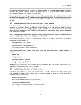
![AIGA 056/08
______________________________________________________________________
50
14 Product handling equipment
The hazards associated with product handling equipment depend on the properties of the products and the
conditions under which they must be handled. Each system shall be suitable for the temperatures, pressures,
and fluids involved.
14.1 Liquid storage
Because of the very low temperature of this service, cryogenic tanks require special design and insulation
techniques. These systems shall be designed and fabricated only by manufacturers knowledgeable in this
technology, the applicable codes, and the industry's experience to ensure their safety and integrity. See
CGA P-25, Guide for Flat-Bottomed LOX/LIN/LAR Storage Tank Systems, and API 620, Design and
Construction of Large, Welded, Low-Pressure Storage Tanks [68, 69].
Cryogenic tanks are generally constructed with the inner tank made of material suitable for cryogenic
temperatures and the outer tank of carbon steel. The annular space between these two vessels is filled with
insulation to minimize heat leak and boil off of the cryogenic fluid.
The two types of cryogenic tanks used most are:
– LP flat-bottomed tanks or spheres with the annular space filled with insulation and purged with dry
nitrogen. This type of tank design is generally used for large, field-erected storage tanks in stationary
service; and
– Vacuum-insulated tanks with powder/vacuum or superinsulation/vacuum in the annular space. This type of
tank design is generally shop fabricated and operated at either medium or high pressures.
Hazards associated with the operation of cryogenic liquid storage vessels include:
– cryogenic liquid leaks within the annular space;
– loss of vacuum in the annular space (vacuum-insulated tank only);
– loss of purge gas to the annular space (flat-bottomed tank only);
– overfilling the inner tank;
– overpressurization of the inner tank;
– overpressurization of the annular space;
– creation of vacuum in the inner tank;
– creation of vacuum in the annular space (flat-bottomed tank only);
– liquid spill and vapour cloud formation; and
– mechanical stresses caused by rapid cooldown.
These hazards and their mitigation are described for flat-bottomed tanks in CGA P-25 [68]. Although CGA P-25
was written to describe flat-bottomed tanks, it is generally applicable to vacuum-insulated tanks as well [68].
Other information on vacuum-insulated tanks is contained in CGA P-12; CGA P-40, Calculation Method for the
Analysis and Prevention of Overpressure During Refilling of Cryogenic Storage Tanks; and CGA PS-8, CGA
Position Statement on the Protection of Cryogenic Storage Tanks from Overpressure During Operator-
Attended Refill [7, 70, 71].
Most plants are provided with loading and/or unloading facilities for transferring liquid to or from tankers or
railroad tank cars. See CGA P-31, as well as AIGA 040/06, Good practices guide for loading and unloading of
cryogenic liquid tankers and CGA P-35, Guidelines for Unloading Tankers of Cryogenic Oxygen, Nitrogen, and
Argon [57, 67,72].](https://image.slidesharecdn.com/aiga05608safepracticesguideforcryogenicairseparationplants-160603134600/85/Aiga-safe-practices-guide-for-cryogenic-air-separation-plants-56-320.jpg)
![AIGA 056/08
______________________________________________________________________
51
Special precautions should be taken to prevent overpressurizing cryogenic transport vessels. See CGA PS-14,
CGA Position Statement on the Protection of Cryogenic Transport Vessels from Overpressurization During
Operator-Attended Refill, for overpressurization protection [73].
14.2 High pressure gas storage vessels
Due to their application, vessels used for HP gas storage are subject to cyclic stresses. They should be
designed, constructed, and inspected in accordance with applicable codes. These vessels are often located in
corrosive environments and should be periodically inspected for external corrosion.
HP gas storage vessels are sometimes relocated from one site to another. When this occurs, the design and
operating history should be investigated to ensure that the vessels are suitable for the desired application.
Relocated vessels should be carefully inspected and cleaned for the applicable service before being placed
back in operation.
Vessels should be protected by PRDs to limit overpressure due to external heat sources as specified in
CGA S-1.3, Pressure Relief Device Standards−Part 3−Stationary Storage Containers for Compressed
Gases [74].
Gas flowing from HP storage to a LP pipeline can result in a significant temperature drop due to Joule-
Thompson (JT) cooling. Care shall be exercised to ensure that downstream piping does not reach
embrittlement temperature.
14.3 Liquid vaporizers
The following hazards are specific to liquid vaporizers:
– If the vaporizer is blocked in while containing liquid and the heat input is maintained, a significant and rapid
pressure increase can occur. Appropriately sized pressure relief valves shall be installed;
WARNING: Overpressurization caused by trapped cryogenic liquid could rupture the piping, resulting in
personnel injury or equipment damage. Special care should be taken to ensure that PRDs are installed
between two valves, including check valves, to relieve pressure caused by trapped cryogenic liquids.
– When boiling oxygen, hydrocarbons can accumulate. Accumulation can be avoided by proper piping
design or periodic warming to ambient temperatures; and
– If the heat source of the vaporizer is lost or if the vaporizer flow capacity is exceeded, the outlet
temperature of the vaporizer can become very cold, potentially damaging downstream equipment and
piping. For hazard abatement, see 15.7.
WARNING: Carbon steel embrittlement by cold temperatures could rupture piping, resulting in personnel
injury or equipment damage. Special care should be taken to ensure that embrittlement does not occur.
15 Plant piping
15.1 General design considerations for plant piping
Plant piping systems shall be suitable for the temperatures, pressures, and cleanliness level for the fluids
involved. Design shall consider ASME B31.3, Code for Chemical Plants and Petroleum Refinery Piping, as well
as other national codes and ordinances [75].
Materials of construction shall be compatible with the intended service (see 6.3).
15.2 General design considerations for check valves
During the plant design, the consequence(s) of reverse flow through a check valve failure should be
determined. Potential hazardous consequences can include but are not necessarily limited to
overpressurization, purity excursions, or temperature excursions. If the consequence of failure presents a](https://image.slidesharecdn.com/aiga05608safepracticesguideforcryogenicairseparationplants-160603134600/85/Aiga-safe-practices-guide-for-cryogenic-air-separation-plants-57-320.jpg)
![AIGA 056/08
______________________________________________________________________
52
significant hazard and the hazard analysis uses the check valve to provide a layer of protection, then a
mechanical integrity program should be implemented. This program ensures that the check valve maintains its
capability to operate properly. The program may include periodic inspection and/or testing. The inspection
and/or test interval varies depending upon the check valve service and the consequences of failure.
15.3 Oxygen piping hazards
There are certain hazards associated with an oxygen piping system. For information on the unique design and
operating requirements of an oxygen piping system, see 6.3, 15.9.2, ASTM G-88, and AIGA 021/05 [28, 50].
15.4 Pressure relief devices
15.4.1 General considerations for pressure relief devices
Chemical processing plants require PRDs. Requirements for these devices are covered in other documents
such as ASME PTC 25-2001-2002, Pressure Relief Devices; API RP 520, Sizing, Selection and Installation of
Pressure-relieving Devices in Refineries, Part I–Sizing and Selection; API RP 520, Sizing, Selection, and
Installation of Pressure-relieving Devices in Refineries, Part II–Installation; and API RP 521, Guide for
Pressure-relieving and Depressurizing Systems (ANSI/API 521-1997) [76, 77, 78, 79].
Good practices include but are not limited to the following:
– venting PRDs away from work areas or other equipment;
– providing support to counterreactive forces when a device operates;
– sizing inlet and outlet piping so that pressure drop does not exceed code limits;
– protecting PRD discharge ports from weather;
– ensuring that bonnet vents are unrestricted; and
– conducting periodic testing using dry, oil-free air or nitrogen.
15.4.2 Design considerations for ASU pressure relief devices
A properly sized PRD is required to prevent overpressurization due to volume increase of vaporized cryogenic
fluids. At times a relief device can be quite large depending on the amount of liquid that can be trapped in the
system and how fast the heat is transferred into the cryogenic liquid. Causes of overpressurization include:
− loss of vacuum insulation;
− process upset conditions;
− ambient heat leak;
− high heat input to blocked-in process equipment and vaporizers;
− introduction of warm gas into cold process equipment;
− rapid vaporization of cryogenic fluids when introduced into warm equipment; or
− trapping cryogenic fluids between two valves.
WARNING: Overpressurization caused by trapped cryogenic liquid could rupture the piping, resulting in
personnel injury or equipment damage. Special care should be taken to ensure that PRDs are installed
between two valves including check valves to relieve pressure caused by trapped cryogenic liquids.
Compatible materials shall be used for systems containing oxygen.](https://image.slidesharecdn.com/aiga05608safepracticesguideforcryogenicairseparationplants-160603134600/85/Aiga-safe-practices-guide-for-cryogenic-air-separation-plants-58-320.jpg)
![AIGA 056/08
______________________________________________________________________
53
Discharge of PRDs for oxygen and flammable fluids shall be piped outdoors to a safe location. For systems in
an enclosed space, inert fluid vents shall be piped outdoors to a safe location if the vented volume lowers the
oxygen content of the enclosed space to a hazardous level.
Pressure relief valves should be located so their discharge cannot impinge on personnel or other equipment.
They should not discharge into working or operating areas frequented by plant personnel.
Vents shall be designed to disperse the vented fluid to prevent the formation of an oxygen-enriched, oxygen-
deficient, flammable, or cold atmosphere, which could harm personnel or damage equipment.
The design of the PRD and piping should consider the possibility of cryogenic temperatures resulting from PRD
operation. Vents shall be directed to prevent cryogenic liquid or gas from impinging on and cracking
surrounding carbon steel piping or equipment.
All PRDs in cryogenic service should be inspected periodically for ice accumulation. Accumulated ice should be
removed promptly. Failure to do so can prevent the PRD from operating properly.
15.5 Cryogenic piping
Any piping connection between a cryogenic liquid line and a warm piping element that is not normally flowing
shall be trapped to produce a gas seal, which prevents dead end boiling and cold migration. Typical examples
include:
– derime valves;
– liquid drains;
– PRDs;
– instrumentation sensing lines;
– vaporizer and pump inlets; and
– batch sample lines.
The gas seal separates cryogenic liquid from the warm piping element. The piping connected to the cryogenic
line should have sufficient vertical rise to generate a gas seal. For piping connections located inside the
coldbox, specially designed piping loops allow the production of a gas seal and prevent the accumulation of
liquid in the downstream piping. The vertical rise can be anywhere within the piping run to produce the gas
seal.
Any large bore piping in the coldbox that has a low point should have a drain line.
Many parts of the ASU process do not encounter oxygen-enriched fluids during normal operation. However,
they can be exposed to oxygen during process upsets, startup, and shutdown. It is common practice to clean
all cryogenic piping and equipment for oxygen service.
15.6 Dead legs
Vessels, process vaporizers, cryogenic pumps, drains, or piping containing oxygen-rich liquid should be
designed without dead legs. Dead legs can lead to dry boiling and hydrocarbon buildup in the remaining
oxygen-rich liquid. Where dead legs cannot be avoided by design, a continuous purge or periodic drain should
be provided.
15.7 Carbon steel piping
Carbon steel piping can be damaged by exposure to low temperature (–20 °F [–29 °C]) resulting from a plant
upset or a liquid vaporizer system failure. A temperature instrumented system shall be provided to remove the
low temperature source, for example, by closing isolation valves or stopping pumps (see 12.16.3). Piping from](https://image.slidesharecdn.com/aiga05608safepracticesguideforcryogenicairseparationplants-160603134600/85/Aiga-safe-practices-guide-for-cryogenic-air-separation-plants-59-320.jpg)
![AIGA 056/08
______________________________________________________________________
55
– Drain liquids as required and ensure that the product disposal systems are operating properly; and
– Secure cryogenic and prepurification adsorbers.
16.1 Coldbox shutdown
Depending on the type of plant, the reason for the shutdown, and the expected length of the shutdown,
additional safety procedures can be required by the manufacturer’s instructions. Further recommendations are
given in 12.16 and AIGA 035/06 [38].
For cryogenic adsorbers, a significant increase in stream temperature can cause sudden desorption of the
contaminants, releasing them into downstream equipment. This can be a significant safety hazard; therefore,
cryogenic adsorbers shall either be kept at operating temperatures or regenerated during a shutdown.
When shutdown conditions allow, the offline vessel of the PPU shall be completely regenerated before securing
the PPU. This allows a properly regenerated bed to be placed on stream at the subsequent plant startup.
16.2 Liquid and gas disposal
Liquid from an air separation plant shall not be drained onto the plant floor or ground, but shall be piped to an
appropriate disposal system. Typical disposal systems are:
– liquid spray header in the cooling tower fan discharge;
– dump tanks with a suitable vaporizing system;
– heat exchangers; and
– fan vaporizer.
Oxygen-rich liquid should not be piped to cooling tower fan systems.
Liquid disposal and derime vent gas piping configurations require attention to avoid any possible contact in the
disposal of oxygen-rich liquid and derime gas that can contain high quantities of hydrocarbons, especially
acetylene. Any derime outlets that can contain oil such as air from exchangers where lubricated compressors
are used shall have separate vent systems.
A disposal piping system may separate the inert and oxygen-rich liquids to prevent possible cross
contamination of ASU products. Liquid disposal systems should have a low point drain to avoid accumulation of
hydrocarbons.
Manually operated drain and vent valves shall be monitored locally while they are open so that corrective action
can be taken as required.
Any large gaseous oxygen or nitrogen vents should be conducted outside and preferably directed upwards.
When vents are outside, high concentrations of oxygen or nitrogen in confined areas, work areas, or adjacent
to intake ducts shall be avoided.
Dumping or vaporizing cryogenic liquids can create a dense fog, even in low humidity conditions. This can
create a hazardous situation by greatly reducing visibility. Special care should be taken to ensure that roads
and traffic are not affected by these types of fogs.
16.3 Plant derime
Derime is often necessary to remove accumulated contaminants from various sections of the coldbox. Details
of derime procedures are given by the manufacturer. An overview of derime procedures is given in
AIGA 035/06 [38].
Shutdown for periodic deriming is usually combined with maintenance checks, repairs, or modifications. It is
good practice to accomplish a partial derime to get the plant reasonably warm, perform the maintenance, and](https://image.slidesharecdn.com/aiga05608safepracticesguideforcryogenicairseparationplants-160603134600/85/Aiga-safe-practices-guide-for-cryogenic-air-separation-plants-61-320.jpg)
![AIGA 056/08
______________________________________________________________________
57
– Trapped or elevated pressure, cryogenic liquids, and the coldbox insulation shall be considered and dealt
with.
Prerequisites to any work within the coldbox should be completed such as:
– draining of all liquids;
– deriming;
– positively isolating product liquid and gas lines with double block and bleed valving or blinding of flanges;
– positively isolating the casing purge gas with double block and bleed valving or blinding of flanges;
– depressurizing; and
– purging with air followed by atmosphere monitoring.
In rare instances, entry into the coldbox without complete warming is unavoidable. This is an extremely
hazardous activity. Careful and complete consideration shall be given to the extra hazards of the coldbox
environment such as limited visibility, cryogenic temperatures, and oxygen-enriched or oxygen-deficient
atmospheres.
Part or all of the coldbox insulation shall be removed before the start of any work within the casing. The extent
of insulation removal depends on the type of insulation used in the coldbox and the location of the equipment to
be worked on. Coldboxes insulated with powdered insulation such as perlite, vermiculite, and microcel should
be completely emptied. Refer to AIGA 032/08 for guidance on the safe handling of powder-insulated
coldboxes [59].
Coldboxes insulated with wool-type insulation can be entered for local repairs by tunneling through the wool
after thorough purging of insulation space with air. These tunnels shall be adequately shored to guard against
insulation collapse and positively ventilated with fresh air. Personnel handling the rock wool should always
wear appropriate protective clothing, gloves, and goggles to avoid skin and eye irritation. This insulation also
should be checked periodically for moisture. If moist, it should be discarded and replaced with fresh rock wool.
Such work within a mineral wool-insulated enclosure is a confined space entry and should be performed as
described in 17.5.
17.5 Hazards of working in oxygen-enriched or oxygen-deficient atmospheres
Strict precautions shall be taken before entering any confined spaces such as coldbox casings, vessels,
storage tanks, ducts, or other closed or poorly ventilated areas with potentially oxygen-enriched or oxygen-
deficient atmospheres, as serious injuries or fatalities can occur. Atmospheres within all such confined spaces
shall be checked and unprotected personnel prohibited from entering an atmosphere that does not fall within
the range of 19.5% to 23.5% oxygen. See AIGA 008/04, AIGA 005/04 and also CGA P-12, 29 CFR 1910.146,
CGA SB-2, CGA SB-15, and CGA P-39 for further guidance [7, 8, 9, 10, 15].
DANGER: Entering an area with an oxygen-enriched or oxygen-deficient atmosphere without following proper
procedures will result in serious injury or death.
17.6 Cleaning
Oxygen cleaning has special requirements. All equipment, piping, and vessels that are replaced or repaired
shall be suitably cleaned before being returned to service. All replacement parts shall be oxygen compatible
and shall be cleaned for oxygen service. All tools used to remove and replace components shall be cleaned for
oxygen service (see AIGA 012/04 , CGA G-4.1and ASTM G93) [29, 30, 31].
Many parts of the ASU process do not encounter oxygen-enriched fluids during normal operation. However,
they can be exposed to oxygen during process upsets, startup, and shutdown. It is common practice to clean
all cryogenic equipment for oxygen service.](https://image.slidesharecdn.com/aiga05608safepracticesguideforcryogenicairseparationplants-160603134600/85/Aiga-safe-practices-guide-for-cryogenic-air-separation-plants-63-320.jpg)
![AIGA 056/08
______________________________________________________________________
58
18 Operations and training
18.1 Operating procedures
The air separation plant including all of the machinery components should be operated and maintained in
accordance with operating instructions furnished by the manufacturers. These instructions shall be
incorporated into plant operating and maintenance procedures.
Plant personnel shall be trained in operating and maintenance procedures.
18.2 Emergency procedures
Procedures should be developed to cover the proper response to anticipated emergency conditions for which
the plant operators may have to contend. Potential emergency conditions should include plant upset conditions,
mechanical malfunctions, and power failures, as well as environmental and civil disturbances that can affect
plant safety. Emergency conditions that should be considered are:
– energy release;
– cryogenic liquid spill;
– fog cloud from a cryogenic release;
– site security threat (see AIGA 003/07 Site Security) [80];
– severe weather conditions such as typhoon, tornado, or flood; and
– adjacent industry incidents such as explosions, toxic chemical releases, or toxic gas releases.
18.3 Management of change
MOC is the procedure used to ensure that changes are implemented correctly and safely and are documented.
These documents shall be maintained at the plant. Any proposed change to equipment, controls, software,
procedures, and facilities shall require a documented review by technically competent personnel and
authorization by the appropriate personnel before implementation. This review and authorization shall apply to
all proposed modifications or changes whether they are permanent, temporary, or emergency in nature. All
appropriate plant documentation such as a process and instrument diagram, equipment specifications and
drawings, and operating and maintenance procedures shall be updated.
Changes that should fall under MOC include:
– changing control systems;
– bypassing of safety systems;
– changing procedures or operating instructions;
– operating outside of approved limits;
– changing process technology such as rates or raw materials;
– changing equipment or materials of construction;
– changing equipment specifications; or
– modifying computer programs.
Replacement-in-kind is an exact replacement or design alternative that meets all design specifications of the
item being replaced. Replacement-in-kind does not require MOC approval (see AIGA 010/04, Management of
Change) [81].](https://image.slidesharecdn.com/aiga05608safepracticesguideforcryogenicairseparationplants-160603134600/85/Aiga-safe-practices-guide-for-cryogenic-air-separation-plants-64-320.jpg)
![AIGA 056/08
______________________________________________________________________
59
19 References
Unless otherwise specified, the latest edition shall apply.
[1] Schmidt, William, K. Winegardner, M. Dennehy, and H. Castle-Smith, “Safe Design and Operation of a
Cryogenic Air Separation Unit,” Process Safety Progress, Dec 2001, Vol. 20, No.4, pp. 269-279.
[2] AIGA 057/08 Safe Use of Brazed Aluminium Heat Exchangers for Producing Pressurized Oxygen, Asia
Industrial Gases Association. www.asiaiga.org
[3] IEC 61511, Functional Safety–Safety Instrumented Systems for the Process Industry Sector—Part 1:
Framework, Definitions, System, Hardware and Software Requirements, International Electrotechnical
Commission, 3, rue de Varembé, P.O. Box 131, CH-1211 Geneva 20, Switzerland. www.iec.ch
[4] United States Pharmacopoeia and National Formulary, U.S. Pharmacopoeia, 12601 Twinbrook Pkwy.,
Rockville, MD 20850. www.usp.org
[5] CGA G-10.1, Commodity Specification for Nitrogen, Compressed Gas Association, Inc., 4221 Walney Rd.,
5th Floor, Chantilly, VA 20151. www.cganet.com
[6] CGA G-4.3, Commodity Specification for Oxygen, Compressed Gas Association, Inc., 4221 Walney Rd., 5th
Floor, Chantilly, VA 20151. www.cganet.com
[7] CGA P-12, Safe Handling of Cryogenic Liquids, Compressed Gas Association, Inc., 4221 Walney Rd., 5th
Floor, Chantilly, VA 20151. www.cganet.com
[8] Code of Federal Regulations, Title 29 CFR (Labor), Superintendent of Documents, U.S. Government
Printing Office, Washington, DC 20402. www.gpoaccess.gov
[9] CGA SB-2, Oxygen-Deficient Atmospheres, Compressed Gas Association, Inc., 4221 Walney Rd., 5th
Floor, Chantilly, VA 20151. www.cganet.com
[10] AIGA 008/04 Hazards of Inert Gases , Asia Industrial Gases Association, www.asiaiga.org
[11] CSB Safety Bulletin, Hazards of Nitrogen Asphyxiation, U.S. Chemical Safety and Hazard Investigation
Board, 2175 K Street NW, Suite 400, Washington, DC 20037. www.csb.gov
[12] CSB Brochure, Nitrogen-Enriched Atmospheres Can Kill, U.S. Chemical Safety and Hazard Investigation
Board, 2175 K Street NW, Suite 400, Washington, DC 20037. www.csb.gov
[13] CSB PowerPoint Presentation, The Hazards of Nitrogen Asphyxiation, U.S. Chemical Safety and Hazard
Investigation Board, 2175 K Street NW, Suite 400, Washington, DC 20037. www.csb.gov
[14] ANSI Z88.2, Respiratory Protection, American National Standards Institute, 25 W. 43rd St., 4th Floor, New
York, NY 10036. www.ansi.org
[15] AIGA 005/04 Fire Hazards of Oxygen & Oxygen Enriched Atmospheres, Asia Industrial Gases Association
www.asiaiga.org
[16] ASTM G63, Standard Guide for Evaluating Nonmetallic Materials for Oxygen Service, ASTM International,
100 Bar Harbor Dr., West Conshohocken, PA 19428. www.astm.org
[17] ASTM G94, Standard Guide for Evaluating Metals for Oxygen Service, ASTM International, 100 Bar
Harbor Dr., West Conshohocken, PA 19428. www.astm.org
[18] ASTM A312, Standard Specification for Seamless, Welded, and Heavily Cold Worked Austenitic Stainless
Steel Pipe, ASTM International, 100 Bar Harbor Dr., West Conshohocken, PA 19428. www.astm.org](https://image.slidesharecdn.com/aiga05608safepracticesguideforcryogenicairseparationplants-160603134600/85/Aiga-safe-practices-guide-for-cryogenic-air-separation-plants-65-320.jpg)
![AIGA 056/08
______________________________________________________________________
60
[19] ASTM B241, Standard Specification for Aluminium and Aluminium-Alloy Seamless Pipe and Seamless
Extruded Tube, ASTM International, 100 Bar Harbor Dr., West Conshohocken, PA 19428. www.astm.org
[20] ASTM B209, Standard Specification for Aluminium and Aluminium-Alloy Sheet and Plate, ASTM
International, 100 Bar Harbor Dr., West Conshohocken, PA 19428. www.astm.org
[21] ASTM B75, Standard Specification for Seamless Copper Tube, ASTM International, 100 Bar Harbor Dr.,
West Conshohocken, PA 19428. www.astm.org
[22] ASTM B88, Standard Specifications for Seamless Copper Water Tube, ASTM International, 100 Bar
Harbor Dr., West Conshohocken, PA 19428. www.astm.org
[23] ASTM B165 VNS 4400, Standard Specification for Nickel-Copper Alloy (UNSN0400)* Seamless Pipe and
Tube, ASTM International, 100 Bar Harbor Dr., West Conshohocken, PA 19428. www.astm.org
[24] ASTM B127, Standard Specifications for Nickel-Copper Alloy (UNS 04400) Plate,Sheet, and Strip, ASTM
International, 100 Bar Harbor Dr., West Conshohocken, PA 19428. www.astm.org
[25] ASTM B43, Standard Specification for Seamless Red Brass Pipe, Standard Sizes, ASTM International,
100 Bar Harbor Dr., West Conshohocken, PA 19428. www.astm.org
[26] ASTM A53, Standard Specification for Pipe, Steel, Black and Hot-Dipped, Zinc-Coated Welded and
Seamless, ASTM International, 100 Bar Harbor Dr., West Conshohocken, PA 19428. www.astm.org
[27] ASTM Al06 Grade B, Standard Specification for Seamless Carbon Steel Pipe for High Temperature
Service, ASTM International, 100 Bar Harbor Dr., West Conshohocken, PA 19428. www.astm.org
[28] ASTM G88, Standard Guide for Designing Systems for Oxygen Service, ASTM International, 100 Bar
Harbor Dr., West Conshohocken, PA 19428. www.astm.org
[29] CGA G-4.1, Cleaning Equipment for Oxygen Service, Compressed Gas Association, Inc., 4221 Walney
Rd., 5th Floor, Chantilly, VA 20151. www.cganet.com
[30] ASTM G93, Standard Practice for Cleaning Methods and Cleanliness Levels for Material and Equipment
Used in Oxygen-Enriched Environments, ASTM International, 100 Bar Harbor Dr., West Conshohocken, PA
19428. www.astm.org
[31] AIGA 012/04 Cleaning of Equipment for Oxygen Service, Asia Industrial Gases Association,
www.asiaiga.org
[32] NFPA 70, National Electrical Code®
, National Fire Protection Association, 1 Batterymarch Park, Quincy,
MA 02269. www.nfpa.org
[33] ANSI S12.3, Statistical Methods for Determining and Verifying Stated Noise Emission Values of Machinery
and Equipment, American National Standards Institute, 25 West 43rd St., New York, NY 10036. www.ansi.org
[34] ANSI S12.5, Requirements for Performance and Calibration of Reference Sound Sources, American
National Standards Institute, 25 West 43rd St., New York, NY 10036. www.ansi.org
[35] ANSI S12.7, Methods for Measurement of Impulse Noise, American National Standards Institute, 25 West
43rd St., New York, NY 10036. www.ansi.org
[36] ANSI S12.9-1988 (R 2003), Quantities and Procedures for Description and Measurement of Environmental
Sound, Part 1, American National Standards Institute, 25 West 43rd St., New York, NY 10036. www.ansi.org
[37] ASME PTC 36, Measurement of Industrial Sound, ASME International, Three Park Ave., New York, NY
10016. www.asme.org](https://image.slidesharecdn.com/aiga05608safepracticesguideforcryogenicairseparationplants-160603134600/85/Aiga-safe-practices-guide-for-cryogenic-air-separation-plants-66-320.jpg)
![AIGA 056/08
______________________________________________________________________
61
[38] AIGA 035/06 Safe Operation of Reboilers/Condensers in Air Separation Units (CGA P-8.4), Asia Industrial
Gases Association, www.asiaiga.org
[39] McKinley, C. and F. Himmelberger, “The Role of Contaminants in Formulating Oxygen Plant Safety
Principles,” Chemical Engineering Progress, March 1957, Vol. 53, No. 3, pp. 112-121. www.aiche.org
[40] Bohlken, S.F., “Heat Exchanger Explosion in a Nitrogen-Wash Unit,” Chemical Engineering Progress, Vol.
57, No. 4 (April 1961), pp. 49-52. www.aiche.org
[41] Sakai, Y., “This Ammonia Unit Exploded,” Petroleum Refiner, Vol. 40, No. 1 (January 1961), pp. 178-181.
www.gulfpub.com
[42] Haseba, S., T. Shimose, N. Kubo, T. Kitagawa, “Nitric Oxide Explosion,” Chemical Engineering Progress,
Vol. 62, No. 4 (April 1966), pp. 92-96. www.aiche.org
[43] Wenning, U., “Nitrous Oxide in Air Separation Plants,” Reports on Science and Technology, No. 60 (1998),
Linde AG, Abraham-Lincoln-Strasse 21, 65189 Wiesbaden, Germany. www.linde.com
[44] Hardeveld, R.M., M.J. Groeneveld, J.-Y. Lehman, and D.C. Bull, “Investigation of an Air Separation Unit
Explosion,” Journal of Loss Prevention in the Process Industries, 14 (2001), pp. 167-180, Elsevier, 6277 Sea
Harbor Dr., Orlando, FL 32887. www.elsevier.com
[45] Meilinger, M., “Promoted Ignition-Combustion Tests with Structured Aluminium Packings in Gaseous
Oxygen with Argon or Nitrogen Dilution at 0.1 and 0.6 mPa,” Flammability and Sensitivity of Materials in
Oxygen-Enriched Atmospheres: Tenth Volume, ASTM STP 1454, pp. 137-150, ASTM International, 100 Bar
Harbor Dr., West Conshohocken, PA 19428. www.astm.org
[46] ASME B19.1, Safety Standard for Air Compressor Systems, American Society of Mechanical Engineers,
Three Park Ave., New York, NY 10016. www.asme.org
[47] ASME B19.3, Safety Standard for Compressors for Process Industries, American Society of Mechanical
Engineers, Three Park Ave., New York, NY 10016. www.asme.org
[48] Standards of the Tubular Exchanger Manufacturers' Association, Tubular Exchanger Manufacturers'
Association, 25 N. Broadway, Tarrytown, NY 10591. www.tema.org
[49] ASME Boiler and Pressure Vessel Code, Section VIII, Div 1, American Society of Mechanical Engineers,
Three Park Ave., New York, NY 10016. www.asme.org
[50] AIGA 021/05 Oxygen Pipeline Systems (CGA G4.4), Asia Industrial Gases Association, www.asiaiga.org
[51] CGA G-4.6, Oxygen Compressor Installation and Operation Guide, Compressed Gas Association, Inc.,
4221 Walney Rd., 5th Floor, Chantilly, VA 20151. www.cganet.com
[52] EIGA Doc. 27/ 01, Centrifugal compressors for oxygen service, Industrial Gas Committee, Avenue des
Arts 3-5, B 1210 Brussels, Belgium. www.eiga.eu
[53] AIGA 048/08, Reciprocating compressors for oxygen service, Asia Industrial Gases Association,
www.asiaiga.org
[54] W. Schmidt, K. Kovak, W. Licht, and S. Feldman, “Managing Trace Contaminants in Cryogenic Air
Separation,” AIChE Spring Meeting, Atlanta, GA, March 5-9, 2000. www.aiche.org
[55] Montreal Protocol on Substances that Deplete the Ozone Layer, United Nations Environment Programme,
Ozone Secretariat, P.O. Box 30552, Nairobi, Kenya. www.unep.org/ozone
[56] AIGA 055/08 Installation Guide for Stationary, Electric-Motor-Driven, Centrifugal Liquid Oxygen Pumps,
Asia Industrial Gases Association, www.asiaiga.org](https://image.slidesharecdn.com/aiga05608safepracticesguideforcryogenicairseparationplants-160603134600/85/Aiga-safe-practices-guide-for-cryogenic-air-separation-plants-67-320.jpg)
![AIGA 056/08
______________________________________________________________________
62
[57] CGA P-31, Liquid Oxygen, Nitrogen, and Argon Cryogenic Tanker Loading System Guide, Compressed
Gas Association, Inc., 4221 Walney Rd., 5th Floor, Chantilly, VA 20151. www.cganet.com
[58] CGA G-4.8, Safe Use of Aluminium-Structured Packing for Oxygen Distillation (EIGA Doc. 701/04),
Compressed Gas Association, Inc., 4221 Walney Rd., 5th Floor, Chantilly, VA 20151. www.cganet.com
[59] AIGA 032/08, Perlite Management , Asia Industrial Gases Association , www.asiaiga.org
[60] AIGA 035/06, Safe operation of reboilers/condensers in air separation units, Asia Industrial Gases
Association, www.asiaiga.org
[61] Miller, E., S. Auvil, N. Giles, and G. Wilson, “The Solubility of Nitrous Oxide as a Pure Solute and in
Mixtures with Carbon Dioxide in Air Separation,” AIChE Spring Meeting, Atlanta, GA, March 5-9, 2000,
American Institute of Chemical Engineers, 3 Park Ave., New York, NY 10016. www.aiche.org
[62] Meneses, D., J. Thonnelier, C. Szulman, and E. Werlen, “Trace Contaminant Behaviour in Air Separation
Units,” Cryogenics 2000 Conference, Prague, October 2000, International Institute of Refrigeration, 177,
boulevard Malesherbes, 75017 Paris, France. www.iifiir.org
[63] CGA G-5, Hydrogen, Compressed Gas Association, Inc., 4221 Walney Rd., 5th Floor, Chantilly, VA 20151.
www.cganet.com
[64] CGA G-5.4, Standard for Hydrogen Piping Systems at Consumer Locations, Compressed Gas
Association, Inc., 4221 Walney Rd., 5th Floor, Chantilly, VA 20151. www.cganet.com
[65] CGA G-5.5, Hydrogen Vent Systems, Compressed Gas Association, Inc., 4221 Walney Rd., 5th Floor,
Chantilly, VA 20151. www.cganet.com
[66] CGA P-28, Risk Management Plan Guidance Document for Bulk Liquid Hydrogen Systems, Compressed
Gas Association, Inc., 4221 Walney Rd., 5th Floor, Chantilly, VA 20151. www.cganet.com
[67] AIGA 040/06 Good practices guide for loading and unloading of cryogenic liquid tankers, Asia Industrial
Gases Association, www.asiaiga.org
[68] CGA P-25, Guide for Flat-Bottomed LOX/LIN/LAR Storage Tank Systems, Compressed Gas Association,
Inc., 4221 Walney Rd., 5th Floor, Chantilly, VA 20151. www.cganet.com
[69] API 620, Design and Construction of Large, Welded, Low-Pressure Storage Tanks, American Petroleum
Institute, 1220 L Street, NW, Washington, DC 20005. www.api.org
[70] CGA P-40, Calculation Method for the Analysis and Prevention of Overpressure During Refilling of
Cryogenic Storage Tanks, Compressed Gas Association, Inc., 4221 Walney Rd., 5th Floor, Chantilly, VA
20151. www.cganet.com
[71] CGA PS-8, CGA Position Statement on the Protection of Cryogenic Storage Tanks from Overpressure
During Operator-Attended Refill, Compressed Gas Association, Inc., 4221 Walney Rd., 5th Floor, Chantilly, VA
20151. www.cganet.com
[72] CGA P-35, Guidelines for Unloading Tankers of Cryogenic Oxygen, Nitrogen, and Argon, Compressed
Gas Association, Inc., 4221 Walney Rd., 5th Floor, Chantilly, VA 20151. www.cganet.com
[73] CGA PS-14, CGA Position Statement on the Protection of Cryogenic Transport Vessels from
Overpressurization During Operator-Attended Refill, Compressed Gas Association, Inc., 4221 Walney Rd., 5th
Floor, Chantilly, VA 20151. www.cganet.com
[74] CGA S-1.3, Pressure Relief Device Standards—Part 3—Stationary Storage Containers for Compressed
Gases, Compressed Gas Association, Inc., 4221 Walney Rd., 5th Floor, Chantilly, VA 20151. www.cganet.com](https://image.slidesharecdn.com/aiga05608safepracticesguideforcryogenicairseparationplants-160603134600/85/Aiga-safe-practices-guide-for-cryogenic-air-separation-plants-68-320.jpg)
![AIGA 056/08
______________________________________________________________________
63
[75] ASME B31.3, Process Piping, American Society of Mechanical Engineers, Three Park Ave., New York, NY
10016. www.asme.org
[76] ASME PTC 25-2001, Pressure Relief Devices, American Society of Mechanical Engineers, Three Park
Avenue, New York, NY 10016. www.asme.org.
[77] API RP 520, Sizing, Selection and Installation of Pressure-relieving Devices in Refineries, Part I—Sizing
and Selection, American Petroleum Institute, 1220 L Street NW, Washington, DC 20005. www.api.org
[78] API RP 520, Sizing, Selection, and Installation of Pressure-relieving Devices in Refineries, Part II—
Installation, American Petroleum Institute, 1220 L Street NW, Washington, DC 20005. www.api.org
[79] API RP 521, Guide for Pressure-relieving and Depressurizing Systems, American Petroleum Institute,
1220 L Street NW, Washington, DC 20005. www.api.org
[80] AIGA 003/07 Site Security, Asia Industrial Gases Association, www.asiaiga.org
[81] AIGA 010/04 Management of change, Asia Industrial Gases Association, www.asiaiga.org
[82] IGC 44/00, Campaign against Asphyxiation, European Industrial Gases Association, Avenue des Arts 3-5,
B 1210 Brussels, Belgium. www.eiga.eu
[83] EIGA NL 77/03, Asphyxiation fatalities on a construction site, Asphyxiation near miss accident in open air,
etc., European Industrial Gases Association, Avenue des Arts 3-5, B 1210 Brussels, Belgium. www.eiga.eu](https://image.slidesharecdn.com/aiga05608safepracticesguideforcryogenicairseparationplants-160603134600/85/Aiga-safe-practices-guide-for-cryogenic-air-separation-plants-69-320.jpg)


