Displacement mechanical amplifiers designed on poly-siliconIJECEIAES
Using Poly-Silicon, the implementation of novel Displacement-amplifying Compliant Mechanisms (DaCM), in two geometries of accelerometers, allows for remarkable improvements in their operation frequency and displacement sensitivity, with different proportions. Similar DaCM´s geometries were previously implemented by us with Silicon. In all mentioned cases, the geometries of DaCM´s are adjusted in order to use them with Conventional Capacitive Accelerometer (CCA) and Capacitive Accelerometer with Extended Beams (CAEB), which operate in-plane mode, (y-axis). It should be noted that CAEB shows improvements (95.33%) in displacement sensitivity compared to ACC. Simulations results, carried out using Ansys Workbench software, validate the system’s performance designed with Poly-Silicon. Finally, a comparison with the similar systems, previously designed with Silicon, is also carried out.
Copper Bulk General (Cu) was chosen for the pivot material on its merits of possessing good
electrical conductivity and optimised flexibility and stiffness for elastic recovery.
The simulation, using Intellisuite, attained a working switch design, with an ‘Air-Gap’ of
1µm between the contacts, thus providing isolation when the switch is open-circuited.
The energy sector is moving into the era of distributed generation (DG) and microgrids
(MGs). The stability and operation aspects of converter-dominated DG MGs, however, are faced by
many challenges. To overcome these difficulties, this paper presents a new large-signal-based control
topology for DG power converters that is suitable for both grid connected and islanding modes of
operation without any need to reconfigure the control system and without islanding detection. To
improve MG stability and to guarantee stability and high performance of the MG system during sudden
harsh transients such as islanding, grid reconnection, and large load power changes, a nonlinear MG
stabilizer is proposed. We propose a novel control topology for microgrids which can work in both grid
connected and islanding modes without reconfiguration so it does not require islanding detection
technique, the controller is based on the concept of synchronverter In this paper, a radical step is taken
to improve the synchronverter as a self-synchronized synchronverter by removing the dedicated
synchronization unit
A Study of Shading Effect on Photovoltaic Modules with Proposed P&O Checking ...Yayah Zakaria
Sun irradiation levels and associated temperature changes are the main factors that influence the conversion of solar energy into electricity. Most energy is produced during a hot sunny day as the sun irradiation is at the maximum level and uniform throughout the solar photovoltaic (PV). However, most solar PV were frequently get shadowed, completely or partially, by the neighbouring buildings, trees and passing clouds. Consequently, the solar PV has lower voltage and current output, hence,
multiple maximum power points (MPP) are existed on the PV curve, which could cause confusion to the conventional Maximum Power Point Tracker (MPPT) to track the true MPP for the PV system. Thus, it is important to examine the impacts of partial shading on the solar PV in order to extract the maximum possible power. This paper presents a MATLAB-based modelling for simulation and experimental setup to study the I-V and P-V characteristics of a solar module under a non-uniform irradiation due to partial shading condition (PSC). Furthermore, this study is also proposed an effective method (a variable step size of P&O with checking algorithm) that is low cost and higher tracking efficiency. Thus, this study is essential in improving and evaluating any new MPPT algorithm under the PSC.
Results of a series of tests designed by the National Renewable Energy Laboratory (NREL) and conducted by PV Evolution Labs (PVEL) to measure the performance of various inverter technologies in various shading conditions were published today. The test determined the annual percentage of energy recovered by power optimizers and micro inverters when compared to traditional string inverter systems in shaded conditions.The results indicate that the SolarEdge optimized system generates 2%, 5% and over 8% more energy than traditional string inverters in light, medium and heavy shading scenarios, respectively.The SolarEdge system outperformed all systems in annual energy production demonstrating higher results than the leading micro inverter solution as well.
"The SolarEdge system yielded more energy than the string inverter system in all tests. On an annual average, the SolarEdge system recovered 24.8% of energy lost due to shading, while the microinverter system recovered 23.2%," says Matt Donovan, PV Evolution Labs.
Simulation and Modeling of Silicon Based Single Electron TransistorIJECEIAES
In this work, we simulated and modeled silicon quantum dot based single electron transistor (SET). We simulated the device using non-equilibrium Green’s function (NEGF) formalism in transport direction coupled with Schrodinger equation in transverse directions. The characteristics of SET such as Coulomb blockade and Coulomb diamonds were observed. We also present a new efficient model to calculate the current voltage (IV) characteristics of the SET. The IV characteristic achieved from the model are very similar to those from simulations both in shape and magnitude. The proposed model is capable of reproducing the Coulomb diamond diagram in good agreement with the simulations. The model, which is based on transmission spectrum, is simple, efficient and provides insights on the physics of the device. The transmission spectrum at equilibrium is achieved from simulations and given as input to the model. The model then calculates the evolved transmission spectra at non-equilibrium conditions and evaluates the current using Landauers formula.
Photovoltaic (PV) is one of the most important sources of renewable energy in the world. Its current efficiency could be increased up to 60% by using dual axes solar tracker, which maximise PV exposure to sun. The most important component in dual axes solar tracker is sensing location of the sun. Four light dependent resistors (LDR) are used as the sensors, connected to potentiometers to increase their accuracy. Arduino UNO is used as the controller to control two stepper motors. Two experiments have been carried out, where the tolerance of the LDR has been found to be 0.05V and the calibration of the four LDRs to have the error of 0.03V. Both experiments proved the capability of LDR for dual axes solar tracker and potentiometer to increase their accuracy.
Zero point energy conversion for selfsustained generationMocLan2
In this paper zero point energy conversion is proposed for self-sustained generator applications. Our entire
universe balance is based on a magnetic energy lying in a minimum energy point called zero-point. By using an energy
conversion machine magneto-gravitic link can be made zero-point energy by taking kinetic energy form i.e. rotational
motion .Kinetic energy link is constructed using a special permanent magnet arrangement and it is independent of
electricity . It uses perpetual motion and the kinetic energy is later converted by using a special type low speed axial flux
alternator, comprising two rotating discs in-between which the coil is placed from which the power is drawn .
Fragments of Lecture 1 about Dresden Treasure Hunt
Фрагменты первая лекция из цикла об истории создания Дрезденских художественных коллекций и спасении их сокровищ в 1945 г,
PowerPoint presentations from Fundación Capital's South-South Knowledge Exchange Forum, organized with support from IFAD "Leveraging Opportunities to Encourage Financial Inclusion"
Resonance frequency analysis of laser optical fiber based on microcantileverIJECEIAES
The normal frequency of smart beams was originated utilizing FEM [Ansys and Comsol] code for first five modes by varying the position of actuator from the fixed end of the structure, and it has a suitable arrangement with analytically found the standard frequency. This paper includes learning a resonance frequency analysis of laser optical fiber based on microcantilever of designing magnetic actuator using Ansys and Comsol simulation. The design of optical fiber includes Nickel cantilever, two magnets and one coil that apply to force on the cantilever. After the current flows in the coil domain, the shape of microcantilever will be deformed. It will move to z- direction that depends on the force direction. Two methods including, Comsol Multiphysics, Ansys and analytical equations have been utilized to calculate the resonance frequency, current and force values. The simulation results include calculating the current (magnetic current density) and effects of the magnetic field of the coil on the cantilever (force calculation). Utilizing this method is to limit faults(errors) of optical fiber laser between transmitter and receiver system (detection system) for any time of cutting coil when the signal of a laser passes through the coil. In conculsions, resonant frequency (f_n) tuning using cantilivier presented in the resrach have larger variable range by using simulations. However,the adjusting of the system and changing the deminsions.Resolutions to this problematic contain tuning the modes of resonant frequency to produce by cantilivier with 2-magnets and coil when the signal pass from laser source. Based on these simulations and characterization results, the proposed assembly can be a good applicant for evolving a low price, high material platform for many biological, laser optical fiber, communication, machine learning, biosensors and biomedical applications.
solar power satellite & microwave power transmissionbhavisha patel
In this seminar topic,I included all the things related SPS system & how microwave power transmission can done through magetron,retro directive beam controlling scheme & all.I also mentioned the design of optical rectenna & economic evolution of the topic.
IJERA (International journal of Engineering Research and Applications) is International online, ... peer reviewed journal. For more detail or submit your article, please visit www.ijera.com
Single material construction of controllable micromirrors for directing light forces a choice between either high performance and limited movement transmission geometries, or lower performance and wider range of shapes.
We eliminate constraints by using separate MEMS and AM parts, allowing customization of mirror speed and range for different applications. 1mm hexagonal mirrors are single crystal silicon, while polymer transmission structures are 3D printed onto the mirror underside using projection microstereolithography. An electronic comb driven paddle on a PCB will form the base.
We built and tested a way to handle and place components.
Micromachined Electro-Mechanical Systems, also called microfabricated Systems, have evoked great interest in the scientific and engineering communities. This is primarily due to several substantive advantages that MEMS offer: orders of magnitude smaller size, better performance than other solutions, possibilities for batch fabrication and cost-effective integration with electronics, virtually zero dc power consumption and potentially large reduction in power consumption, etc.
This Seminar would give an introduction to these exciting developments and the technology and design approaches for the realization of these integrated systems. It would be followed with an introduction to the design of microsensors, such as the pressure sensor and the accelerometer, which began the MEMS revolution.
A systematic approach is developed to select manufacturing Process Chains for the generic elements of a MEMS device. A database of MEMS Process Chains and their attendant process attributes is developed from the existing literature, and used to construct Process Attribute charts. The performance requirements of MEMS beams and trenches are translated into the same set of Process Attributes. This allows for a screening of the Process Chains to obtain a list of candidate manufacturing methods.
I begin with a quick introduction to MEMS technology, micron scale and show that silicon is eminently suited for micromechanical devices and therefore the possibility of integrating MEMS with VLSI electronics. Smart cell phones and wireless enabled devices are poised to become commercial engines for the next generation of MEMS, since MEMS provide not only better functionality with smaller chip area, but also alternative transceiver architectures for improved functionality, performance and reliability.
The application domains cover microsensors and actuators for physical quantities, of which MEMS for automobile & consumer electronics forms a large segment; microfabricated subsystems for communications and computer systems.
Paul Ahern - Overview of Micro & Nano TransducersPaul Ahern
Abstract— The aim of this paper is to present a review of current transducer technology, fabrication methods and materials pertinent to the nanotechnology and MEMS era. We begin with an introduction to the concept of a transducer and the historical context, and then review some specific application classes of transducers where nanotechnology has already, or has the possibility in the future, to have an impact on the transducer device market. This review highlights the advantages of these MEMS approaches to promote new transducer types, especially those related to nanotechnology, and possible future research directions are discussed.
GraphRAG is All You need? LLM & Knowledge GraphGuy Korland
Guy Korland, CEO and Co-founder of FalkorDB, will review two articles on the integration of language models with knowledge graphs.
1. Unifying Large Language Models and Knowledge Graphs: A Roadmap.
https://arxiv.org/abs/2306.08302
2. Microsoft Research's GraphRAG paper and a review paper on various uses of knowledge graphs:
https://www.microsoft.com/en-us/research/blog/graphrag-unlocking-llm-discovery-on-narrative-private-data/
LF Energy Webinar: Electrical Grid Modelling and Simulation Through PowSyBl -...DanBrown980551
Do you want to learn how to model and simulate an electrical network from scratch in under an hour?
Then welcome to this PowSyBl workshop, hosted by Rte, the French Transmission System Operator (TSO)!
During the webinar, you will discover the PowSyBl ecosystem as well as handle and study an electrical network through an interactive Python notebook.
PowSyBl is an open source project hosted by LF Energy, which offers a comprehensive set of features for electrical grid modelling and simulation. Among other advanced features, PowSyBl provides:
- A fully editable and extendable library for grid component modelling;
- Visualization tools to display your network;
- Grid simulation tools, such as power flows, security analyses (with or without remedial actions) and sensitivity analyses;
The framework is mostly written in Java, with a Python binding so that Python developers can access PowSyBl functionalities as well.
What you will learn during the webinar:
- For beginners: discover PowSyBl's functionalities through a quick general presentation and the notebook, without needing any expert coding skills;
- For advanced developers: master the skills to efficiently apply PowSyBl functionalities to your real-world scenarios.
Smart TV Buyer Insights Survey 2024 by 91mobiles.pdf91mobiles
91mobiles recently conducted a Smart TV Buyer Insights Survey in which we asked over 3,000 respondents about the TV they own, aspects they look at on a new TV, and their TV buying preferences.
Le nuove frontiere dell'AI nell'RPA con UiPath Autopilot™UiPathCommunity
In questo evento online gratuito, organizzato dalla Community Italiana di UiPath, potrai esplorare le nuove funzionalità di Autopilot, il tool che integra l'Intelligenza Artificiale nei processi di sviluppo e utilizzo delle Automazioni.
📕 Vedremo insieme alcuni esempi dell'utilizzo di Autopilot in diversi tool della Suite UiPath:
Autopilot per Studio Web
Autopilot per Studio
Autopilot per Apps
Clipboard AI
GenAI applicata alla Document Understanding
👨🏫👨💻 Speakers:
Stefano Negro, UiPath MVPx3, RPA Tech Lead @ BSP Consultant
Flavio Martinelli, UiPath MVP 2023, Technical Account Manager @UiPath
Andrei Tasca, RPA Solutions Team Lead @NTT Data
The Art of the Pitch: WordPress Relationships and SalesLaura Byrne
Clients don’t know what they don’t know. What web solutions are right for them? How does WordPress come into the picture? How do you make sure you understand scope and timeline? What do you do if sometime changes?
All these questions and more will be explored as we talk about matching clients’ needs with what your agency offers without pulling teeth or pulling your hair out. Practical tips, and strategies for successful relationship building that leads to closing the deal.
State of ICS and IoT Cyber Threat Landscape Report 2024 previewPrayukth K V
The IoT and OT threat landscape report has been prepared by the Threat Research Team at Sectrio using data from Sectrio, cyber threat intelligence farming facilities spread across over 85 cities around the world. In addition, Sectrio also runs AI-based advanced threat and payload engagement facilities that serve as sinks to attract and engage sophisticated threat actors, and newer malware including new variants and latent threats that are at an earlier stage of development.
The latest edition of the OT/ICS and IoT security Threat Landscape Report 2024 also covers:
State of global ICS asset and network exposure
Sectoral targets and attacks as well as the cost of ransom
Global APT activity, AI usage, actor and tactic profiles, and implications
Rise in volumes of AI-powered cyberattacks
Major cyber events in 2024
Malware and malicious payload trends
Cyberattack types and targets
Vulnerability exploit attempts on CVEs
Attacks on counties – USA
Expansion of bot farms – how, where, and why
In-depth analysis of the cyber threat landscape across North America, South America, Europe, APAC, and the Middle East
Why are attacks on smart factories rising?
Cyber risk predictions
Axis of attacks – Europe
Systemic attacks in the Middle East
Download the full report from here:
https://sectrio.com/resources/ot-threat-landscape-reports/sectrio-releases-ot-ics-and-iot-security-threat-landscape-report-2024/
Dev Dives: Train smarter, not harder – active learning and UiPath LLMs for do...UiPathCommunity
💥 Speed, accuracy, and scaling – discover the superpowers of GenAI in action with UiPath Document Understanding and Communications Mining™:
See how to accelerate model training and optimize model performance with active learning
Learn about the latest enhancements to out-of-the-box document processing – with little to no training required
Get an exclusive demo of the new family of UiPath LLMs – GenAI models specialized for processing different types of documents and messages
This is a hands-on session specifically designed for automation developers and AI enthusiasts seeking to enhance their knowledge in leveraging the latest intelligent document processing capabilities offered by UiPath.
Speakers:
👨🏫 Andras Palfi, Senior Product Manager, UiPath
👩🏫 Lenka Dulovicova, Product Program Manager, UiPath
A tale of scale & speed: How the US Navy is enabling software delivery from l...sonjaschweigert1
Rapid and secure feature delivery is a goal across every application team and every branch of the DoD. The Navy’s DevSecOps platform, Party Barge, has achieved:
- Reduction in onboarding time from 5 weeks to 1 day
- Improved developer experience and productivity through actionable findings and reduction of false positives
- Maintenance of superior security standards and inherent policy enforcement with Authorization to Operate (ATO)
Development teams can ship efficiently and ensure applications are cyber ready for Navy Authorizing Officials (AOs). In this webinar, Sigma Defense and Anchore will give attendees a look behind the scenes and demo secure pipeline automation and security artifacts that speed up application ATO and time to production.
We will cover:
- How to remove silos in DevSecOps
- How to build efficient development pipeline roles and component templates
- How to deliver security artifacts that matter for ATO’s (SBOMs, vulnerability reports, and policy evidence)
- How to streamline operations with automated policy checks on container images
Securing your Kubernetes cluster_ a step-by-step guide to success !KatiaHIMEUR1
Today, after several years of existence, an extremely active community and an ultra-dynamic ecosystem, Kubernetes has established itself as the de facto standard in container orchestration. Thanks to a wide range of managed services, it has never been so easy to set up a ready-to-use Kubernetes cluster.
However, this ease of use means that the subject of security in Kubernetes is often left for later, or even neglected. This exposes companies to significant risks.
In this talk, I'll show you step-by-step how to secure your Kubernetes cluster for greater peace of mind and reliability.
UiPath Test Automation using UiPath Test Suite series, part 4DianaGray10
Welcome to UiPath Test Automation using UiPath Test Suite series part 4. In this session, we will cover Test Manager overview along with SAP heatmap.
The UiPath Test Manager overview with SAP heatmap webinar offers a concise yet comprehensive exploration of the role of a Test Manager within SAP environments, coupled with the utilization of heatmaps for effective testing strategies.
Participants will gain insights into the responsibilities, challenges, and best practices associated with test management in SAP projects. Additionally, the webinar delves into the significance of heatmaps as a visual aid for identifying testing priorities, areas of risk, and resource allocation within SAP landscapes. Through this session, attendees can expect to enhance their understanding of test management principles while learning practical approaches to optimize testing processes in SAP environments using heatmap visualization techniques
What will you get from this session?
1. Insights into SAP testing best practices
2. Heatmap utilization for testing
3. Optimization of testing processes
4. Demo
Topics covered:
Execution from the test manager
Orchestrator execution result
Defect reporting
SAP heatmap example with demo
Speaker:
Deepak Rai, Automation Practice Lead, Boundaryless Group and UiPath MVP
SAP Sapphire 2024 - ASUG301 building better apps with SAP Fiori.pdfPeter Spielvogel
Building better applications for business users with SAP Fiori.
• What is SAP Fiori and why it matters to you
• How a better user experience drives measurable business benefits
• How to get started with SAP Fiori today
• How SAP Fiori elements accelerates application development
• How SAP Build Code includes SAP Fiori tools and other generative artificial intelligence capabilities
• How SAP Fiori paves the way for using AI in SAP apps
SAP Sapphire 2024 - ASUG301 building better apps with SAP Fiori.pdf
Aiaa ssdm-meller-01
1. 2001-1504
A DOCKING SYSTEM FOR MICROSATELLITES BASED ON
MEMS ACTUATOR ARRAYS*
David M. Meller
Joel Reiter, Mason Terry, Karl F. Böhringer, Ph.D., Mark Campbell, Ph.D
Department of Electrical Engineering
University of Washington
Seattle, WA 98195-2500
Abstract actuators14,15. In parallel, researchers have studied the
control of distributed microactuation systems and cilia
Microelectromechanical system (MEMS) arrays16- 22.
technology promises to improve performance of future
spacecraft components while reducing mass, cost, and
manufacture time. Arrays of microcilia actuators offer a
lightweight alternative to conventional docking systems
for miniature satellites. Instead of mechanical guiding
structures, such a system uses a surface tiled with
MEMS actuators to guide the satellite to its docking
site.
This report summarizes work on an experimental
system for precision docking of a “picosatellite” using
MEMS cilia arrays. Microgravity is simulated with an
aluminum puck on an airtable. A series of experiments
is performed to characterize the cilia, with the goal to
understand the influence of normal force, picosat mass,
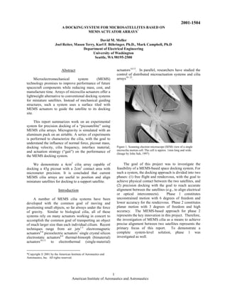
docking velocity, cilia frequency, interface material, Figure 1. Scanning electron microscope (SEM) view of a single
microcilia motion cell. The cell is approx. 1mm long and wide.
and actuation strategy (“gait”) on the performance of (Image by John Suh, 1997)
the MEMS docking system.
We demonstrate a 4cm2 cilia array capable of The goal of this project was to investigate the
docking a 45g picosat with a 2cm2 contact area with feasibility of a MEMS-based space docking system. For
micrometer precision. It is concluded that current such a system, the docking approach is divided into two
MEMS cilia arrays are useful to position and align phases: (1) free flight and rendezvous, with the goal to
miniature satellites for docking to a support satellite. achieve physical contact between the two satellites, and
(2) precision docking with the goal to reach accurate
Introduction alignment between the satellites (e.g., to align electrical
or optical interconnects). Phase 1 constitutes
A number of MEMS cilia systems have been unconstrained motion with 6 degrees of freedom and
developed with the common goal of moving and lower accuracy for the rendezvous. Phase 2 constitutes
positioning small objects, so far always under the force planar motion with 3 degrees of freedom and high
of gravity. Similar to biological cilia, all of these accuracy. The MEMS-based approach for phase 2
systems rely on many actuators working in concert to represents the key innovation in this project. Therefore,
accomplish the common goal of transporting an object the investigation of MEMS cilia as a means to achieve
of much larger size than each individual cilium. Recent precise alignment between two satellites represents the
techniques range from air jets1-3 electromagnetic primary focus of this report. To demonstrate a
actuators4-6 piezoelectric actuators7 single crystal silicon complete system-level solution, phase 1 was
electrostatic actuators8,9 thermal-bimorph (bimaterial) investigated as well.
actuators10-13 to electrothermal (single-material)
*Copyright ã 2001 by the American Institute of Aeronautics and
Astronautics, Inc. All rights reserved.
1
American Institute of Aeronautics and Astronautics
2. reliability and strength for use in miniature spacecraft
applications.
Figure 3. Envisioned microsatellite mission
Microsatellite Docking
Figure 2. Airtable experimental setup to simulate microsatellite
docking. An 8” × 6” perforated aluminum plate with 3 adjustable Figure 3 describes a large, broad purpose satellite
support screws provides levitation support for an aluminum puck surrounded by a constellation of smaller, mission
(“picosat”). Microcilia chips are mounted on a vertical copper plate
with heat sink. specific satellites. The miniature satellites provide
inspection, maintenance, assembly and communication
services for their larger brethren. One important future
During this project thermally actuated polyimide task for the microsatellites is inspecting the larger
based microcilia, as seen in Figure 1 and identical to satellite for damage. Cameras mounted on the
those published in Suh, et. al13, are extensively microsatellite provide imagery of the primary platform
characterized to ascertain their practicality for docking that is otherwise unobtainable. From these pictures,
miniature spacecraft. To this end, experiments were damage could be assessed and the mission of the main
performed using an airtable, seen in Figure 2, which satellite adapted. Due to their simplicity, small size,
was designed to support the microcilia in a vertical weight and limited interaction with ground controllers
configuration. A rectangular aluminum block, referred these specialized satellites are expected to be
to as a puck, which has a mass between 40g and 45g is indispensable during future missions23.
used to simulate a picosatellite. The airtable can be
tilted towards the microcilia producing a known normal
force against the faces of the chips. This force can then
be adjusted independently from the mass of the
simulated picosatellite. To increase the realism of the
experiment and to facilitate data collection, position
sensing and position feedback are incorporated and
computer controlled. Two position-sensing systems are
used: an array of Hall effect sensors and a video capture
based system. These are strictly non-contact techniques
compatible with a space environment.
Next we describe the experiments that were Figure 4. Conceptual cilia picosatellite docking application
performed with the microcilia with the goal to evaluate
the appropriateness of microcilia to spacecraft docking As the size of satellites shrink, their ability to carry
applications. The microcilia successfully moved blocks fuel and power is reduced. It is expected that this will
of aluminum in excess of 40g of mass and calculations force microsatellites to dock frequently to replenish
indicate that a patch of cilia 25cm in radius would be their resources. Since the time spent docking subtracts
sufficient to position a 40kg satellite. Four different from the microsatellites’ mission time, this procedure
materials, polished ceramic, polystyrene, smooth should be as simple and quick as possible. When
aluminum and silicon, both rough and polished, are docking microspacecraft there are two primary tasks:
used for the cilia to puck interface surface. Polished attaching the microsatellite to the larger craft, and
ceramic achieved the highest puck velocities of all orienting the satellite to connect fuel, data and electrical
interfaces and polished silicon attained higher velocities services. The first docking task is largely the domain of
than rough silicon. Throughout the course of this study the microsatellite and is dependent on how quickly
microcilia were able to provide the speed, robustness,
2
American Institute of Aeronautics and Astronautics
3. velocity adjustments can be made, and on the specific description of the cilia actuators and their operation was
attachment mechanism. The second phase of docking presented in Suh, et. al12,13.
is dependent on the speed at which the satellite can be
positioned to connect electrical and other services. An array of cilia is configured in an 8 × 8 motion
cell layout within a 1cm2 die. Each motion cell
Figure 4 shows the conceptual cilia application for contains four orthogonally-oriented actuators within an
space docking of miniature satellites. A surface on the area of 1.1mm × 1.1mm. A control line independently
mother satellite is covered with cilia actuators that will actuates each actuator of the motion cell. All actuators
position the picosatellite for refueling and data transfer. oriented in the same direction in each motion cell are
controlled in parallel.
The microcilia arm is placed into motion using a
titanium-tungsten heating resistor that is sandwiched
between the two silicon nitride and two polyimide
layers. When a current is passed through this loop, the
temperature of the actuator increases, and the structure
deflects downward. This produces both horizontal and
vertical displacements at the tip of the microcilia.
Objects in contact with the surface of the array are
made to move by coordinating the deflections of many
actuators. For this study both three and four-phase gaits
are used during the interface experiments but only the
Figure 5. Cross-sectional view of the cilia with two layers of
polyimide, titanium-tungsten heater loop, silicon-nitride stiffening
four-phase gait is used for the normal force
layer, and aluminum electrostatic plate. (Image by John Suh, 1997) experiments. The motions of the microcilia arms for the
four-phase gait are shown in Figure 6. This motion has
two transitions that produce forward motion.
Experimental Setup
The measurements in this paper are performed
using the thermal actuator based microcilia originally
described in Suh, et. al13. A cross-section of microcilia
arms is shown in Figure 5. The arrayed actuators are
deformable microstructures that curl out of the substrate
plane. The curling of the actuators is due to the
different CTE of the polyimide layers that make up the
bimorph structures. For these devices the top layer
CTE is greater than the bottom CTE. The thermal
stress from this interface causes the actuator to curl
away from the substrate at low temperatures and
towards it when heated. This stress also aids in Figure 6. The four phase cilia motion gait showing all phases of
motion
releasing the microcilia arms because they
automatically rise out of the plane when the sacrificial
layer is etched. The displacement of the microcilia arm The sequence of phases starts with both arms
relative to its location before release both vertically, δV, flattened. The west arm is released forcing the object
and horizontally, δH, is given by: up and to the east. Next, the east arm is released which
rises to make contact with the object. Then the west
æ æ L öö (1) arm is actuated leaving the east actuator to support the
δ V = Rç1 − cosç ÷ ÷
ç ÷ object. The final phase and start of a new phase in the
è è R øø
sequence results in the object moving down and to the
æLö (2) east. The three phase gait is the same as the four phase
δ H = L − R sinç ÷
èRø except the phase in top of Figure 6 is skipped.
where R (≈ 800µm) is the radius of curvature and L (≈
430µm) is the length of the motion actuator which To assess the applicability of microcilia to
results in a horizontal displacement, δH, of 20µm and spacecraft docking this study investigates the effects of:
vertical displacement, δV, of 114µm. A detailed operating frequency, normal force, interface surfaces,
microcilia temperature, and, indirectly, microcilia life
3
American Institute of Aeronautics and Astronautics
4. span. Of these variables, frequency and life span
depend directly on the thermal actuation nature of the
cilia while the remaining parameters should be
applicable to other types of MEMS microactuator
arrays.
To perform measurements the microcilia are placed
vertically, at the end of a tilted airtable as show in
Figure 7. The table is first leveled and then the angle
adjustment is manipulated to specify a slope running
Figure 8. Side view of the airtable
towards the microcilia. By adjusting the slope of the
table, the mass of the aluminum airtable puck can vary During all of the experiments the microcilia were
while the normal force against the microcilia remains controlled with the LabView interface seen in Figure 7
constant. Conversely, the mass can remain fixed while and custom circuitry. Each of the microcilia gaits is
a variable normal force is applied against the broken down into a statemachine describing the
microcilia. Using this parameter independence, the sequence of movements for each of the microcilia arms.
airtable allows for an accurate simulation of This statemachine is then loaded into a LSI
microsatellite docking in microgravity. programmable gate array, one per microcilia chip. The
LabView interface instructs the LSI chips which gait to
With this setup, the microcilia can manipulate use, the direction to travel and the frequency through
objects that would otherwise flatten the actuators if all which to cycle the cilia gait. LabView also reads the
the gravitational force were applied as the normal force. Hall effect sensor array and from that data controls the
This experiment uses four microcilia chips attached to a starting and ending points of the puck.
copper block that both actively cools the microcilia
using a Peltier junction and holds them vertical at the Video
Verticle Center
Signal
end of the airtable. The microcilia chips were glued Capture
Calculation
into a grove machined in the copper block, forcing all AND of Averageing and
Center Velocity Display Data
four chips to lie in the same plane in a horizontal linear Calculation Calculation
array. Image Conversion Horizontal Center
to Black and White Calculation
Clock
Store Data
0 Latest
MEASUR EMENT D AT A
1 Readings
4.5
4.0 2 0.04
3 0.03
3.5
3.0
2.5
4
5
0.09
0.17 Figure 9. Block flow diagram of image capture system
0.11
2.0 6
2.09
1.5 7
3.82
1.0 3.20
0.45
To make displacement measurements two separate
0.5
0.0 0.13
0.14
-0.5
systems are employed. The first is a high-resolution
2 3 4 5 6 7 8 9 10 11 12 0.06
0.02
4.5
video capture system. This system, equipped with a
0 1 2 3 4 5 6 7 8 9 10 11 12
4.0
3.5
zoom lens, allows for relative measurements on the
3.0 order of 5µm and for capturing expanded views of the
2.5
2.0
system. A video capture and distance measurement
1.5 system has been developed. A flow diagram, shown in
Real
0.00
Mean
6.21
1.0
0.5
Figure 9, details the specific tasks that are performed
0.0
0 1 2 3 4 5 6 7 8 9 10 11 12 upon a video image. The image of the puck is captured
0 1 2 3 4 5 6 7 8 9 10 11 12
using a black and white CCD camera mounted on a
Device Channels Data Log?
Data Log
Time Int erval
North
40 60
Gait
4 variable zoom, 1-10, microscope. This image is then
converted to a black and white image to allow
1 H0:H12
( ) 1
20
Current Time West 80
Sample Rate East Hz (0,1,2,3) 3
File Path (.txt or .xls (1ms * Interval
17.96
C:WINNTProfilesmasontPersonalHalldata_8Mar.
f t)
processing using Matlab.
1000 12.00 South 0 100 2
Figure 7. LabView interface for the microcilia
Once converted, the center points of both the
horizontal and vertical white regions are calculated.
After the center point calculations are complete, Matlab
performs an AND function to determine the center pixel
of the captured image. All of the center points can be
combined and averaged relative to an internal clock to
reduce the error of the capture system.
4
American Institute of Aeronautics and Astronautics
5. The other measurement system is an array of Hall frequencies the puck motion seems largely the result of
effect sensors. These sensors interact with a magnet a ‘step and carry’ transport. One conclusion from this
mounted atop the puck to provide micrometer graph is that the overall velocity of the puck increases
resolution. The Hall effect sensor array is integrated as the normal force against the cilia surface decreases to
into the LabView controlling software allowing fully a minimum normal force value. This is an expected
automated experiments to be performed. Using either result because as the normal force increases so does the
of these systems it is possible to collect relative puck precompression of the cilia, reducing their total vertical
position and from this to compute the velocity and and horizontal motion. This would indicate that the
acceleration of the puck. optimal normal force is that where the puck exerts just
sufficient force to maintain contact with the cilia
0.25 surface.
64uN/mm^2
59uN/mm^2 Effects of Interfacing Surfaces
0.2
49uN/mm^2
0.14
45uN/mm^2
Velocity (mm/s)
Ceramic3
0.15 Rough Si3
0.12 Plastic3
Aluminum3
Polished Si3
0.1 0.10
Velocity (mm/sec)
0.08
0.05
0.06
0
0 10 20 30 40 0.04
Drive Frequency (Hz)
0.02
Figure 10. The velocity of the airtable puck (using the beveled plastic
interface) versus different drive frequencies as a function of normal 0.00
forces 2.5 5.0 7.5 10.0 12.5 15.0 17.5 20.0 22.5 25.0 27.5 30.0 32.5 35.0
Frequency (Hz)
Experimental Results Figure 11. Influence of interface material on puck velocity using a
three-phase gait
The goal of this research is to evaluate the
applicability of microcilia arrays to microsatellite 0.250
docking. Thermal microcilia arrays are parameterized Ceramic4
for operating frequency, normal force, puck mass, Rough Si4
Plastic4
interface surfaces, cilia temperature and cilia lifespan. 0.200
Aluminum4
The results for these experiments are presented here. Polished Si4
Velocity (mm/sec)
0.150
Effects of Normal Force
Figure 10 shows the velocity of the puck at
0.100
different frequencies for four different normal forces.
For all of these data points the mass of the puck is
41.20gr and the interface surface is a 0.9cm × 2.5cm 0.050
piece of polystyrene, beveled on the edges. Each data
point is an average of four runs over a distance of
0.000
0.8mm. This setup contains two strong resonant 2.5 5.0 7.5 10.0 12.5 15.0 17.5 20.0 22.5 25.0 27.5 30.0 32.5 35.0
frequencies between 13 and 16Hz and between 30 and Frequency (Hz)
33Hz as illustrated by the graph flattening at these Figure 12. Influence of interface material on puck velocity using a
points. For these measurements the video system is four-phase gait
used to record the puck velocity.
Outside of these regions the puck velocity Differences between thermal conduction and
increases linearly which indicates the puck moving in surface roughness of the puck to microcilia interface
accordance to the driving period. This characteristic affect step size and puck velocity. The five puck-to -
indicates the interface between the puck and microcilia microcilia interface materials examined are: polished
arms is experiencing a fixed slip component. At these ceramic, hard polystyrene plastic, aluminum, polished
5
American Institute of Aeronautics and Astronautics
6. and unpolished silicon. Puck velocity versus frequency increased, this effect becomes less pronounced,
for the differing interface materials is shown in Figure however, it is still consistently observed. Within these
11 and Figure 12 for three and four-phase gaits, frequency bands the puck was observed to move away
respectively. Puck velocity is obtained by averaging a from the puck surface on the order of 100µm, lending
minimum of five trials per frequency with a normal support to this theory.
force of 63µN/mm2. The distance the puck traveled for
these measurements varies between 0.1mm to 0.6mm Thermal Effects
with increasing actuation frequency. As the background temperature of the microcilia is
0.12
allowed to increase the actuators become less effective.
With rising background temperature it takes longer for
Rough Si4
Polished Si4 the cilia to gain heat during the actuated portion of its
0.10
Rough Si3
Polished Si3
motion cycle. This results in a lowering of the
maximum available driving frequency. In the extreme
0.08
case the background temperature becomes large enough
Velocity (mm/sec)
that the heater loop cannot raise the temperature of the
0.06
cilia higher than the background. At this background
temperature, no heating period would be sufficient to
0.04 allow the cilia to have a net displacement. At this
point, objects in contact with the cilia would no longer
0.02 be transported.
0.00 This scenario was experimentally verified. If the
2.5 5.0 7.5 10.0 12.5 15.0 17.5 20.0 22.5 25.0 27.5 30.0 32.5 35.0
Frequency (Hz)
polarity of the Peltier junction that normally cools the
microcilia is reversed, it provides active heating, rather
Figure 13. Comparison of both rough and polished silicon interface than active cooling. As the background temperature of
for both three and four-phase gaits
the cilia increases, actuation displacement decreases.
Eventually all visible movement halts. Once this point
is reached the heater is turned off and the microcilia are
As summarized in Figure 13, the velocity of the allowed to cool. Subsequent checks of the microcilia,
puck is dependent on the material interfaced with the under standard operating conditions, could determine
microcilia. The thermal conduction of the interface no mechanical or electrical faults. However, prolonged
material is thought to be the major cause for the operation at elevated temperatures will eventually
variation in velocity magnitude per material. Surface damage the actuators. Possible failures include
roughness is also observed to have some influence, but charring of the polyimide and fusing of the heater wire.
to a much lesser extent. Aluminum and silicon have the
highest thermal conduction and this results in the lowest Life Span
velocities. Ceramic, an excellent thermal and electrical Over the course of these experiments the microcilia
insulator, delivers some of the highest velocities. Low are shown to be robust and the results reproducible. All
thermal conduction of the ceramic interface allows the
four chips, corresponding to 4 × 256 actuators were run
cilia to heat and cool in an optimal fashion resulting in
for approximately 150 hours at an average of 20Hz.
high actuation amplitudes and high velocities.
This corresponds to 10.8 million actuations. During
this time only one microcilia actuator leaf was lost due
Missing data points in the three-phase graph and
to a manufacturing defect. This failure was in an
the flatter areas of the other graphs are due to the puck
individual heater loop and probably corresponded to a
oscillating with zero or reduced velocity for multiple
local thickening of the material or contaminants in that
trials at that frequency. This effect is distributed over
area.
the entire cilia experimental surface. The regions of
17.5Hz and 33Hz show the most pronounced reduction
in puck velocity for both gaits and all interface
Novel Algorithms and Control Software
materials. The variation of this effect for different
Rendezvous & Docking
surface material and puck mass indicates that it is
Numerous studies have been made in the area of
strongly dependent upon the specific geometry of the
Rendezvous and Docking (R&D) of small satellites in
experiment. Regardless of this minor variation, it is
space. These studies generally involve small “satellite”
thought that this phenomenon can be traced partly to
robot vehicles moving in 2 nearly frictionless degrees
the puck breaking contact with the microcilia surface
of freedom on an air-bearing surface. Two primary
during part of the motion cycle. As the normal force is
approaches have traditionally been pursued. The first
6
American Institute of Aeronautics and Astronautics
7. of these approaches is the use of GPS-like signals and arc without saturating. The Fuga 15d camera is shown
Differential Carrier Phase GPS techniques as a means in Figure 14.
of sensing both the relative position and the relative
attitude of the two satellites. An example can be found
in Zimmerman and Cannon, Jr.25 To simulate the GPS
environment, several pseudolite transmitters were built
and installed around the perimeter of a laboratory.
Algorithms were then developed to extract relative
position and relative attitude from carrier phase
measurements.
The second primary approach has been the use of
Figure 14. The Fuga 15d Digital CMOS Camera
CCD, or camera-based sensing to determine relative
positions and attitudes between the sensor and the
target. An example of this approach can be found in Direct readout and random access are a substantial
Howard and Book26. This study, performed at NASA’s advantage over analog imagers. Classic CCD and even
Marshall Space Flight Center, employed a single CCD addressable Metal-Oxide-Semiconductor (MOS)
sensor and laser diodes to illuminate a target. The imagers of the “integrating” type must be read out after
images were then processed to determine navigation a defined integration time, and thus cannot be used as
data. This approach has been further developed by true random access devices. Analog cameras also
NASA and is currently being built as a prototype for require frame grabber hardware, whereas the full matrix
flight testing on the Space Shuttle. An important point of pixels, or any desired pixels, on the Fuga 15d can be
to note in this approach is the use of analog CCD simply scanned and read directly into a buffer.
sensors and frame-grabber hardware for target sensing.
Pixel data is read from the camera ROM through 8
2-D Puck Experiment parallel, digital output lines. Image processing
algorithms must use the intensity value corresponding
Experimental Approach to each pixel to determine the target location in each
The approach to R&D presented in this section is a camera image. A hardware solution was adopted to
variation of the approach taken by Howard and Book, handle image processing and data flow using an FPGA.
that is, the use of optical sensing and image processing Output lines from the cameras are mapped directly to
to determine relative navigation data. However, this the hardware, and all image processing analysis is
approach differs significantly from the work cited carried out by the FPGA processor.
above. Sensing is provided by two 512 × 512 Fuga 15d
digital CMOS cameras. The two cameras are mounted Stereo Imaging
parallel to one another, separated by a baseline distance.
In this configuration the cameras can determine range X
and attitude with respect to a target through stereo Image
imaging. Another significant difference is the absence (x1, y1)
of frame-grabber hardware for image capture, since the λ
cameras feature digital output. Z
B w
The Fuga 15d Digital CMOS Camera
Image
The use of digital, optical, CMOS cameras offers
many advantages over analog CCD cameras. The Fuga λ
15d, from the IMEC Company, is a 512×512 pixel, (x2, y2) Z
addressable imaging chip that behaves similar to a 256
Kbyte ROM. After reading an X-Y address, the pixel
intensity is directly read out and returned in a digital Plane of constant Z
word of 8 bits, allowing true random access. Direct
readout means that the output signal is an instantaneous Figure 15. Top view of the stereo imaging process (From Fu,
measure of the photocurrent. Camera response is Gonzalez and Lee28.)
logarithmic, which allows the chip to capture six or
more orders of magnitude of intensities in the same Much as in human vision, two cameras imaging the
image. As a result, the sensor is virtually immune to same target can provide sufficient information about the
blooming. The camera can take a picture of a welding orientation and location of the target27. The process of
7
American Institute of Aeronautics and Astronautics
8. mapping a 3D scene onto an image plane is a many-to-
one operation. This means that a single image point
does not uniquely determine the location of a
corresponding point in the 3-dimensional world. More
precisely, the range to a target cannot be accurately
determined from a single camera image. The missing
range information can be determined using stereo
imaging techniques.
The objective, stated in another way, is to find the
coordinates (X,Y,Z) of the point w given its image
points (x1, y1) and (x2, y2). It is assumed that the
cameras are identical and that the coordinate systems of
both cameras are perfectly aligned, differing only in the
locations of their origins, which are separated by the
baseline distance, B. Range information determined by Figure 16. 2-D Puck Experiment with integrated CMOS camera
the x-coordinate shift of the target location in each
camera image, or the quantity (x2-x1), using the
following equation: All sensor measurements are sent to a TattleTale 8
controller board (TT8), which includes a Motorola
λB
Z = λ − (3) 68332 microprocessor, a 500 Kbaud RS-232 interface
x 2 − x1 and a PIC 16C64 microcontroller operating as a super-
programmable clock. Data processing software and
The most challenging task in implementing the control algorithms are loaded into the EEPROM of the
stereo imaging approach is to accurately determine two 68332 microprocessor. The TT8 processes incoming
corresponding points in two different images of the sensor signals and sends control signals to the solenoid
same scene. However, with proper target design and valves, thus closing the loop.
image processing techniques, this can be reliably
accomplished. For example, the image might consist of Puck Control and Navigation – An Augmented
a series of concentric circles against a highly Approach
contrasting background. A simple algorithm could then While the puck is capable of fully autonomous
be developed to determine the pixel center of the navigation to accomplish rendezvous with the cilia
binarized image and, therefore, the target center. array, an augmented navigation and control approach is
more desirable. The puck will follow a predetermined
The 2-D Puck reference trajectory, passing through a waypoint. This
A 2-dimensional experiment has been developed strategy is to ensure that the final approach and contact
that will serve as a test bed for integration of sensors with the cilia is as perpendicular to the plane of the cilia
and for verification of control algorithms. The 2-D as can realistically be achieved with the control system
“Puck” consists of a series of vertically stacked decks, of the puck. This requirement is especially important to
floating upon a low-friction cushion of air supplied by avoid damage to the cilia arrays caused by a rendezvous
an on-board air system. The cameras are mounted near with lateral motion components, i.e., in the plane of the
the outer edge of the second deck and integrated cilia array. Such an interaction between the puck and
electronically to a central computer. Control is array could tear and damage the cilia actuators. An
accomplished with small solenoid valves that act as air illustration of the waypoint trajectory can be seen below
thrusters. Eight thrusters are placed around the in Figure 17. The initial navigation phase sends the
circumference of the second deck, enabling control in puck to the waypoint, which is somewhere removed
the +x, +y directions and spin control about the vertical from the final destination. The next phase directs the
axis. When placed on a sufficiently flat surface the puck puck to slowly approach the cilia array, holding the
can translate in two dimensions and rotate about its spin lateral (X) coordinate constant.
axis with very little friction. The goal of the
experiment is to electronically integrate and close the
loop with the CMOS sensors and to demonstrate
rendezvous with a stationary target.
8
American Institute of Aeronautics and Astronautics
9. Cilia
Results from the interface experiments indicate that
a variety of materials common to spacecraft can be used
as docking surfaces, including aluminum and silicon,
Y thus avoiding the need for special materials on the
mating surfaces. When studying the performance of
different interface materials, thermal conduction
dominates surface roughness to achieve optimal object
velocity. Surface roughness does affect object velocity
as seen in the polished and unpolished silicon. An
X
interface material, such as ceramic, with low thermal
conduction and little surface roughness should be
Figure 17. Table schematic and puck trajectory
selected for an optimal docking surface.
The dynamics of the puck were modeled and Using microcilia to perform the delicate final
included in a discrete-time simulation with LQR control orientation and positioning of the satellite will greatly
using the reference trajectories. Both the reference and speed up the docking operation because the entire
simulated paths are shown in Figure 18. In the lower satellite, with its fixed connections, could be mated to
curve, the ideal x trajectory ramps up to the desired fixed connections on the main satellite. This alleviates
value, corresponding to the waypoint, and subsequently the use of flexible and cumbersome umbilical cords and
remains constant. The y coordinate ramps up to the attendant positioning systems.
waypoint coordinate and from that point follows a
slowly increasing parabolic input to slowly approach A further benefit of using microcilia as a docking
the final position at the cilia array. The simulation surface is a reduction in mass compared to other
closely tracked the reference trajectory and final docking and alignment techniques. On the host satellite
position using LQR control. only a surface of microcilia is required along with
minimal control electronics and sensors. The microcilia
docking system could simply replace one of the
satellite’s body panels for maximum weight savings.
On the microsatellite side, the additional mass to
incorporate docking functionality could be as low as
zero. The optimal microcilia interface is a flat plane,
which may already be part of the microsatellite chassis,
thus requiring minimal integration.
The microcilia themselves have inherent
advantages for this application. Foremost among these
advantages is their ability to arbitrarily position the
satellite anywhere on the surface and in any orientation.
The microcilia can also act as sensors, however, it has
already been demonstrated that they can position
objects open loop with little loss of accuracy18. By
using thousands of microcilia on a single docking
Figure 18. Closed loop response to reference trajectory using LQR
control. patch, it is possible to build systems that incorporate
massive redundancy. Thus, if there is some kind of
Conclusions docking mishap the entire mission need not be affected.
Finally, thermal microcilia have been shown to perform
The results from these experiments indicate that a better in vacuum then air24. This is largely due to a lack
microcilia surface can be useful for docking small of convective cooling which slows the heating cycle.
spacecraft. These spacecraft, used for inspection,
maintenance, assembly and communication services, The scalability of microcilia also enables the
will see increased use as space missions become more construction of widely varied systems. While the
autonomous and far reaching23. During this scenario, primary task envisioned for microcilia is manipulating
microcilia provide a good match, allowing for simple picosatellites (mass <1kg) much greater masses are
docking procedures to be used with these simple feasible. By using additional cilia and a greater contact
satellites. area, larger microsatellites can be handled. The current
9
American Institute of Aeronautics and Astronautics
10. generation of microcilia is capable of moving a 41.2g Conf. on Solid-State Sensors and Actuators, vol. 1,
puck with an interface area of 2cm2. This indicates that Chicago, IL, June 16–19, 1997, pp. 37–40.
a patch only 25cm in radius (100,000 times as large as 4. C. Liu, T. Tsai, Y.-C. Tai, W. Liu, P. Will, and C.-
the area in the experiment) would be sufficient to M. Ho, “A micromachined permalloy magnetic
position satellites with more than 40kg mass under actuator array for micro robotics assembly
microgravity conditions. systems,” in Transducers ’95 Dig. 8th Int. Conf. on
Solid-State Sensors and Actuators/Eurosensors IX,
Throughout the course of this study the microcilia vol. 1, Stockholm, Sweden, June 1995, pp. 328–
exhibited the speed, robustness, reliability and strength 331.
needed for this application. These results show that 5. W. Liu and P. Will, “Parts manipulation on an
microcilia can be an attractive alternative to intelligent motion surface,” in Proc. 1995
conventional docking systems for microsatellite IEEE/RSJ Int. Conf. on Intelligent Robots and
applications. Systems, Pittsburg, PA, vol. 3, Aug. 5–9, 1995, pp.
399–404.
Acknowledgments 6. H. Nakazawa, Y. Watanabe, and O. Morita, “The
two-dimensional micro conveyor: Principles and
This report describes work on “Smart fabrication process of the actuator,” in Transducers
Attachments” performed under AFRL prime contract ’97 Dig. 9th Int. Conf. on Solid-State Sensors and
F29601-98-D-0210, USRA subcontract 9500-20, Actuators, vol. 1, Chicago, IL, June 16–19 1997,
8/24/99 - 8/23/00. Team members were Dr. Karl F. pp. 33–36.
Böhringer (PI), Department of Electrical Engineering, 7. T. Furihata, T. Hirano, and H. Fujita, “Array-
and Dr. Mark Campbell (co-PI), Department of driven ultrasonic microactuators,” in Transducers
Aeronautics and Astronautics, University of ’91 Dig. 6th Int. Conf. on Solid State Sensors and
Washington, Seattle, WA. Joel Reiter, Mason Terry Actuators, San Francisco, CA, June 1991, pp.
(UW EE), and David M. Meller (UW AA) were 1056–1059.
graduate students working on this project. Dr. R. 8. K.-F. Böhringer, B. R. Donald, and N. C.
Bruce Darling (UW EE), Dr. Gregory T. A. Kovacs MacDonald, “Single-crystal silicon actuator arrays
(Department of Electrical Engineering, Stanford for micro manipulation tasks,” in Proc. IEEE 9th
University, CA), and Dr. John W. Suh (Xerox Palo Alto Workshop on Micro Electro Mechanical Systems
Research Center, CA) were informal consultants. (MEMS), San Diego, CA, Feb. 1996, pp. 7–12.
9. K.-F. Böhringer, B. R. Donald, N. C. MacDonald,
The authors wish to thank Mike Sinclair for the “Programmable Vector Fields for Distributed
manufacture of the airtable setup and for many Manipulation, with Applications to MEMS
inspiring discussions. We are grateful to the members Actuator Arrays and Vibratory Parts Feeders.”
of the University of Washington MEMS Laboratory, International Journal of Robotics Research,
and the members and staff of the Washington 18(2):168-200, February 1999.
Technology Center Microfabrication Laboratory. 10. N. Takeshima and H. Fujita, “Polyimide bimorph
Fabrication of the microcilia arrays was supported by actuators for a ciliary motion system,” in ASME
DARPA and NSF. Development of cilia control WAM, Symp. Micromech. Sensors, Actuators, and
strategies was supported by NSF. Systems, DSC-vol. 32, 1991, pp. 203–209.
11. M. Ataka, A. Omodaka, and H. Fujita, “A
References biomimetic micro motion system,” in Transducers
’93 Dig. 7th Int. Conf. on Solid State Sensors and
1. K. S. J. Pister, R. Fearing, and R. Howe, “A planar Actuators, Pacifico, Yokohama, Japan, June 1993,
air levitated electrostatic actuator system,” in Proc. pp. 38–41.
IEEE 5th Workshop on Micro Electro Mechanical 12. J. W. Suh, S. F. Glander, R. B. Darling, C. W.
Systems, Napa Valley, CA, Feb. 1990, pp. 67–71. Storment, and G. T. A. Kovacs, “Combined
2. S. Konishi and H. Fujita, “A conveyance system organic thermal and electrostatic omnidirectional
using air flow based on the concept of distributed ciliary microactuator array for object positioning
micro motion systems,” J. Microelectromech. Syst., and inspection,” in Tech. Dig. Solid-State Sensors
vol. 3, no. 2, 1994, pp. 54–58. and Actuator Workshop, Hilton Head, SC, June
3. Y. Mita, S. Konishi, and H. Fujita, “Two 1996, pp. 168–173.
dimensional micro conveyance system with 13. J. W. Suh, S. F. Glander, R. B. Darling, C. W.
through holes for electrical and fluidic Storment, and G. T. A. Kovacs, “Organic thermal
interconnection,” in Transducers ’97 Dig. 9th Int. and electrostatic ciliary microactuator array for
10
American Institute of Aeronautics and Astronautics
11. object manipulation,” Sensors and Actuators, A: 25. Zimmerman, K. R. and Cannon, Jr., R. H.,
Physical, vol. A58, 1997, pp. 51–60. “Experimental Demonstration of GPS for
14. T. Ebefors, J. U. Mattsson, E. Kèlvesten, and G. Rendezvous Between Two Prototype Space
Stemme, “A robust micro conveyor realized by Vehicles.” In Proceedings of the 8th International
arrayed polyimide joint actuators,” in Proc. IEEE Technical Meeting of the Satellite Division of the
12th Workshop on Micro Electro Mechanical Institute of Navigation, Palm Springs, CA, Sept.
Systems (MEMS), Orlando, FL, Jan. 1999, pp. 576– 12-15, 1995. Pt. 2 (A96-15026 02-17), Alexandria,
581. VA, Institute of Navigation, 1995, p. 1905-1913.
15. P. E. Kladitis, V. M. Bright, K. F. Harsh, and Y. C. 26. Howard, Richard T. and Book, Michael L.
Lee, “Prototype microrobotics for micro “Improved Video Guidance Sensor for Automated
positioning in a manufacturing process and micro Docking.” In Space guidance, control and
unmanned vehicles,” in Proc. IEEE 12th Workshop tracking II; Proceedings of the Third Conference,
on Micro Electro Mechanical Systems (MEMS), Orlando, FL, Apr. 17, 18, 1995 (A95-37727 10-
Orlando, FL, Jan. 1999, pp. 570–575. 19), Bellingham, WA, Society of Photo-Optical
16. H. Fujita, “Group work of microactuators,” in Int. Instrumentation Engineers (SPIE Proceedings. Vol.
Adv. Robot Program Workshop on Micromachined 2466), 1995, p. 118-127.
Technologies and Systems, Tokyo, Japan, Oct. 27. Gonzalez, Rafael C. Digital Image Processing.
1993, pp. 24–31. Addison-Wesley Publishing Company, Inc., 1987.
17. Böhringer, K., Donald, B., Mihailovich, R., 28. Fu, K. S., Gonzalez, R. C., and Lee, C. S. G., 1987.
MacDonald, N.C., 1994, “A Theory of Robotics: Control, Sensing, Vision and
Manipulation and Control for Microfabricated Intelligence, McGraw-Hill, New York.
Actuator Arrays,” Proceedings, IEEE MEMS ’94,
pp. 102-104.
18. W. Liu and P. Will, “Part manipulation on an
intelligent motion surface,” in IEEE/RSJ Int.
Workshop on Intelligent Robots & Systems (IROS),
vol. 3, Pittsburg, PA, Aug. 1995, pp. 399–404.
19. Böhringer, K., Suh, J., Donald, B., Kovacs, G.,
1997, “Vector fields for task-level distributed
manipulation: experiments with organic micro
actuator arrays,” Proceedings, 1997 IEEE
International Conference on Robotics and
Automation, vol. 2, pp. 1779-1786.
20. K.-F. Böhringer, B. R. Donald, N. C. MacDonald,
“Programmable Vector Fields for Distributed
Manipulation, with Applications to MEMS
Actuator Arrays and Vibratory Parts Feeders.”
International Journal of Robotics Research,
18(2):168-200, February 1999.
21. Mita, Y., Kaiser, A., Stefanelli, B., Garda, P.;
Milgram, M., Fujita, H., 1999, “A distributed
microactuator conveyance system with integrated
controller,” Proceedings, IEEE SMC '99, vol.1, pp.
18–21.
22. K.-F. Böhringer and Howie Choset, Distributed
Manipulation, Kluwer Academic Publishers, 272
pp., ISBN 0-7923-7728-1, January 2000.
23. Campbell, M., Böhringer, K., 1999, “Intelligent
Satellite Teams for Space Systems,” Proceedings,
2nd Int. Conf. on Integrated
Micro/Nanotechnology for Space Applications, vol.
2, pp. 193-204.
24. Darling, R., Suh, J., Kovacs, G., 1998, “Ciliary
Microactuatory Array for Scanning Electron
Microscope Positioning Stage,” J. Vac. Sci. Tech.
A, vol. 16, no. 3, pp. 1998-2002, May/Jun.
11
American Institute of Aeronautics and Astronautics