The document discusses modelling fluid flow in shale reservoirs. It describes the complex porous network in shales which includes multiple gas storage and transport mechanisms. Effective modelling requires accounting for different porosity systems including the organic matrix, inorganic pores and natural fractures. Common modelling approaches for fractured reservoirs like dual porosity and dual permeability models are discussed as well as their limitations for modelling low permeability shales. More advanced models like MINC (Multiple INteracting Continua) and locally refined dual permeability models are presented to better represent transient fluid flow in shales. Key shale properties affecting gas production including adsorbed gas, non-Darcy flow, and fracture properties are also summarized.
![shale rock properties
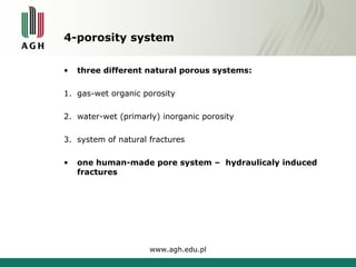
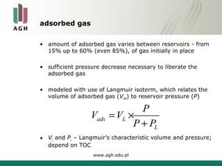
• variety of shale rock types => different types of shale gas
reservoirs
• four important characteristics :
1. maturity of organic matter
(vitrinite reflectance [%Ro]; > 1% Ro)
2. type of gas generated and stored in the reservoir
(thermogenic or biogenic)
3. TOC content of the strata (min. 1.0 wt%)
4. permeability of the reservoir
(0.00001-0.001mD = 10-1000 nD)
www.agh.edu.pl](https://image.slidesharecdn.com/agh-eera8-9-141122090639-conversion-gate01/85/Agh-eera-8-9-10-2014-4-320.jpg)


![Geotechnical Engineering-I [Lec #14A: Soil Compaction - Problem Sheet]](https://cdn.slidesharecdn.com/ss_thumbnails/14-180923184507-thumbnail.jpg?width=640&height=640&fit=bounds)


