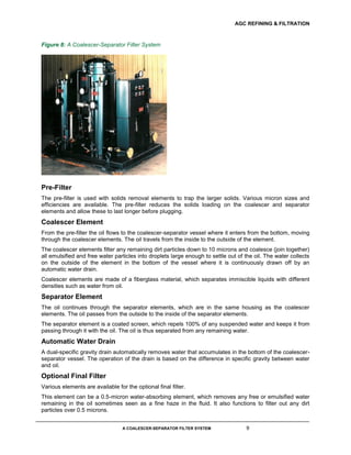
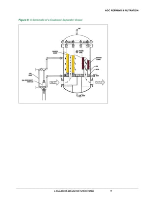
2. AGC REFINING & FILTRATION
A COALESCER-SEPARATOR FILTER SYSTEM 2
Contents
The Theory of Coalescence 3
Dynamic Coalescer-Separator Systems 3
The System 8
3. AGC REFINING & FILTRATION
A COALESCER-SEPARATOR FILTER SYSTEM 3
The Theory of Coalescence
When two liquids are immiscible, or not soluble in each other, they can form an emulsion or a colloidal
suspension. In these types of mixtures the dispersed liquid (water) forms droplets in the continuous phase
(oil or fuel). For instance, in a water-diesel fuel mixture the diesel fuel is the continuous phase and the
water will exist as droplets of various sizes.
Traditionally, gravity separators were used in liquid-liquid systems to promote the coalescing of the
dispersed phase. In these systems differences in densities of the two liquids cause droplets to rise or fall
according to their buoyancy. The greater the differences in densities the easier the separation is, as rising
or falling droplets (water) are acted upon by the frictional forces exerted by the viscosity of the continuous
phase (oil or diesel fuel). This mechanism is governed by Stoke’s Law.
When the movement of the continuous phase (oil or diesel fuel) is slow as in a gravity settler, the effect of
the inertial force is reduced and the buoyant force and the gravity force are equal. This is termed as the
terminal velocity of the droplet.
A critical factor in a gravity (static) settler is the residence time. It has to be long enough to allow for the
passive process of merging smaller droplets into larger ones.
Figure 1: Stoke’s Law
Dynamic Coalescer-Separator Systems
In dynamic coalescers the merging of many small droplets to form fewer droplets of a larger diameter is
accelerated by interposing a barrier into the fluid flow in the form of fibers. In this method of direct
interception the fibers collect the fine droplets as they travel in laminar flow between the fiber mass. This
has the general effect of greatly reducing the residence time in the coalescer. An added feature of the
fiber mass is that it will also trap solids and thus a pre-filter is required to remove solids from the fluid
stream and increase the efficiency and longevity of the coalescer and separator elements.
4. AGC REFINING & FILTRATION
A COALESCER-SEPARATOR FILTER SYSTEM 4
Figure 2: A Typical Outer Layer of a Coalescer Element Consisting of a Dense Glass-Fiber Matrix (500x
Magnification)
Coalescer Element Design
The coalescing process can be thought of as occurring in three steps.
Step 1
The first step in coalescing is the collection of droplets by direct interception on the fibers. It is important
that the flow through the glass-fiber mass is as close to laminar flow as possible. The general rule is that
the diameter of the glass fibers must be as close to the average diameter of the droplets as possible.
Figure 3: The Inner Layer Also Traps Solid Particles (500x Magnification)
Step 2
The second step is the coalescence of the droplets that have been captured on the fibers. This happens
when droplets collide with each other. The critical design factors are the material of the fibers and the
speed at which the droplets travel through the fiber mass.
The coalescer medium (fiber) can be either hydrophilic (water-loving) or oleophilic (oil-loving), depending
on the solid/liquid interfacial tension between the medium and the dispersed phase (water). In general, an
organic dispersed phase will “wet” an organic medium (plastic or glass fiber). This helps in the
coalescence step as the droplets adhere to the medium longer and increase the chances of collisions
with other droplets.
The density of the medium also influences coalescence. A tightly packed medium increases the number
of sites available for coalescing.
When two droplets interact during flight, several events can occur. The droplets may experience bounce,
5. AGC REFINING & FILTRATION
A COALESCER-SEPARATOR FILTER SYSTEM 5
stable coalescence, temporary coalescence followed by disruption, or temporary coalescence followed by
fragmentation.
Droplet Bounce
Droplet bounce will occur if the surfaces of the droplets do not make contact due to the presence of a thin
intervening liquid film. The droplets undergo a flattening deformation, but the surfaces do not make
contact since the kinetic energy of the collision is not sufficient to rupture the intervening boundary layer
of film.
Figure 4: Droplet Bounce
Droplet Coalescence
If the mass of two combining droplets is equal to the sum of the masses of each droplet, the intervening
liquid film is ruptured. This contact between the two droplets is followed by coalescence.
Figure 5: Droplet Coalescence
Temporary Coalescence Followed By Disruption
Temporary coalescence will occur when the kinetic energy of collision exceeds the values for stable
coalescence. This will result in disruption or fragmentation. In disruption, the droplets surfaces have made
contact, but the energy of collision was too great thus temporary coalescence is followed by disruption,
resulting in the same number of droplets which existed prior to the collision.
6. AGC REFINING & FILTRATION
A COALESCER-SEPARATOR FILTER SYSTEM 6
Figure 6: Temporary Coalescence Followed By Disruption
Temporary Coalescence Followed By Fragmentation
Fragmentation is the result of excessive fluid velocities in the fiber matrix. The energy of the collisions
between droplet is so great that the result is a fragmentation into smaller droplets.
Figure 7: Temporary Coalescence Followed By Fragmentation
Coalescence is improved in laminar flow conditions since the droplets will stay in the streamlines around
the fibers. High fluid velocities overcome surface tension forces and strip droplets out of the coalescer
medium. These collisions result in breakup and re-entrainment of the droplets. Laminar fluid flow
velocities also result in optimum residence time and allow the droplets to impact with each other without
disintegrating.
Step 3
The third step is the collection of coalesced water droplets in the bottom of the coalescer vessel. The
optimum degree of separation depends on the geometry of the vessel and timely removal of the collected
liquid from the bottom by an automatic, dual-specific gravity drain.
Separator Element Design
Separator elements consist of screens coated with various hydrophobic (water repellent) material. The
elements are used as a second stage in a coalescer-separator system. Their sole function is to repel
coalesced water droplets produced by the coalescer element while allowing hydrocarbon fluids to pass
through.
Water droplets settle into the vessel sump and are prevented from passing downstream of the system.
Flow direction is from the outside of the element to the inside and to the outlet of the coalescer-separator
7. AGC REFINING & FILTRATION
A COALESCER-SEPARATOR FILTER SYSTEM 7
vessel.
Factors Influencing Coalescer Performance
Forms of Water
Two forms of water can exist in oils or fuels, dissolved or suspended as small droplets that range in size
from 0.1 to 10 microns. The free water is trapped as an emulsion. The more stable the emulsion is, the
more difficult it is to separate the water.
Factors that affect water removal from a water/oil or fuel mixture are:
Interfacial tension
Viscosity
Relative density
Temperature
Interfacial Tension
The ability to coalesce a dispersed phase (water) from a continuous phase (oil/fuel) improves as the
interfacial tension increases. The formation of the largest possible stable droplet size by coalescence
depends on the interfacial tension. A mixture with a high interfacial tension will result in relatively larger
stable droplet sizes. This is important when a coalescer is used to dehydrate turbine lube oil.
Factors that lower the interfacial tension are various additives such as inhibitors and detergents. Solids
contamination will also reduce the interfacial tension. For this reason, a pre-filter is often used to reduce
the solids content and increase the life of the coalescer elements.
Viscosity
Viscosity has a profound effect on coalescence. Droplets must travel through the continuous phase to
collide and coalesce by breaking down the intervening boundary layer. Both of these factors are
influenced by increased viscosity. Droplets must overcome the increased drag force of higher viscosities.
The breakdown of the intervening boundary layer between droplets is also more difficult to overcome.
Therefore, longer residence times and higher differential pressures across the coalescer vessel are
required for liquids with higher viscosities. This can be achieved by lowering the flow rate or increasing
the coalescer element surface area.
Relative Density
The relative density between the water phase and the oil/fuel phase is important because as the two
relative densities approach equality, the separation becomes more difficult.
Temperature
As the temperature of the oil/fuel and water mixture is increased, the interfacial tension is decreased. This
results in smaller droplet sizes. In addition, mixtures at higher temperatures can contain higher levels of
dissolved water, which cannot be removed by coalescers. As the temperature decreases, water comes
out of solution and can be removed by coalescence.
For this reason, coalescer systems should be installed in the coolest possible location. Heaters are not
generally used in coalescer systems.
Design flow through the coalescer element is inversely proportional to the fluid viscosity in Cst.
The separator stage is velocity-limited but is not affected by increased viscosity
8. AGC REFINING & FILTRATION
A COALESCER-SEPARATOR FILTER SYSTEM 8
General Design Considerations
The two-stage coalescer-separator system has the following limitations:
The coalescer stage is limited by the differential pressure and the viscosity of the mixture
When the maximum velocity through the separator is reached, water will break through into the
effluent
Generally, a larger coalescer stage is used with the same size separator to enable handling higher flows
for more viscous fluids. Because lower viscosity fluids like gasoline are limited by the separator, a larger
coalescer stage does not improve the flow rate.
Description of the Process
In liquid-liquid coalescers, the merging of droplets can occur whenever two or more droplets collide and
remain in contact long enough for the continuous-phase film, which exists around each droplet, to
become so thin that a hole develops in the boundary layer. This allows the liquid droplets to merge and
become larger droplets. In a clean system with high interfacial tension, coalescence will occur rapidly.
Particulates and polymeric films tend to accumulate at the droplet surfaces and reduce the rate of
coalescence. This can lead to a build-up of a “rag” layer at the liquid-liquid interface in a coalescer
system.
Coalescers are mats, beds, or layers of porous or fibers whose properties are especially suited for this
purpose. It has been found in studies that coalescence is promoted by decreased fiber diameter. A
minimum bed density and residence time is required to achieve complete coalescence depending on the
characteristics of the fluids and the coalescer system. Wetting of the fibers by droplets of the dispersed
phase is not necessary for good coalescence.
The System
The Allen Coalescer System removes free and emulsified water down to the saturation level. The
saturation level is a function of the type of oil, the types of additives in the oil, and the temperature of the
oil. For typical ISO 32 Turbine Light Oil at 100°F (38°C), the saturation level is approximately 150 parts
per million (ppm).
The complete Allen system consists of a pre-filter vessel, a coalescer-separator vessel, and an optional
final filter.
9. AGC REFINING & FILTRATION
A COALESCER-SEPARATOR FILTER SYSTEM 9
Figure 8: A Coalescer-Separator Filter System
Pre-Filter
The pre-filter is used with solids removal elements to trap the larger solids. Various micron sizes and
efficiencies are available. The pre-filter reduces the solids loading on the coalescer and separator
elements and allow these to last longer before plugging.
Coalescer Element
From the pre-filter the oil flows to the coalescer-separator vessel where it enters from the bottom, moving
through the coalescer elements. The oil travels from the inside to the outside of the element.
The coalescer elements filter any remaining dirt particles down to 10 microns and coalesce (join together)
all emulsified and free water particles into droplets large enough to settle out of the oil. The water collects
on the outside of the element in the bottom of the vessel where it is continuously drawn off by an
automatic water drain.
Coalescer elements are made of a fiberglass material, which separates immiscible liquids with different
densities such as water from oil.
Separator Element
The oil continues through the separator elements, which are in the same housing as the coalescer
elements. The oil passes from the outside to the inside of the separator elements.
The separator element is a coated screen, which repels 100% of any suspended water and keeps it from
passing through it with the oil. The oil is thus separated from any remaining water.
Automatic Water Drain
A dual-specific gravity drain automatically removes water that accumulates in the bottom of the coalescer-
separator vessel. The operation of the drain is based on the difference in specific gravity between water
and oil.
Optional Final Filter
Various elements are available for the optional final filter.
This element can be a 0.5-micron water-absorbing element, which removes any free or emulsified water
remaining in the oil sometimes seen as a fine haze in the fluid. It also functions to filter out any dirt
particles over 0.5 microns.
10. AGC REFINING & FILTRATION
A COALESCER-SEPARATOR FILTER SYSTEM 10
An economical cellulose filter element can also be used for the purpose of adsorbing any water remaining
in the fluid. Several micron-size elements can be used to obtain final ISO standard cleanliness grades.
Table 1: The Solubility of Water in Oil
11. AGC REFINING & FILTRATION
A COALESCER-SEPARATOR FILTER SYSTEM 11
Figure 9: A Schematic of a Coalescer-Separator Vessel