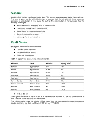
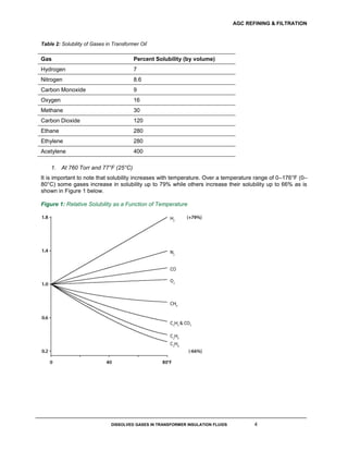
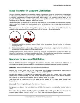
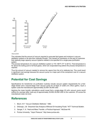
Dissolved Gases in Transformer
Insulation Fluids
WHITE PAPER
© 2017 AGC Refining & Filtration LLC
AGC REFINING & FILTRATION
DISSOLVED GASES IN TRANSFORMER INSULATION FLUIDS 2
Contents
General 3
Fault Gases 3
Mass Transfer in Vacuum Distillation 5
Moisture in Vacuum Distillation 5
Potential for Cost Savings 6
References 6
AGC REFINING & FILTRATION
DISSOLVED GASES IN TRANSFORMER INSULATION FLUIDS 3
General
Insulation fluid inside a transformer breaks down. This process generates gases inside the transformer.
The types of gases can be related to the type of electrical fault; the rate at which these gases are
generated is an indication of how severe the fault is. The determination of the fault gases has the
following advantages:
 Advance warning of developing faults in the transformer
 Determining improper use of the transformer
 Status checks on new and repaired units
 Convenient scheduling of repairs
 Monitoring of units under overload
Fault Gases
Fault gases are created by three conditions:
 Corona or partial discharge
 Pyrolysis of thermal heating
 Arcing (the most severe)
Table 1: Typical Fault Gases Found in Transformer Oil
Fault Gas Type Formula Boiling Point
1
Methane Hydrocarbon CH4 -164
Ethane Hydrocarbon C2H6 -89
Ethylene Hydrocarbon C2H4 -103
Acetylene Hydrocarbon C2H2 -84
Hydrogen Hydrocarbon H2 -252.9
Carbon Dioxide Carbon Oxide CO2 -56.6
Carbon Monoxide Carbon Oxide CO -192.5
Nitrogen Non-Fault Gas N2 -195.8
Oxygen Non-Fault Gas O2 -183.0
1. In °C at 750 Torr
These gases accumulate in the oil as well as in the headspace above the oil. The way gases dissolve in
oil is a function of their solubility and temperature.
The following table shows the solubility of fault gases from the least soluble (hydrogen) to the most
soluble (acetylene) at a static equilibrium of 760 Torr and 77°F (25°C).
AGC REFINING & FILTRATION
DISSOLVED GASES IN TRANSFORMER INSULATION FLUIDS 4
Table 2: Solubility of Gases in Transformer Oil
1
Gas Percent Solubility (by volume)
Hydrogen 7
Nitrogen 8.6
Carbon Monoxide 9
Oxygen 16
Methane 30
Carbon Dioxide 120
Ethane 280
Ethylene 280
Acetylene 400
1. At 760 Torr and 77°F (25°C)
It is important to note that solubility increases with temperature. Over a temperature range of 0–176°F (0–
80°C) some gases increase in solubility up to 79% while others increase their solubility up to 66% as is
shown in Figure 1 below.
Figure 1: Relative Solubility as a Function of Temperature
AGC REFINING & FILTRATION
DISSOLVED GASES IN TRANSFORMER INSULATION FLUIDS 5
Mass Transfer in Vacuum Distillation
Vacuum distillation is a method of distillation whereby the pressure above the liquid mixture to be distilled
is reduced to less than its vapor pressure (usually less than atmospheric pressure) causing evaporation
of the most volatile liquid(s) (those with the lowest boiling points). This distillation method works on the
principle that boiling occurs when the vapor pressure of a liquid exceeds the ambient pressure. Vacuum
distillation can be used with or without heating the solution.
The heat provides the energy for the dissolved gas molecules to escape the liquid phase and become
vapor. In the form of vapor they are evacuated to the condensate tank where they are condensed and
disposed of.
The vapor pressure of a liquid is the equilibrium pressure of a vapor above its liquid form that is the
pressure of the vapor resulting from evaporation from the liquid at a certain temperature.
1. Microscopic equilibrium between gas and liquid at low temperature. A small number of molecules
escaping into gas.
2. Microscopic equilibrium between gas and liquid at high temperature. A large number of molecules are
escaping into the gas phase due to the energy input.
At a higher temperature, more molecules get enough energy to escape from the liquid phase. This is the
function of the heater in the vacuum distillation process. It provides enough energy for the mass transfer
of the contaminant molecules to become gas and be removed by the vacuum.
Moisture in Vacuum Distillation
Vacuum distillation lowers the boiling point of substances, including water in oil. Figure 2 below is a
nomograph that allows the determination of the boiling point for substances under vacuum conditions.
Example 1: Determining the Boiling Point of a Liquid Under Vacuum
Assume your vacuum pump pulls 20 Torr (2,666.4 Pa) and you want to determine the boiling point of
water at that vacuum. The normal boiling point of water is 100°C (212°F).
Using a ruler, draw a line from 20 Torr on the pressure graph to the right through 100°C in the middle
graph (boiling point corrected to 760 Torr—normal atmospheric pressure) and where this line intersects
the line to the left (observed boiling point) take the reading. About 15°C, right?
This means that at a vacuum of 20 Torr, water will boil already at 15°C—well below normal room
temperature.
Example 2: Determining the Strength of an Unknown Vacuum
Using water, we observe that water boils over at 40°C. You know the normal boiling point of water is
100°C.
Draw a line through 40°C in the left graph through 100°C in the middle graph. The line intersects the
pressure graph at about 100 Torr (13,332.2 Pa). This is how much vacuum the pump will pull.
AGC REFINING & FILTRATION
DISSOLVED GASES IN TRANSFORMER INSULATION FLUIDS 6
This indicates that the amount of vacuum required to evacuate fault gases and moisture in vacuum
distillation systems is far less than originally thought. This caused an impression on the part of customers
that relatively large capacity vacuum systems needed to be specified for a single-pass purification
system.
The process temperature of a vacuum distillation system is 170–180°F (77° to 82°C). That temperature is
far above the boiling point of all fault gases, which are evaporated long before the process temperature is
reached.
Thus the amount of vacuum needed to remove the vapors from the oil is relatively low. This could result
in significant cost savings because the vacuum pump is a major part of the component cost of a vacuum
distillation system.
Potential for Cost Savings
Specifications for transformer oil purification routinely include vacuum system requirements for a first-
stage blower and a second-stage main vacuum pump for oil flows of 3,000 L/hr (792.5 gal/hr). Such a
system costs the manufacturer approximately 25,000–30,000 USD.
Applying the mass transfer calculations would reveal that a single-stage 20 scfm vacuum pump would
suffice at a savings (after mark-up) of approximately 35,000–55,000 USD to the customer. Of course the
manufacturer does not mind.
References
1. Bloch, H.P. “Vacuum Distillation Methods.” 1960.
2. DiGiorgio, J.B. “Dissolved Gas Analysis of Mineral Oil Insulating Fluids.” NTT Technical Bulletin.
3. Gengel, Y. A. “Heat and Mass Transfer, a Practical Approach.” McGraw-Hill.
4. Purdue University. “Vapor Pressure.” http://www.purdue.edu.
www.AGCInternational.com
3045 East Elm Street
Springfield, Missouri 65802, USA
Toll Free: +1 800 865 3208
Phone: +1 417 865 2844

Agc wp-dissolved gases in transformer insulation fluids

  • 1.
    Dissolved Gases inTransformer Insulation Fluids WHITE PAPER © 2017 AGC Refining & Filtration LLC
  • 2.
    AGC REFINING &FILTRATION DISSOLVED GASES IN TRANSFORMER INSULATION FLUIDS 2 Contents General 3 Fault Gases 3 Mass Transfer in Vacuum Distillation 5 Moisture in Vacuum Distillation 5 Potential for Cost Savings 6 References 6
  • 3.
    AGC REFINING &FILTRATION DISSOLVED GASES IN TRANSFORMER INSULATION FLUIDS 3 General Insulation fluid inside a transformer breaks down. This process generates gases inside the transformer. The types of gases can be related to the type of electrical fault; the rate at which these gases are generated is an indication of how severe the fault is. The determination of the fault gases has the following advantages:  Advance warning of developing faults in the transformer  Determining improper use of the transformer  Status checks on new and repaired units  Convenient scheduling of repairs  Monitoring of units under overload Fault Gases Fault gases are created by three conditions:  Corona or partial discharge  Pyrolysis of thermal heating  Arcing (the most severe) Table 1: Typical Fault Gases Found in Transformer Oil Fault Gas Type Formula Boiling Point 1 Methane Hydrocarbon CH4 -164 Ethane Hydrocarbon C2H6 -89 Ethylene Hydrocarbon C2H4 -103 Acetylene Hydrocarbon C2H2 -84 Hydrogen Hydrocarbon H2 -252.9 Carbon Dioxide Carbon Oxide CO2 -56.6 Carbon Monoxide Carbon Oxide CO -192.5 Nitrogen Non-Fault Gas N2 -195.8 Oxygen Non-Fault Gas O2 -183.0 1. In °C at 750 Torr These gases accumulate in the oil as well as in the headspace above the oil. The way gases dissolve in oil is a function of their solubility and temperature. The following table shows the solubility of fault gases from the least soluble (hydrogen) to the most soluble (acetylene) at a static equilibrium of 760 Torr and 77°F (25°C).
  • 4.
    AGC REFINING &FILTRATION DISSOLVED GASES IN TRANSFORMER INSULATION FLUIDS 4 Table 2: Solubility of Gases in Transformer Oil 1 Gas Percent Solubility (by volume) Hydrogen 7 Nitrogen 8.6 Carbon Monoxide 9 Oxygen 16 Methane 30 Carbon Dioxide 120 Ethane 280 Ethylene 280 Acetylene 400 1. At 760 Torr and 77°F (25°C) It is important to note that solubility increases with temperature. Over a temperature range of 0–176°F (0– 80°C) some gases increase in solubility up to 79% while others increase their solubility up to 66% as is shown in Figure 1 below. Figure 1: Relative Solubility as a Function of Temperature
  • 5.
    AGC REFINING &FILTRATION DISSOLVED GASES IN TRANSFORMER INSULATION FLUIDS 5 Mass Transfer in Vacuum Distillation Vacuum distillation is a method of distillation whereby the pressure above the liquid mixture to be distilled is reduced to less than its vapor pressure (usually less than atmospheric pressure) causing evaporation of the most volatile liquid(s) (those with the lowest boiling points). This distillation method works on the principle that boiling occurs when the vapor pressure of a liquid exceeds the ambient pressure. Vacuum distillation can be used with or without heating the solution. The heat provides the energy for the dissolved gas molecules to escape the liquid phase and become vapor. In the form of vapor they are evacuated to the condensate tank where they are condensed and disposed of. The vapor pressure of a liquid is the equilibrium pressure of a vapor above its liquid form that is the pressure of the vapor resulting from evaporation from the liquid at a certain temperature. 1. Microscopic equilibrium between gas and liquid at low temperature. A small number of molecules escaping into gas. 2. Microscopic equilibrium between gas and liquid at high temperature. A large number of molecules are escaping into the gas phase due to the energy input. At a higher temperature, more molecules get enough energy to escape from the liquid phase. This is the function of the heater in the vacuum distillation process. It provides enough energy for the mass transfer of the contaminant molecules to become gas and be removed by the vacuum. Moisture in Vacuum Distillation Vacuum distillation lowers the boiling point of substances, including water in oil. Figure 2 below is a nomograph that allows the determination of the boiling point for substances under vacuum conditions. Example 1: Determining the Boiling Point of a Liquid Under Vacuum Assume your vacuum pump pulls 20 Torr (2,666.4 Pa) and you want to determine the boiling point of water at that vacuum. The normal boiling point of water is 100°C (212°F). Using a ruler, draw a line from 20 Torr on the pressure graph to the right through 100°C in the middle graph (boiling point corrected to 760 Torr—normal atmospheric pressure) and where this line intersects the line to the left (observed boiling point) take the reading. About 15°C, right? This means that at a vacuum of 20 Torr, water will boil already at 15°C—well below normal room temperature. Example 2: Determining the Strength of an Unknown Vacuum Using water, we observe that water boils over at 40°C. You know the normal boiling point of water is 100°C. Draw a line through 40°C in the left graph through 100°C in the middle graph. The line intersects the pressure graph at about 100 Torr (13,332.2 Pa). This is how much vacuum the pump will pull.
  • 6.
    AGC REFINING &FILTRATION DISSOLVED GASES IN TRANSFORMER INSULATION FLUIDS 6 This indicates that the amount of vacuum required to evacuate fault gases and moisture in vacuum distillation systems is far less than originally thought. This caused an impression on the part of customers that relatively large capacity vacuum systems needed to be specified for a single-pass purification system. The process temperature of a vacuum distillation system is 170–180°F (77° to 82°C). That temperature is far above the boiling point of all fault gases, which are evaporated long before the process temperature is reached. Thus the amount of vacuum needed to remove the vapors from the oil is relatively low. This could result in significant cost savings because the vacuum pump is a major part of the component cost of a vacuum distillation system. Potential for Cost Savings Specifications for transformer oil purification routinely include vacuum system requirements for a first- stage blower and a second-stage main vacuum pump for oil flows of 3,000 L/hr (792.5 gal/hr). Such a system costs the manufacturer approximately 25,000–30,000 USD. Applying the mass transfer calculations would reveal that a single-stage 20 scfm vacuum pump would suffice at a savings (after mark-up) of approximately 35,000–55,000 USD to the customer. Of course the manufacturer does not mind. References 1. Bloch, H.P. “Vacuum Distillation Methods.” 1960. 2. DiGiorgio, J.B. “Dissolved Gas Analysis of Mineral Oil Insulating Fluids.” NTT Technical Bulletin. 3. Gengel, Y. A. “Heat and Mass Transfer, a Practical Approach.” McGraw-Hill. 4. Purdue University. “Vapor Pressure.” http://www.purdue.edu.
  • 7.
    www.AGCInternational.com 3045 East ElmStreet Springfield, Missouri 65802, USA Toll Free: +1 800 865 3208 Phone: +1 417 865 2844