Download to read offline
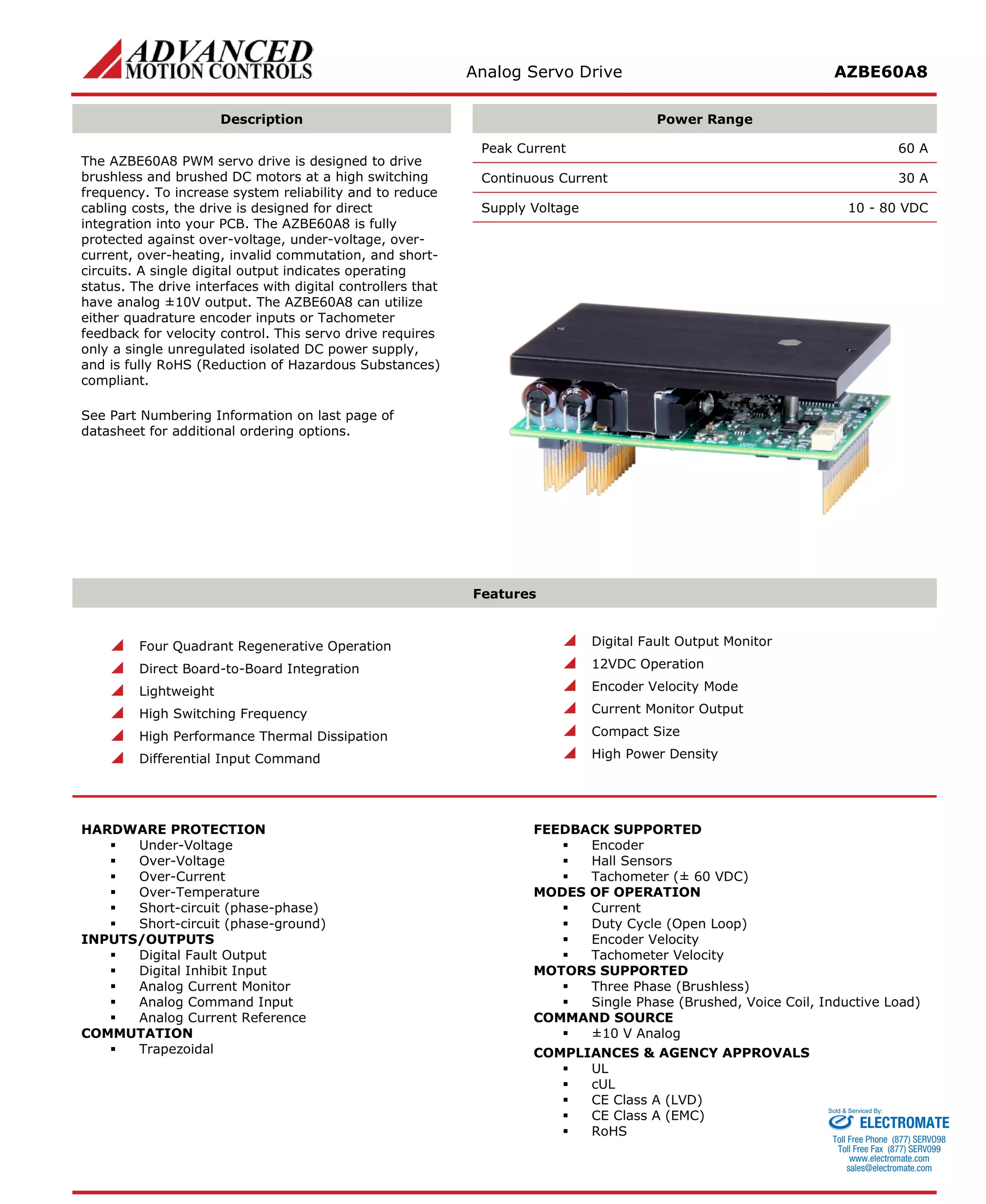
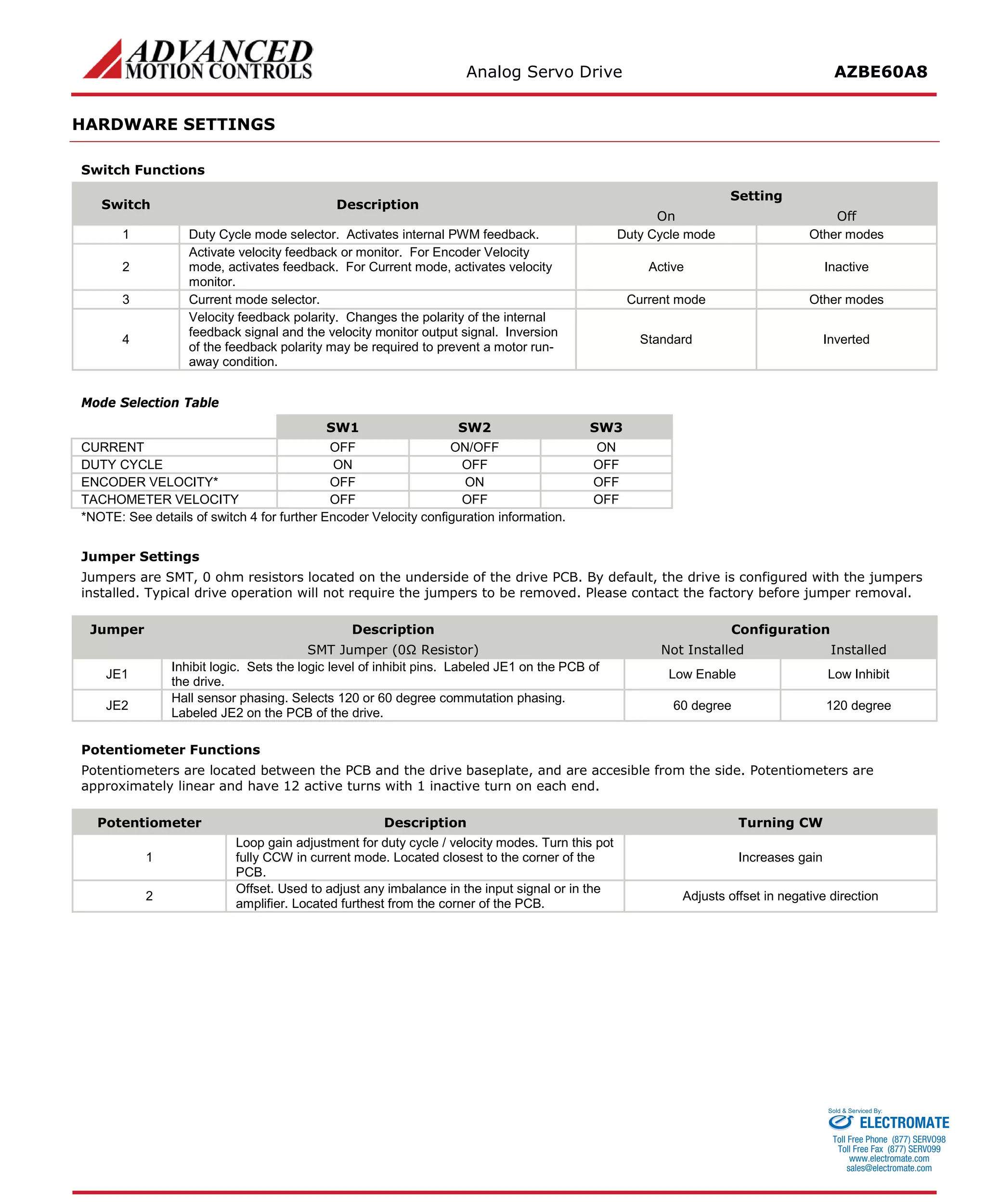
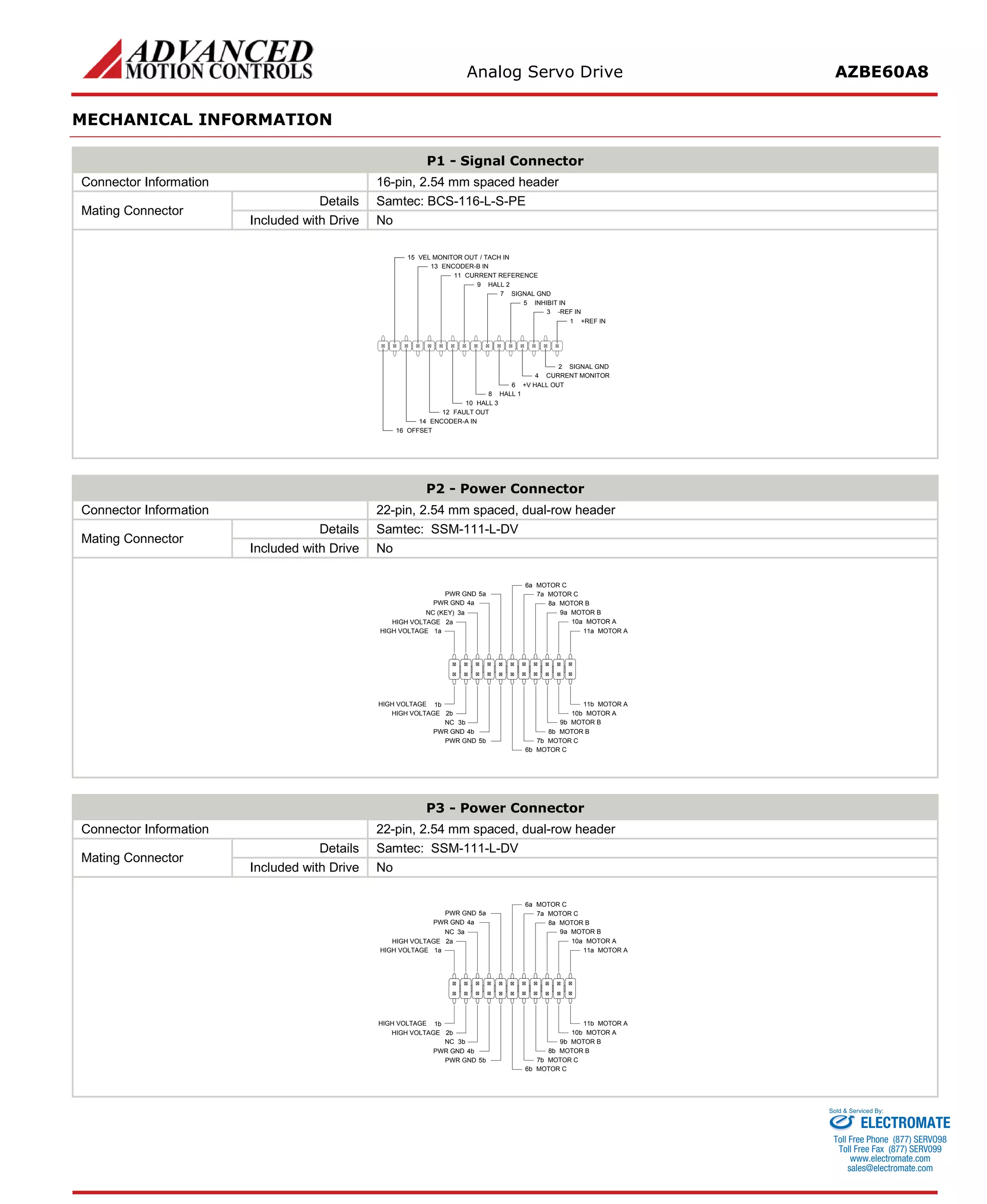
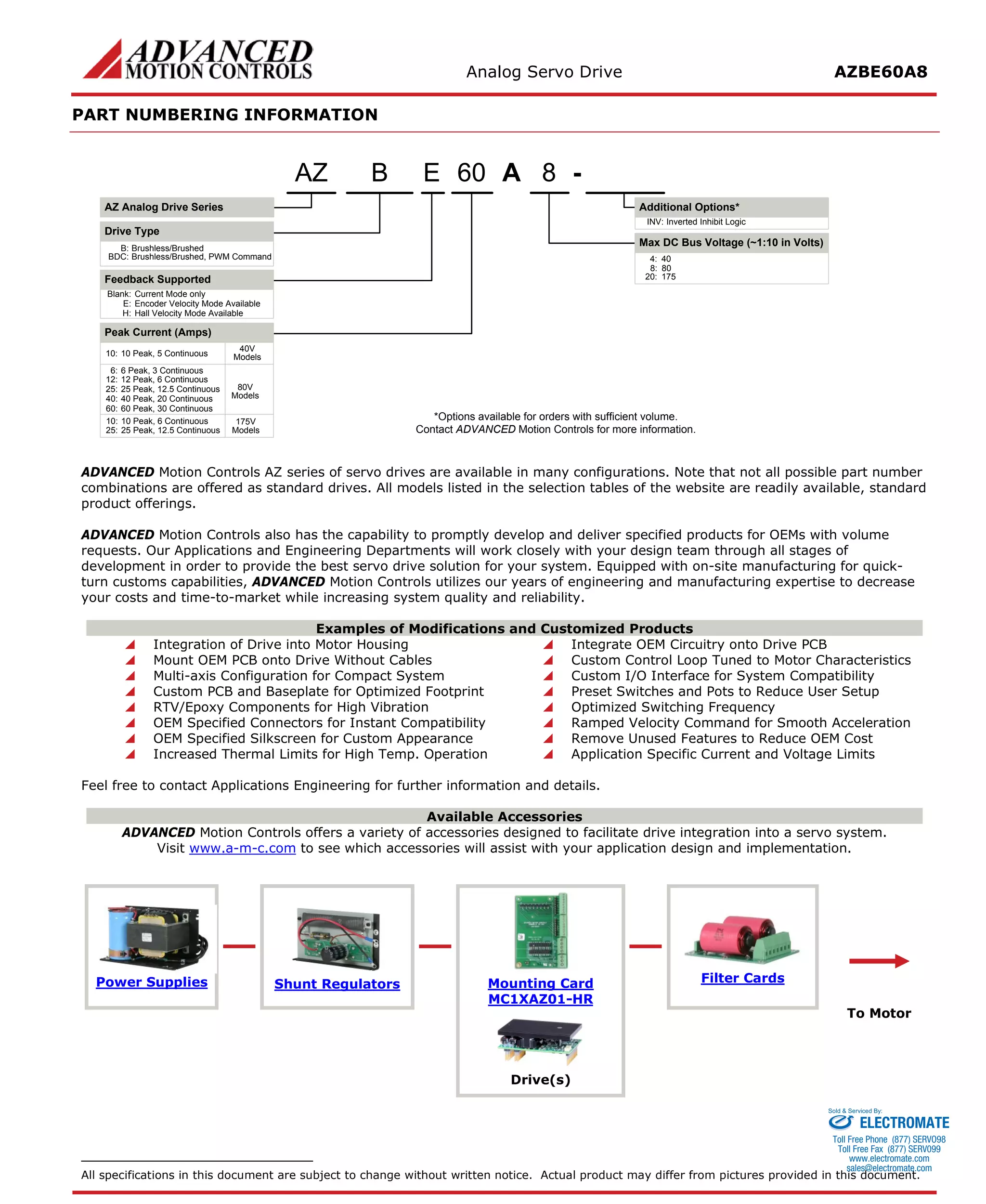

The document describes an analog servo drive called the AZBE60A8. It is designed to drive brushless and brushed DC motors at high switching frequencies. Key specifications include a peak current of 60A, continuous current of 30A, and operating voltage range of 10-80VDC. It has protection against overvoltage, undervoltage, overcurrent and more. It can utilize encoder, hall sensor, or tachometer feedback and supports various motor and operation modes.


