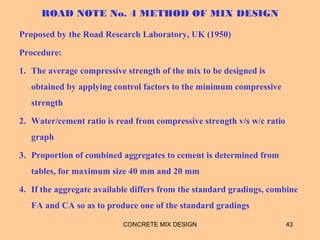
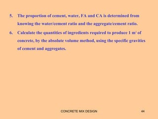
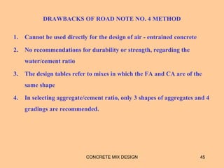
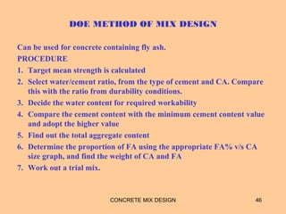
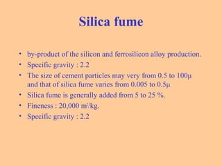
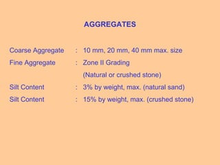
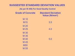
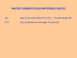
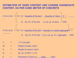
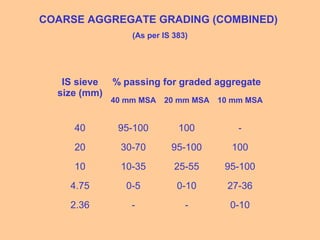
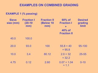
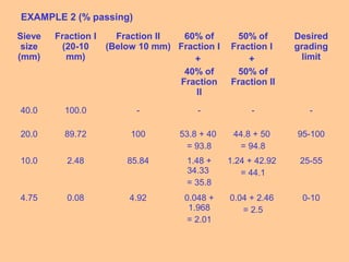
The document discusses various aspects of concrete mix design including:
1. Materials used in concrete like cement, aggregates, water, and admixtures.
2. Types of concrete mixes including nominal and design mixes.
3. Trial mixes are conducted to verify the design mix proportions before use.
4. Mix design is defined as determining relative proportions of ingredients to achieve desired properties economically. Factors like strength, workability, and durability must be considered.
5. Methods for concrete mix design discussed include ACI, BIS, and Road Note No. 4 methods. Proportions are adjusted based on aggregate properties and desired concrete performance.
Introduction to building technology and management focusing on concrete mix design.
Details the primary ingredients for concrete, including cement, aggregates, water, and admixtures.
Explanation of Nominal and Design Mix types, with nominal mixes for concrete strength M20 or lower.
Describes the process of preparing trial mixes to verify optimal design mix performance and adjustments.
Clarifies the science of concrete mix design aimed at achieving desired properties economically.
Lists key principles guiding the mix design including exposure conditions, concrete grade, and aggregate type.
Identifies crucial factors affecting mix proportions such as compressive strength, workability, and durability.
Describes Abram's Law on compressive strength and defines workability and durability of fresh concrete.
Outlines different methods for concrete mix design, including ACI, IS methods, and others available.
Processes under the ACI method including data collection and strength estimation based on design standards.
A design example utilizing ACI method for an elevated water tank with specific strength criteria.
Highlights factors affecting water-cement ratio according to strength and durability requirements.
Details calculations for mixing water, considering aggregate size and density for concrete design.
Presents estimated quantities of materials for concrete mix along with necessary adjustments for field conditions.
Reiterates strength criteria based on required compressive strength and slump for quality control.
Explains the Road Note No. 4 method for concrete mix design, its steps, and drawbacks.
Describes the DOE method for concrete mix design including target mean strength and mix proportions.Discusses updates to the BIS recommended method for concrete mix design reflecting on advancements.
Lists final steps in determining actual mix quantities and verifying calculated proportions for the mix.
Presents a design example under BIS recommendations, specifying mix proportions for concrete characteristics.
Details characteristics and specifications for various concrete materials, including cement and aggregates.
Emphasizes the relationship between water-cement ratio and compressive strength of concrete mixtures.
Guides on estimating mixing water and sand content based on required workability and grading types.
Establishes grading guidelines for fine aggregates impacting overall concrete quality and performance.
Addresses the standards for incorporating fly ash and aggregate content in concrete for enhanced durability.Techniques for estimating air content within concrete mixtures considering aggregate sizes.
Examples of combined grading techniques demonstrating practical applications for achieving ideal aggregate mixes.
TYPES OF CONCRETEMIXES
1. NOMINAL MIX
Mixes of fixed proportions, IS:456-2000 permits nominal mixes for
concretes of strength M20 or lower
2. DESIGN MIX
Designed on the basis of requirements of the concrete in fresh and
hardened states.
3CONCRETE MIX DESIGN
4.
TRIAL MIXES
Prepared toverify whether the Design Mix would perform as per the
assumptions. If appreciable variation exists, the available alternatives
are:
1. directly employ the trial mix proportions at the site
2. modify the trial mix proportions on the basis of intuition and employ
the revised proportions at the site
3. prepare further trial mixes incorporating changes in the proportions
based on the feedback generated from the previous mix.
4CONCRETE MIX DESIGN
5.
CONCRETE MIX DESIGN
DEFINITION
“Mix Design is the science of determining the relative proportions of
the ingredients of concrete to achieve the desired properties in the
most economical way.”
CONCRETE MIX DESIGN 5
6.
PRINCIPLES OF MIXDESIGN
1 The environment exposure condition for the structure
2 The grade of concrete, their characteristic strength’s and standard
deviations
3 The type of cement
4 The types and sizes of aggregates and their sources of supply
5 The nominal maximum sizes of aggregates
6 Maximum and minimum cement content in kg/m3
7 Water cement ratio
8 The degree of workability of concrete based on placing conditions
CONCRETE MIX DESIGN 6
7.
9 Air contentinclusive of entrained air
10 The maximum/minimum density of concrete
11 The maximum/minimum temperature of fresh concrete
12 Type of water available for mixing and curing
13 The source of water and the impurities present in it.
CONCRETE MIX DESIGN 7
FACTORS DEFINING THECHOICE OF MIX
PROPORTIONS
1. Compressive Strength
2. Workability
3. Durability
4. Type, size and grading of aggregates
5. Aggregate-cement ratio
CONCRETE MIX DESIGN 11
12.
COMPRESSIVE STRENGTH
Abram’s Law
logF = log A1 – x log B1
where F is the compressive strength
A1, B1 are constants and
x is the w/c ratio by weight
CONCRETE MIX DESIGN 12
13.
WORKABILITY
“that property offreshly mixed concrete which determines the ease
and homogeneity with which it can be mixed, placed, consolidated and
finished.”
DURABILITY
“the resistance to weathering action due to environmental conditions
such as changes in temperature and humidity, chemical attack,
abrasion, frost and fire.”
CONCRETE MIX DESIGN 13
14.
METHODS OF CONCRETEMIX DESIGN
1. American Concrete Institute Committee 211 method
2. Bureau of Indian Standards Recommended method IS 10262-82
3. Road note No. 4 (Grading Curve) method
4. Department Of Environment (DOE - British) method
5. Trial and Adjustment Method
6. Fineness modulus method
7. Maximum density method
8. Indian Road Congress, IRC 44 method
CONCRETE MIX DESIGN 14
15.
American Concrete InstituteMethod of Mix Design
(a) Data to be collected :
(i ) Fineness modulus of selected F.A.
(ii ) Unit weight of dry rodded coarse aggregate.
(iii ) Sp. gravity of coarse and fine aggregates in SSD condition
(iv ) Absorption characteristics of both coarse and fine aggregates.
(v ) Specific gravity of cement.
(b) From the minimum strength specified, estimate the average design
strength by using standard deviation.
(c) Find the water/cement ratio from the strength and durability points of
view. Adopt the lower value.
CONCRETE MIX DESIGN 15
16.
(d) Decide themaximum size of aggregate to be used. Generally for RCC
work 20 mm and pre-stressed concrete 10 mm size are used.
(e) Decide workability in terms of slump for the given job.
(f ) The total water in kg/m3
of concrete is determined, corresponding to
the selected slump and selected maximum size of aggregate.
(g ) Cement content is computed by dividing the total water content by
the water/cement ratio.
(h) Select the bulk volume of dry rodded coarse aggregate per unit
volume of concrete, for the particular maximum size of coarse
aggregate and fineness modulus of fine aggregate.
CONCRETE MIX DESIGN 16
17.
( j )The weight of C.A. per cubic meter of concrete is calculated by
multiplying the bulk volume with bulk density.
(k ) The solid volume of coarse aggregate in one cubic meter of concrete is
calculated by knowing the specific gravity of C.A.
(l ) Similarly the solid volume of cement, water and volume of air is
calculated in one cubic meter of concrete.
(m) The solid volume of FA is computed by subtracting from the total
volume of concrete the solid volume of cement, CA, water and
entrapped air.
(n) Weight of fine aggregate is calculated by multiplying the solid volume
of fine aggregate by specific gravity of F.A.
CONCRETE MIX DESIGN 17
18.
ACI METHOD: DESIGNEXAMPLE
1 Design a concrete mix for the construction of an elevated water tank.
The specified design strength of concrete (characteristic strength) is 30
MPa at 28 days measured on standard cylinders. Standard deviation
can be taken as 4 MPa. The specific gravity of FA and C.A. are 2.65
and 2.7 respectively. The dry rodded bulk density of C.A. is 1600
kg/m3, and fineness modulus of FA is 2.80. Ordinary Portland cement
(Type I) will be used. A slump of 50 mm is necessary. C.A. is found to
be absorptive to the extent of 1% and free surface moisture in sand is
found to be 2 per cent. Assume any other essential data.
CONCRETE MIX DESIGN 18
19.
1 Mean CylinderCompressive Strength
Assuming 5 per cent of results are allowed to fall below specified
design strength,
The mean strength,
fm= fmin + ks
= 30 + 1.64 x 4
= 36.5 MPa
2 Water/cement ratio
Strength criteria
Durability criteria
CONCRETE MIX DESIGN 19
CONCRETE MIX DESIGN24
The mixing water content is 185 kg/m3
of concrete
The approximate entrapped air content is 2%.
The required cement content =185/0.47
= 394 kg/m3
25.
CONCRETE MIX DESIGN25
4 Bulk Volume of C.A.
Maximum size of C.A = 20mm
Fineness Modulus of F.A. = 2.80
Find the dry rodded bulk volume of C.A.
CONCRETE MIX DESIGN27
The dry rodded bulk volume of C.A. = 0.62 per unit volume of
concrete
The weight of C.A. = 0.62 x 1600
= 992 kg/m3
28.
CONCRETE MIX DESIGN28
5 The first estimate of density of fresh concrete = 2355 kg/m3
29.
CONCRETE MIX DESIGN29
The weight of all the known ingredients of
concrete
Weight of water = 185 kg/m3
Weight of cement = 394 kg/m3
Weight of C.A. = 992 kg/m3
Weight of F.A. = 2355 – (185 + 394 + 992)
= 784 kg/m3
6 Weight of FA
30.
CONCRETE MIX DESIGN30
Alternatively, the weight of F.A. can be determined by the more
accurate absolute volume method
Absolute Volume = weight/(1000ρ) m3
31.
CONCRETE MIX DESIGN31
Total absolute volume = 697 x 103
cm3
Absolute volume of F.A. = (1000 – 697) x 103
= 303 x 103
Weight of FA = 303 x 2.65
= 803 kg/m3
32.
CONCRETE MIX DESIGN32
7 Estimated quantities of materials per cubic meter of
concrete are:
Cement = 394 kg
F.A = 803 kg
C.A = 992 kg
Water = 185 kg
33.
CONCRETE MIX DESIGN33
8 Proportions
C : F.A : C.A : water
394 : 803 : 992 : 185
1 : 2.04 : 2.52 : 0.47
Weight of materials for one bag mix
in kg = 50 : 102 : 126 : 23.5
34.
CONCRETE MIX DESIGN34
9 The above quantities is on the basis that both F.A
and C.A are in saturated and surface dry condition
(SSD conditions).
FA has surface moisture of 2%
Total free surface moisture in FA = (2/100 x 803)
= 16.06 kg/m3
Weight of F.A in field condition = 803 + 16.06 = 819.06 kg/m3
35.
CONCRETE MIX DESIGN35
Quantity of water absorbed by C.A. = (1/100 x 992) = 9.92 kg/m3
Weight of C.A in field condition = 992 – 9.92
= 982 kg/m3
C.A absorbs 1% water
Water contributed by F.A = 16.06 kg
Water absorbed by C.A. = 9.92 kg
Extra water contributed by aggs. = 16.06 – 9.92 = 6.14 kg
Total water content = 185.00 – 6.14
= 179 kg/m3
Change in Water Content
36.
CONCRETE MIX DESIGN36
Cement = 394 kg/m3
F.A. = 819 kg/m3
C.A. = 982 kg/m3
Water = 179 kg/m3
Field density of fresh concrete = 2374
kg/m3
Quantities of materials to be used in field, corrected for
free surface moisture in F.A and absorption characteristic
of C.A
37.
2. A mixwith a mean 28-day compressive strength of 35 MPa and a
slump of 50 mm is required, using OPC. The maximum size of well
shaped, angular aggregate is 20mm, its bulk density is 1600 kg/m3
and
its specific gravity is 2.64. The available fine aggregate has a fineness
modulus of 2.60 and a specific gravity of 2.58. No air-entrainment is
required.
CONCRETE MIX DESIGN 37
Water/Cement ratio
As durability criteria is not
mentioned, consider strength alone
Composition of concrete(kg/m3
)
Water = 185
Cement = 386
CA = 1020
FA = 738
Density of Concrete = 2329 (kg/m3
)
CONCRETE MIX DESIGN 42
43.
ROAD NOTE No.4 METHOD OF MIX DESIGN
Proposed by the Road Research Laboratory, UK (1950)
Procedure:
1. The average compressive strength of the mix to be designed is
obtained by applying control factors to the minimum compressive
strength
2. Water/cement ratio is read from compressive strength v/s w/c ratio
graph
3. Proportion of combined aggregates to cement is determined from
tables, for maximum size 40 mm and 20 mm
4. If the aggregate available differs from the standard gradings, combine
FA and CA so as to produce one of the standard gradings
CONCRETE MIX DESIGN 43
44.
5. The proportionof cement, water, FA and CA is determined from
knowing the water/cement ratio and the aggregate/cement ratio.
6. Calculate the quantities of ingredients required to produce 1 m3
of
concrete, by the absolute volume method, using the specific gravities
of cement and aggregates.
CONCRETE MIX DESIGN 44
45.
DRAWBACKS OF ROADNOTE NO. 4 METHOD
1. Cannot be used directly for the design of air - entrained concrete
2. No recommendations for durability or strength, regarding the
water/cement ratio
3. The design tables refer to mixes in which the FA and CA are of the
same shape
4. In selecting aggregate/cement ratio, only 3 shapes of aggregates and 4
gradings are recommended.
CONCRETE MIX DESIGN 45
46.
DOE METHOD OFMIX DESIGN
Can be used for concrete containing fly ash.
PROCEDURE
1. Target mean strength is calculated
2. Select water/cement ratio, from the type of cement and CA. Compare
this with the ratio from durability conditions.
3. Decide the water content for required workability
4. Compare the cement content with the minimum cement content value
and adopt the higher value
5. Find out the total aggregate content
6. Determine the proportion of FA using the appropriate FA% v/s CA
size graph, and find the weight of CA and FA
7. Work out a trial mix.
CONCRETE MIX DESIGN 46
47.
BIS RECOMMENDED MIXDESIGN METHOD
The BIS recommended mix design procedure is covered in IS 10262-
82.
In line with IS 456-2000, the first revision IS 10262-2009 was
published, to accommodate some of the following changes:
• Increase in strength of cement
• Express workability in terms of slump, rather than the compacting
factor
• Extend the W/C ratio v/s compressive strength graph
CONCRETE MIX DESIGN 47
MIX DESIGN BASEDON IS RECOMMENDATIONS
Based on IS 10262:1982
Procedure:
CONCRETE MIX DESIGN 49
1. Target mean strength for mix design:
fck* = fck + tS
where fck = characteristic compressive strength at
28 days
S = standard deviation
t = a statistical value depending on the
risk factor.
5. Calculation ofCement Content:
cement by mass = Water content/Water cement ratio
To be checked against the minimum cement content for the requirement of
durability and the greater of the two values to be adopted.
CONCRETE MIX DESIGN 56
7. Actual quantitiesrequired for mix
Adjust the mix for deviations from assumed conditions
CONCRETE MIX DESIGN 58
8. Check the calculated mix
proportions
59.
DESIGN EXAMPLE: BISRECOMMENDED METHOD
Grade M20
(a ) Design stipulations
(i ) Characteristic compressive strength
required in the field at 28 days - 20 MPa
(ii ) Maximum size of aggregate - 20 mm (angular)
(iii ) Degree of workability - 0.90 compacting factor
(iv ) Degree of quality control - Good
(v ) Type of Exposure - Mild
60.
(b) Test datafor Materials
(i ) Specific gravity of cement - 3.15
(ii ) Compressive strength of cement at 7 days - Satisfies the requirement
of IS: 269–1989
(iii ) 1. Specific gravity of coarse aggregates - 2.60
2. Specific gravity of fine aggregates - 2.60
(iv ) Water absorption:
1. Coarse aggregate - 0.50%
2. Fine aggregate - 1.0%
(v ) Free (surface) moisture:
1. Coarse aggregate - Nil
2. Fine aggregate - 2.0%
61.
Design Procedure
1. Targetmean strength of concrete
fck* = fck + tS
CONCRETE MIX DESIGN 61
fck = 20, t = 1.64 , S = 4
fck* = 26.6 MPa
4. Determination ofcement content
Water-cement ratio = 0.50
water = 191.6 kg/m3
CONCRETE MIX DESIGN 67
Cement = 191.6/0.50 = 383 kg/m3
Is this satisfactory for ‘mild’ exposure condition?
68.
5. Determination ofcoarse and fine aggregate contents
Specified max. size of aggregate = 20 mm
Corresponding entrapped air = 2%
CONCRETE MIX DESIGN 68
fa = 546 kg/m3
,
Ca = 1188 kg/m3
CHARACTERISTICS OF MATERIALS
Cement– OPC – 43 grade
Fly Ash – Conforming to Part1 of IS 3812
GGBS – Conforming to Part1 of IS 12089
SILICA FUME – Conforming to Part1 of ACI 234R-06
Superplasticizer – Normal or retarding type (as required)
Satisfying the requirements of IS 9103
(approx. 1-2% by wt of cement)
71.
FLY ASH
• Flyash is finely divided residue resulting from the
combustion of powdered coal and transported by the flue
gases and collected by electrostatic precipitator.
• Fineness : 320 m2
/kg.
• 10-25%
• Specific gravity : 1.9 to 2.55
72.
GGBS
• is obtainedby quenching molten iron slagslag (a by-product of
iron and steel-making) from a blast furnaceblast furnace in water or
steam, to produce a glassyglassy, granular product that is then
dried and ground into a fine powder.
• Fineness : 400 to 600 m2
/kg.
• 25-65%.
• Specific gravity : 2.9
73.
Silica fume
• by-productof the silicon and ferrosilicon alloy production.
• Specific gravity : 2.2
• The size of cement particles may very from 0.5 to 100μ
and that of silica fume varies from 0.005 to 0.5μ
• Silica fume is generally added from 5 to 25 %.
• Fineness : 20,000 m2
/kg.
• Specific gravity : 2.2
74.
AGGREGATES
Coarse Aggregate :10 mm, 20 mm, 40 mm max. size
Fine Aggregate : Zone II Grading
(Natural or crushed stone)
Silt Content : 3% by weight, max. (natural sand)
Silt Content : 15% by weight, max. (crushed stone)
75.
SUGGESTED STANDARD DEVIATIONVALUES
(As per IS 456) For Good Quality Control
Grade of Concrete Standard Deviation
Value (N/mm2
)
M 10
M15 3.5
M 20
M 25 4.0
M 30
M 35
M 40
M 45
M50
M 55
5.0
76.
WATER CEMENTITIOUS MATERIALSRATIO
W ratio to be estimated from Fig. 1, for the target 28-
C+F day compressive strength of concrete
ESTIMATION OF MIXINGWATER AND SAND CONTENT
(For sand grading: Zone II & crushed rock coarse aggregate**)
Slump, mm Max. size of aggregate
10 mm 20 mm 40 mm
50-60 200 190 180
80-100 210 200 190
Sand content*, % 40 35 30
* For sand of grading Zone I, (+) 1.5% sand
For grading Zone III, (-) 1.5% sand
** For rounded aggregate, the water requirement will be (-) 10 l/m3
of concrete
80.
FINE AGGREGATE GRADINGS
(%passing)
IS Sieve
Designation
Grading
Zone I
Grading
Zone II
Grading
Zone III
Grading
Zone IV
10 mm 100 100 100 100
4.75 mm 90-100 90-100 90-100 95-100
2.36 mm 60-95 75-100 85-100 95-100
1.18 mm 30-70 55-90 75-100 90-100
600 micron 15-34 35-59 60-79 80-100
300 micron 5-20 8-30 12-40 15-50
150 micron 0-10 0-10 0-10 0-15
Note 1: For crushed stone sand, the permissible limit on 150 micron is increased to
20%.
Note 2: Fine aggregate conforming to Grading Zone IV should not be used in
reinforced concrete, unless tests ascertain the suitability of proposed mix
proportions.
81.
FLY ASH CONTENT
Recommendedreplacement (% by wt.) : 15-25%
15-20% for good quality of fly ash:
i. Fineness : 320-400 m2
/kg
ii. L.R. : 4.5-5.0 MPa
21-25% for very good quality of fly ash:
i. Fineness : > 400 m2
/kg
ii. L.R. : > 5.0 MPa
82.
TYPICAL GRADING OFCRUSHED SAND
(CRUSHED STONE AGGREGATE)
IS Sieve
Size
% passing (IS: 383)
Grading
Zone III
Grading Zone
II
4.75 mm 99.2 90-100 90-100
2.36 mm 90.4 85-100 75-100
1.18 mm 66.2 75-100 55-90
600 micron 49.8 60-79 35-59
300 micron 31.8 12-40 8-30
150 micron 21.4* 0-10 0-10
75 micron 12.0
* IS: 383 permits upto 20% passing through 150 micron sieve
83.
DURABILITY REQUIREMENT
(As perIS 456) (For 20 mm MSA)
S.
No.
Exposure Plain Concrete Reinforced Concrete
Minimum
Cement
Content
kg/m3
Minimum
Free
Water
Cement
Ratio
Minimum
Grade of
Concrete
Minimum
Cement
Content
kg/m3
Minimum
Free
Water
Cement
Ratio
Minimum
Grade of
Concrete
1 Mild 220 0.60 - 300 0.55 M 20
2 Moderate 240 0.60 M 15 300 0.50 M 25
3 Severe 250 0.50 M 20 320 0.45 M 30
4 Very
severe
260 0.45 M 20 340 0.45 M 35
5 Extreme 280 0.40 M 25 360 0.40 M 40
For 10 mm MSA + 40 kg/m3
For 40 mm MSA - 30 kg/m3
84.
AIR CONTENT OFCONCRETE
Max. size of aggregate
(mm)
Entrapped Air (%)
40 1.0
20 2.0
10 3.0
85.
ESTIMATION OF SANDCONTENT AND COARSE AGGREGATE
CONTENT, KG PER CUBIC METER OF CONCRETE
V-Vol. of air = W + C + Quantity of Fly Ash + Quantity of Sand X 1
Sc Sp. Gr. of Fly Ash p x sp. gr. of sand 1000
V-Vol. of air = W + C + Quantity of Fly Ash + Quantity of coarse aggregate X 1
Sc Sp. Gr. of Fly Ash (1-p) x sp. gr. of c. aggregate 1000
V = 1 m3
concrete
W = Weight of water, kg/m3
C = Weight of cement, kg/m3
Sc = Sp. Gr. of OPC = 3.15
p = Proportion of sand (i.e. sand ratio)
86.
COARSE AGGREGATE GRADING(COMBINED)
(As per IS 383)
IS sieve
size (mm)
% passing for graded aggregate
40 mm MSA 20 mm MSA 10 mm MSA
40 95-100 100 -
20 30-70 95-100 100
10 10-35 25-55 95-100
4.75 0-5 0-10 27-36
2.36 - - 0-10
87.
EXAMPLES ON COMBINEDGRADING
EXAMPLE 1 (% passing)
Sieve
size (mm)
Fraction I
(20-10
mm)
Fraction II
(Below 10
mm)
60% of
Fraction I
+
40% of
Fraction II
Desired
grading
limit
40.0 100.0
20.0 93.0 100 55.8 + 40
= 95.8
95-100
10.0 3.4 80.12 2.0 + 32
= 32.2
25-55
4.75 0.12 2.60 0.07 + 1.04
= 1.1
0-10
88.
EXAMPLE 2 (%passing)
Sieve
size
(mm)
Fraction I
(20-10
mm)
Fraction II
(Below 10 mm)
60% of
Fraction I
+
40% of
Fraction
II
50% of
Fraction I
+
50% of
Fraction II
Desired
grading
limit
40.0 100.0 - - - -
20.0 89.72 100 53.8 + 40
= 93.8
44.8 + 50
= 94.8
95-100
10.0 2.48 85.84 1.48 +
34.33
= 35.8
1.24 + 42.92
= 44.1
25-55
4.75 0.08 4.92 0.048 +
1.968
= 2.01
0.04 + 2.46
= 2.5
0-10
89.
DATA REQUIRED
1. Gradeof concrete
2. Desired workability of concrete (slump, mm)
3. Durability requirement – exposure condition
4. 28-day compressive strength of cement
5. Quality of superplasticiser (% water-reduction)
6. Data on Fly Ash:
• Fineness
• Lime reactivity
• Loss on ignition, %
7. Gradings of sand, coarse aggregate (different size fractions)
8. Sp. gr. of sand, coarse aggregate and fly ash
9. Water absorption (%) of sand and coarse aggregate