This document provides information on advance manufacturing techniques, specifically rapid prototyping. It discusses classifications of advance manufacturing including product and process technologies. It then focuses on rapid prototyping, describing the methodology, history, various techniques used, reasons for using it, trends in manufacturing, and medical applications. Medical applications include orthopedic surgery, maxillofacial reconstruction, and tissue engineering. The document also discusses specific rapid prototyping companies and techniques such as 3D printing, laser engineered net shaping, and scaffolding.

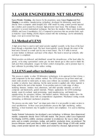
![11
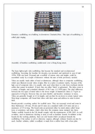
Aeronoutics and space Administrations (NASA), the US Department of Energy, the US
Department of Commerce NIST, the US Department of Defense, Defense Advanced
Research Projects Agency(DARPA), and the Office of Naval Research coordinated studies to
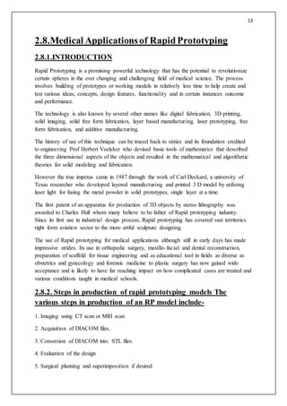
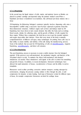
inform strategic planners in their deliberations. One such report was the 1997 Rapid
Prototyping in Europe and Japan Panel Report[2] in which Joseph J. Beaman[8] founder of
DTM Corporation [DTM RapidTool pictured] provides a historical perspective:
“ The roots of rapid prototyping technology can be traced to practices in topography and
photosculpture. Within TOPOGRAPHY Blanther (1892) suggested a layered method
for making a mold for raised relief paper topographical maps .The process involved
cutting the contour lines on a series of plates which were then stacked. Matsubara
(1974) of Mitsubishi proposed a topographical process with a photo-
hardening photopolymer resin to form thin layers stacked to make a casting mold.
PHOTOSCULPTURE was a 19th-century technique to create exact three-dimensional
replicas of objects. Most famously Francois Willeme (1860) placed 24 cameras in a
circular array and simultaneously photographed an object. The silhouette of each
photograph was then used to carve a replica. Morioka (1935, 1944) developed a
hybrid photo sculpture and topographic process using structured light to
photographically create contour lines of an object.The lines could then be developed
into sheets and cut and stacked, or projected onto stock material for carving. The
Munz(1956) Process reproduced a three-dimensional image of an object by selectively
exposing, layer by layer, a photo emulsion on a lowering piston. After fixing, a solid
transparent cylinder contains an image of the object. ”
— Joseph J. Beaman[9]
The technologies referred to as Solid Freeform Fabrication are what we recognize today as
rapid prototyping, 3D printing or additive manufacturing: Swainson (1977), Schwerzel
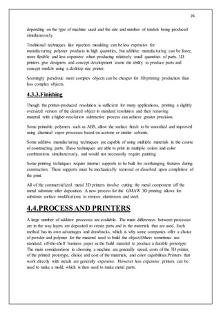
(1984) worked on polymerization of a photosensitive polymer at the intersection of two
computer controlled laser beams. Ciraud (1972)
considered magnetostatic or electrostatic deposition with electron beam, laser or plasma for
sintered surface cladding. These were all proposed but it is unknown if working machines
were built. Hideo Kodama of Nagoya Municipal Industrial Research Institute was the first to
publish an account of a solid model fabricated using a photopolymer rapid prototyping
system (1981).[2] Even at that early date the technology was seen as having a place in
manufacturing practice. A low resolution, low strength output had value in design
verification, mould making, production jigs and other areas. Outputs have steadily advanced
toward higher specification uses.[10]
Innovations are constantly being sought,to improve speed and the ability to cope with mass
production applications.[11] A dramatic development which RP shares with related CNC areas
is the freeware open-sourcing of high level applications which constitute an entire CAD-
CAM toolchain. This has created a community of low res device manufacturers. Hobbyists
have even made forays into more demanding laser-effected device designs.[12]](https://image.slidesharecdn.com/advancemanufacturigtechnique1-copy-171116134611/85/Advance-manufacturig-technique1-copy-11-320.jpg)

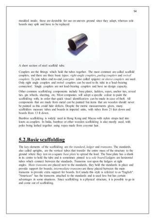
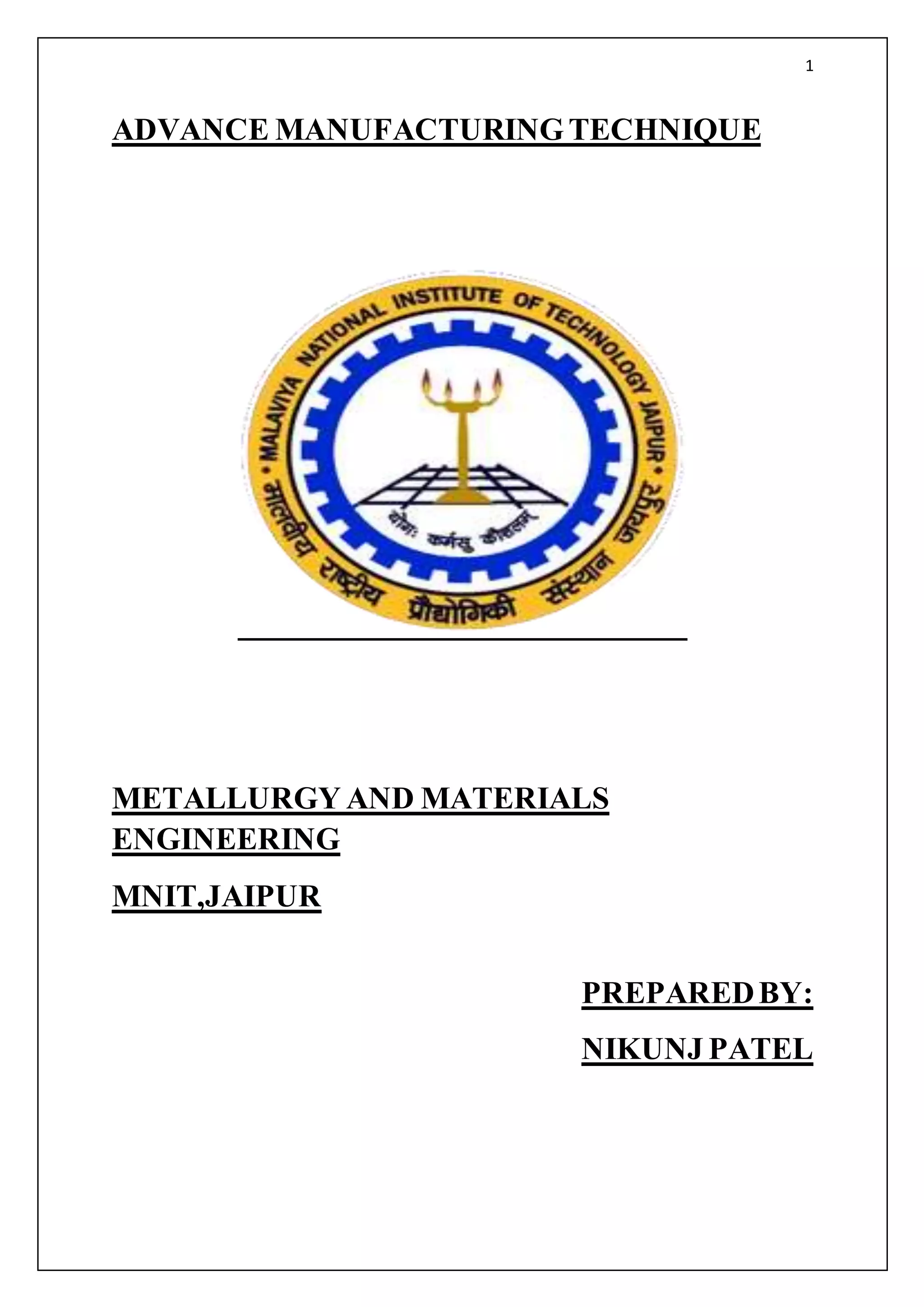
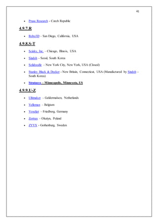
![36
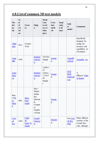
Mo
del
na
me
Ye
ar
of
cre
ati
on
Creat
or
Origi
n
Mode
l size
(verti
ces or
trian
gles)
Crea
tion
meth
od
Inspi
ratio
n (if
any)
Link
to
model
Comments
E.
Torrance
, Donald
P.
Greenber
g, Benne
tt
Battaile
one of them is
considered the
standard
Cornell Box.
See
also History of
the Cornell
Box
Davi
d[8][9]
Stanford
Universi
ty
About
1 billion
polygon
s
Scanne
d[7]
Michel
angelo's
5-meter
statue
of Davi
d
See
comment
Only available
to established
scholars and
for non-
commercial
use only.
Fertil
ity
AIM@S
HAPE
Reposito
ry
241,607
vertices,
483,226
triangle
s
Scanne
d
From the
AIM@S
HAPE
Reposito
ry
Small statue
with two
joined figures.
Laser scanned
from a stone
sculpture.
Happ
y
Budd
ha
1996[
4]
Brian
Curless,
Marc
Levoy[4]
Stanford
Universi
ty
1,087,4
74
triangle
s and
543,524
vertices
Scanne
d
Budaist
atuette[5
]
happy_re
con.tar.g
z
Phleg
matic
Drag
on[6]
2007
See
comment
Eurogra
phics20
07
conferen
ce
original:
667,214
faces;
smoothe
d:
480,076
Scanne
d
See
comment
See also EG
2007
Phlegmatic
Dragon](https://image.slidesharecdn.com/advancemanufacturigtechnique1-copy-171116134611/85/Advance-manufacturig-technique1-copy-36-320.jpg)
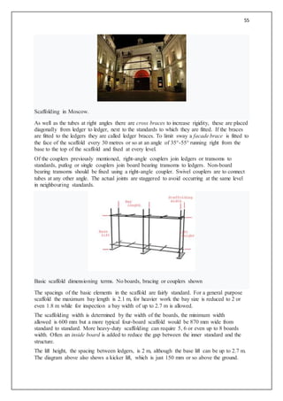
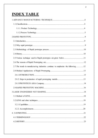
![37
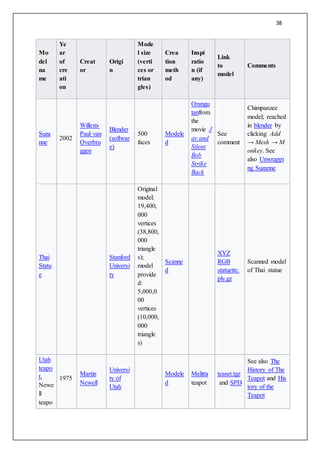
Mo
del
na
me
Ye
ar
of
cre
ati
on
Creat
or
Origi
n
Mode
l size
(verti
ces or
trian
gles)
Crea
tion
meth
od
Inspi
ratio
n (if
any)
Link
to
model
Comments
faces
Spot 2012
Keenan
Crane
The
Californ
ia
Institute
of
Technol
ogy
2,930
vertices,
5,856
triangle
s
Modele
d
From
Keenan's
3D
Model
Reposito
ry
A spotted cow
homeomorphic
to a sphere.
Comes with
Catmull-Clark
control mesh,
quadrangulatio
n,
triangulation,
vector texture,
and bitmap
texture. All
meshes are
manifold,
genus-0
embeddings.
Stanf
ord
Bunn
y
1993-
94
Greg
Turk, M
arc
Levoy
Stanford
Universi
ty
69,451
triangle
s[2]
Scanne
d
Clay bu
nny[3]
bunny.tar
.gz
Stanf
ord
Drag
on
1996
Stanford
Universi
ty
1,132,8
30
triangle
s
Scanne
d
dragon_r
econ.tar.
gz
Chinese
dragon.
Stanf
ord
Lucy
Stanford
Universi
ty
14,027,
872
vertices,
28,055,
742
triangle
s
Scanne
d
lucy.tar.g
z
Scanned model
of Christian
angel.](https://image.slidesharecdn.com/advancemanufacturigtechnique1-copy-171116134611/85/Advance-manufacturig-technique1-copy-37-320.jpg)
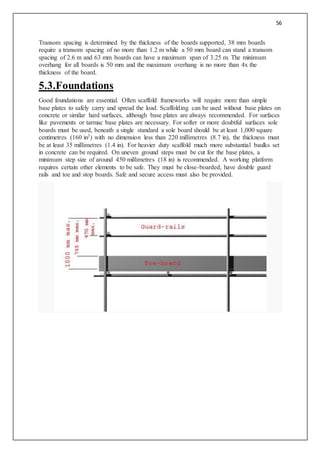
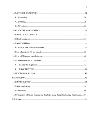
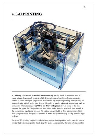
![42
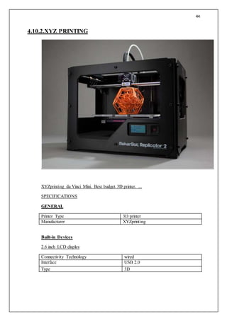
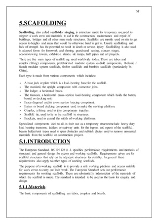
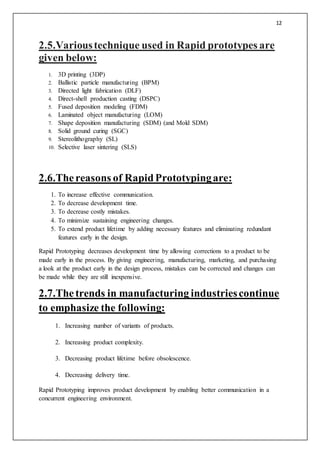
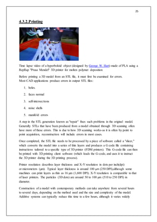
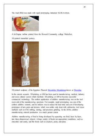
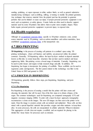
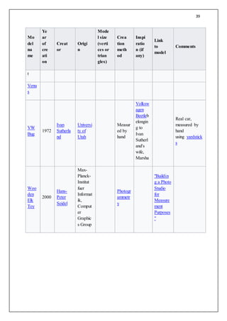
4.10.WORLDBEST 3D PRINTER
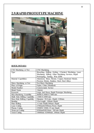
4.10.1.MakerBot Replicator
PrintTechnology FusedDepositionModeling
BuildVolume 28.5L X15.3 W X 15.5 H CM
[11.2 X 6.0 X 6.1 IN]
Layer Resolution 100 Microns[0.0039 IN]
PositioningPrecision XY: 11 Microns [0.0004 IN]
Z: 2.5 Microns [0.001 IN]
FilamentDiameter 1.75MM [0.069 IN]
Nozzle Diameter 0.4MM [0.015 IN]
MECHANICAL SPECIFICATIONS
Chassis PowderCoatedSteel
Body PVCPanels
[9.8 X 6.3 X 5.9 IN]
BuildPlatform Acrylic
XYZ Bearings Wear-resistant,oil-infusedbronze
StepperMotors 1.8o
Stepangle with1/16 micro-
stepping
DIMENSIONS
Productwithoutspool 49 (L) X 32 (W) X 38 (H) CM
[19.1 X 12.8 X 14.7 IN]
Productwithspool 49 (L) X (42 (W) X 38 (H) CM
[19.1 X 16.5 X 14.7 IN]
ShippingDimensions 59 (L) X 55 (W) X 43 (H) CM
[23 X 21.5 X 17 IN]](https://image.slidesharecdn.com/advancemanufacturigtechnique1-copy-171116134611/85/Advance-manufacturig-technique1-copy-42-320.jpg)
![43
ProductWeight 11.5 KG [25.4 LBS]
ShippingWeight 16.8 KG [37.0 LBS]
SOFTWARE
YOUTUBE VIDEO
https://youtu.be/EomLOykZhms
Software Bundle MakerBot MakerWare
File Types STL, OBJ,THING
OperatingSystems Windows(XP32-bit/7+)
MAC OS X (10.6+)
Linux (Ubuntu12.04+)
Connectivity USB, SD Card (Bothincluded)](https://image.slidesharecdn.com/advancemanufacturigtechnique1-copy-171116134611/85/Advance-manufacturig-technique1-copy-43-320.jpg)